
Before you start
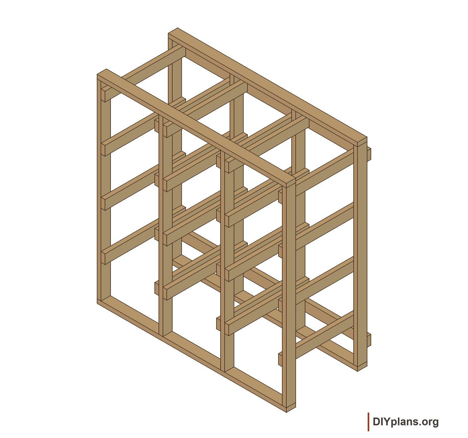
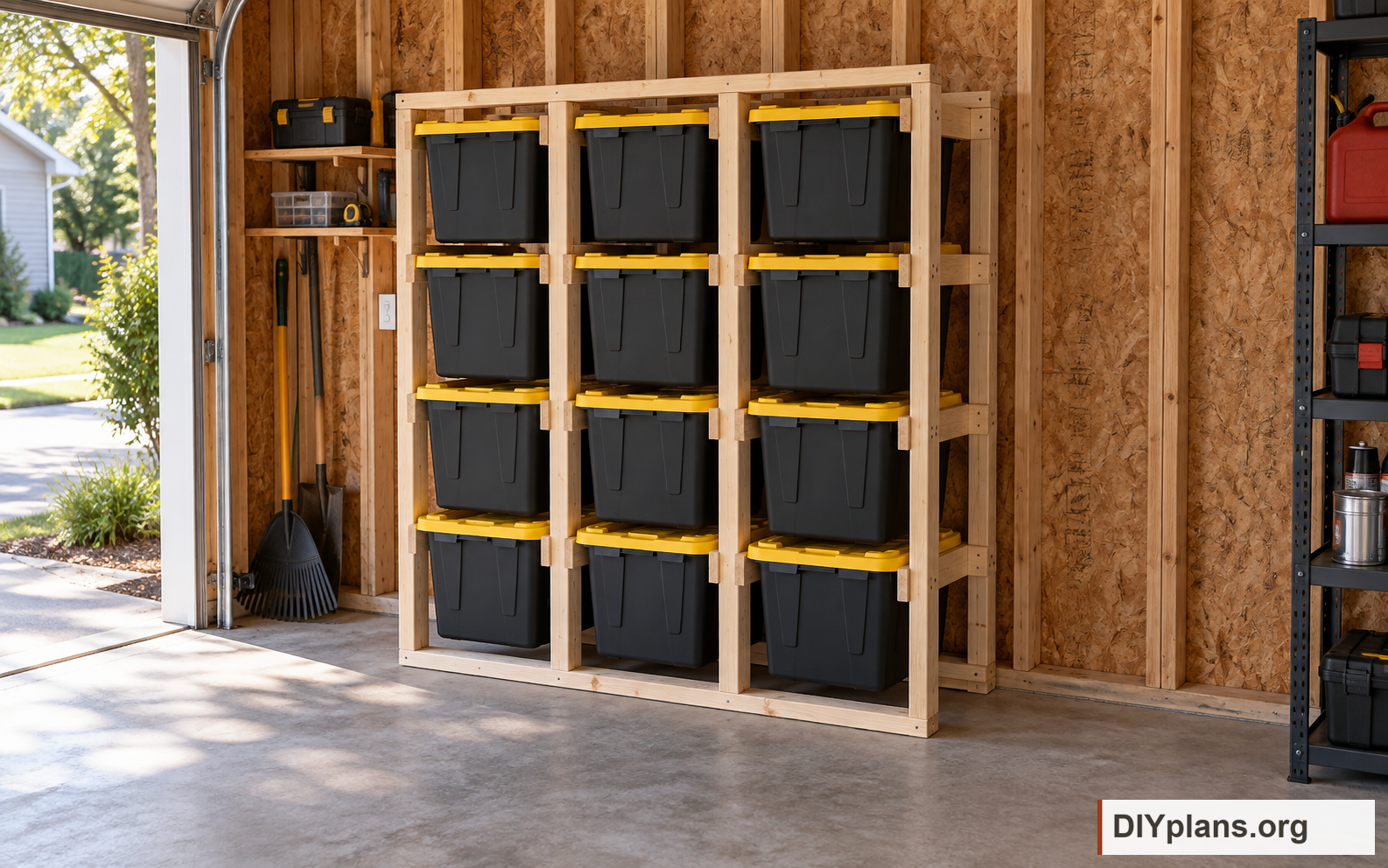
- Use this plan for twelve totes, three wide and four high. Each tote hangs from its molded supporting lip with its bottom clear. The lid, handles and latches must not carry the load.
- Check your actual totes against the supplied exterior envelope of 28 5/8 inches long, 19 5/8 inches wide and 15 3/16 inches high. The supplied interior dimensions of 23 × 14 × 14 5/16 inches do not establish the outside body or supporting-lip fit.
- Fit an actual tote between two runners before cutting the six full-width boards. The 18-1/2-inch runner gap shown in the CAD is a reference, not a confirmed tote measurement. This plan permits a fitted gap from 17 1/8 to 20 inches.
- Choose totes with a sound, continuous molded lip and a flat underside that can bear on both runners. Reject cracked, damaged, flexible or unsuitable lips. Stop if your totes cannot pass the fit checks.
- Buy 22 eight-foot 2x4 boards. Use actual 1-1/2 × 3-1/2-inch stock with sound joint areas. Allow 1/8 inch for each saw cut and 1/4 inch for end trimming. One optional spare covers defects.
- Select wood construction screws and pilot bits for the lumber. Buy 150 screws at 2-1/2 inches and 20 at 4-1/2 inches; 128 and 16 respectively are installed. Follow the screw maker's pilot, spacing and edge-distance requirements. Do not use drywall screws.
- Choose the installation wall before building. Both wall ledgers must attach to sound wall structure and all four rear posts. This rack relies on those connections for sideways restraint and is not freestanding.
- For a timber-stud wall, provide at least three studs per ledger and 12 suitable structural wall screws. A 4-inch screw provides 2 inches of stud embedment through a 1-1/2-inch ledger and 1/2-inch drywall. Select longer screws for thicker finishes or solid spacers. Masonry, metal studs, damaged walls or inaccessible studs need a different suitable attachment detail; drywall-only anchors do not meet this plan.
- Arrange a helper, clamps, temporary braces and support blocks for assembly. Choose a firm, dry floor and leave about 30 inches in front for tote withdrawal, plus room to stand and carry a tote.
- Treat this as an unbuilt design. Neither the rack and wall attachment nor the tote lip has an established load rating. A successful fit check does not establish hanging capacity or long-term resistance to plastic creep.
Dimensions and opening sizes
- Reference overall widthAt fitted runner gap G = 18 1/2 in only. Actual widthW=3G+15.
- 70 1/2 in
- Installed wood depth30-inch runners plus 1 1/2-inch wall ledgers, before spacers.
- 31 1/2 in
- Overall heightIncludes 1 1/2-inch top and bottom plates.
- 74 in
- Vertical row spacingRunner-top to runner-top.
- 17 1/2 in
- Reference clear runner gapUnmeasured tote-lip fit. Use the mandatory jig and width formula.
- 18 1/2 in
Shopping list
| Buy | Material | Stock size |
|---|---|---|
| 22 boards | 2x4 lumber | 8 ft, actual 1-1/2 x 3-1/2 in |
| 150 | Wood construction screws | 2-1/2 in |
| 20 | Wood construction screws | 4-1/2 in |
| 12 | Structural wood screws for timber studs | 4 in minimum for 1/2 in drywall |
| 12 | 27 gallon totes with suitable molded supporting lips | Up to 28 5/8 L x 19 5/8 W x 15 3/16 H in |
Quantity notes
22 eight-foot 2x4 boards at the reference width or any fitted gapG from 17 1/8 to 20 inches. All wood is actual 1 1/2 x 3 1/2 inches. Allow 1/8 inch saw kerf and 1/4 inch end trimming. Screws and wall attachment are separate from lumber.
- 2x4 lumber, 8 ft, actual 1-1/2 x 3-1/2 in: 8 posts, 24 runners, 4 plates, 2 wall ledgers. Cut six width pieces only after fitting the runner gap. One optional spare covers defects.
- Wood construction screws, 2-1/2 in: 96 runner screws and 32 plate screws, 128 installed. No drywall screws.
- Wood construction screws, 4-1/2 in: 16 installed through 3 1/2 inch rear posts into 1 1/2 inch wall ledgers, 1 inch embedment.
- Structural wood screws for timber studs, 4 in minimum for 1/2 in drywall: Two per stud at a minimum of three studs per ledger. Two ledgers required. At least 2 inches into sound studs; actual wall and screw requirements govern.
- 27 gallon totes with suitable molded supporting lips, Up to 28 5/8 L x 19 5/8 W x 15 3/16 H in: Confirm supporting lip, body and lid fit using the jig before cutting width pieces.
Required installation supplies
- Select wood construction screws and pilots for the actual dry lumber. Follow manufacturer spacing and edge-distance requirements.
- Select wall attachment for the actual wall. Both upper and lower ledger attachments are required. Masonry or metal studs need a suitable different fixing system.
Optional material depending on installation
- One spare 2x4 x 8 for defects.
- Floor shims cut from 2x4 offcuts, as needed for all eight posts.
Tools & equipment
- Tape measure, pencil and square
- Clamps and temporary assembly supports
- Circular saw with guide or miter saw
- Drill/driver and suitable pilot bits
- Level and stud finder
- Eye/hearing protection and sanding block
BEFORE YOU BUILD
Use this work at your own risk
No person or organization makes any guarantee or warranty, express or implied, regarding this design, its documentation, digital files, or website views. They are not professional services and do not create an architect-client or other professional-client relationship. No promise is made about accuracy, completeness, reliability, code compliance, or fitness for your project.
Buildings and building projects are complex, and many things can go wrong. You are responsible for checking dimensions and site conditions, choosing suitable materials and methods, obtaining permits, following codes and manufacturer instructions, and getting qualified professional help when needed. To the fullest extent permitted by law, DIYPlans.org disclaims liability for damages resulting from use of this work. Read the FAQ about your responsibilities.
CC CC BY-NC-SA 4.0 InternationalShare and adapt this free design for noncommercial purposes with appropriate credit. Link to the license, indicate changes, and license adaptations under the same terms.
Instructions

01 Cut the posts and runners
- Cut eight posts to 71 inches, one from each of eight boards. Keep every post the same length and cut the ends square.
- Cut 24 runners to 30 inches, three from each of eight more boards. Reserve the remaining six boards for the fitted-width cuts.
- Sand the runner tops smooth and ease sharp edges without reducing the flat bearing surface. Reject split or knot-damaged joint areas.
Check: Count eight 71-inch posts and twenty-four 30-inch runners. Leave all six width boards uncut.

02 Measure the supporting lip
- Turn an empty tote over and find the flat underside of its molded supporting lip. Exclude the lid, handles and latches from the bearing measurement.
- Measure B, the widest outside body width throughout the 3-1/2-inch-tall zone below the lip. Include ribs and shoulders along the full length that will pass between the runners.
- Measure L across the supporting lip and inspect its underside for continuous flat bearing on both sides.
- Close the lid and measure from the lip-bearing plane to the highest lid point. Require no more than 1-1/2 inches.
Check: Record B, L and the height above the supporting lip for the largest closed tote.
03 Fit two test runners
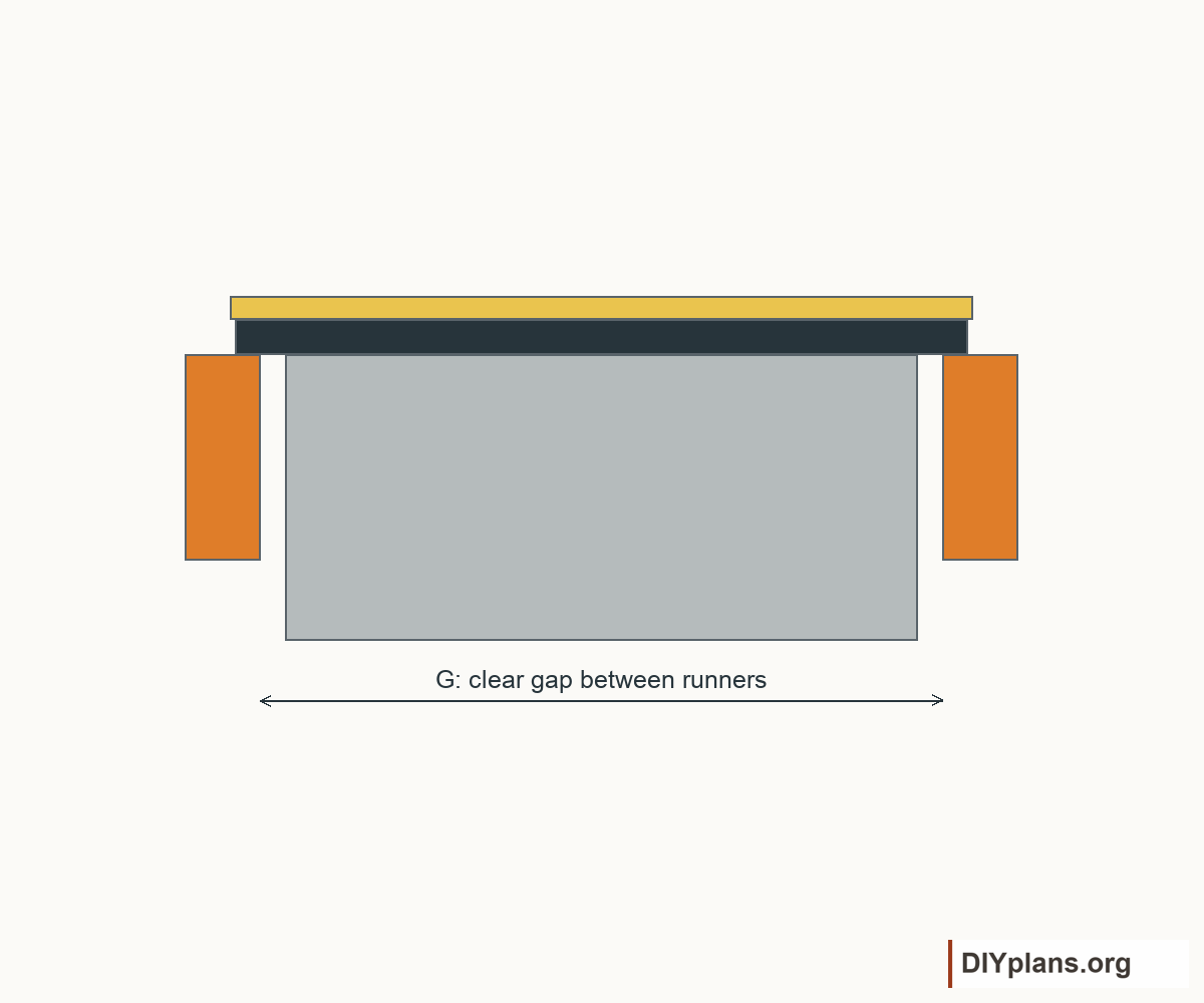
- Clamp two of the 30-inch runners parallel on secure temporary supports. Stand them on edge with their 1-1/2-inch-wide tops supporting the tote lip.
- Start the clear gap G between the runners at B plus 1/4 inch. Slide in the largest closed tote and adjust the gap until it moves without binding.
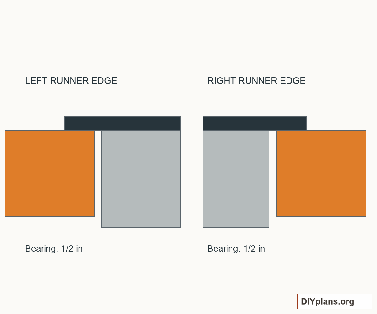
- Keep at least 1/8 inch of body clearance on each side when centered, and at least 3/8 inch of flat lip bearing on each runner. Do not count rounded wood edges as bearing.
- Keep G between 17 1/8 and 20 inches. Check that the future clear post opening, G plus 3 inches, leaves at least 1/4 inch on each side of the 19 5/8-inch lid envelope.
Check: The tote hangs by its molded lip, slides freely and leaves its bottom unsupported.
Play movementStop movement
04 Check the tote's side play

- Push the tote fully left, then fully right within its natural play. Repeat throughout insertion, checking that both runners retain at least 3/8 inch of flat lip bearing at both extremes.
- For symmetric lips, check that L + B − 2G is at least 3/4 inch. Confirm the actual flat contact as well; overall width alone cannot prove bearing.
- Adjust G and repeat the sliding and side-play checks if needed. Test the other totes for variations before accepting one gap for all twelve positions.
- Record the accepted G, B and L, the bearing at both extremes, and the lid clearance and height. Use this fitted G for every width cut.
Check: Every tote passes both clearance and bearing checks. Stop if any tote cannot pass within the permitted gap range.
05 Cut the six width boards
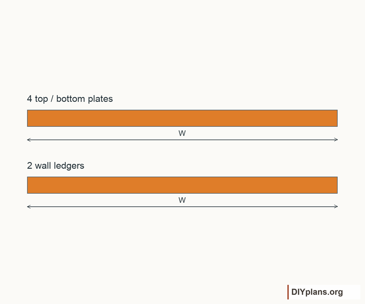
- Calculate the rack width W as 3 × your fitted G + 15 inches. For example, G of 18-1/2 inches gives W of 70-1/2 inches; use that length only if your tote passed at that gap.
- Cut four plates and two wall ledgers to W, using one of the six reserved boards for each piece. Keep all six lengths identical and the ends square.
- Label two bottom plates, two top plates and two wall ledgers. Label four front posts, four rear posts and the left and right runners for each bay, viewed from the front.
Check: Count 38 wood pieces: eight posts, 24 runners, four plates and two ledgers.
06 Mark the runner tops
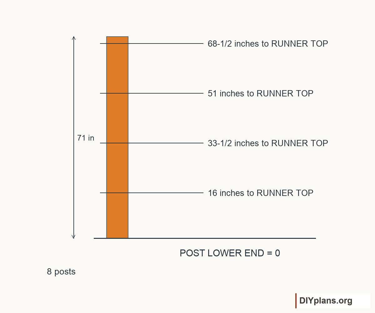
- Orient each post with 1-1/2 inches across the rack width and 3-1/2 inches front to back. Identify its lower end before marking.
- Measure from each post's lower end and mark runner tops at 16, 33-1/2, 51 and 68-1/2 inches.
- Transfer matching lines onto both runner faces of the four middle posts. Mark only the inward runner face of each outer post.
Check: All eight posts have matching marks. On the bottom plates, these runner tops will stand 17-1/2, 35, 52-1/2 and 70 inches above the rack bottom.

07 Mark the runner screw holes
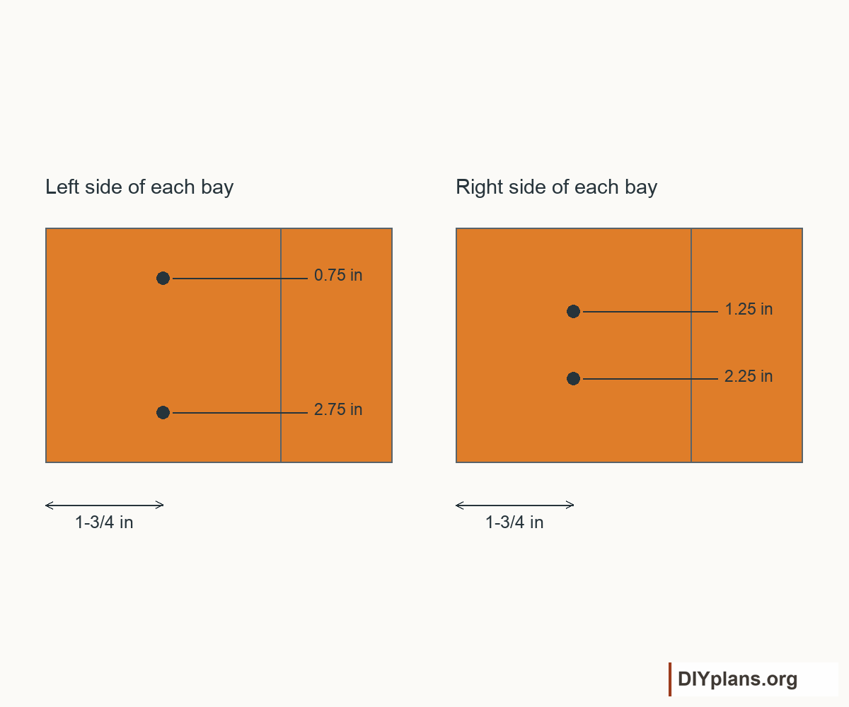
- Mark a screw line 1-3/4 inches inward from each end of every runner.
- On each bay's left runner, mark screws 3/4 and 2-3/4 inches below the top. On its right runner, mark them 1-1/4 and 2-1/4 inches below the top.
- Keep these left and right patterns distinct. They stagger screws entering shared middle posts from opposite sides.
- Predrill as required by the selected screw maker and to prevent splitting.
Check: Each runner has two screw positions at each end, with different heights for left and right runners.
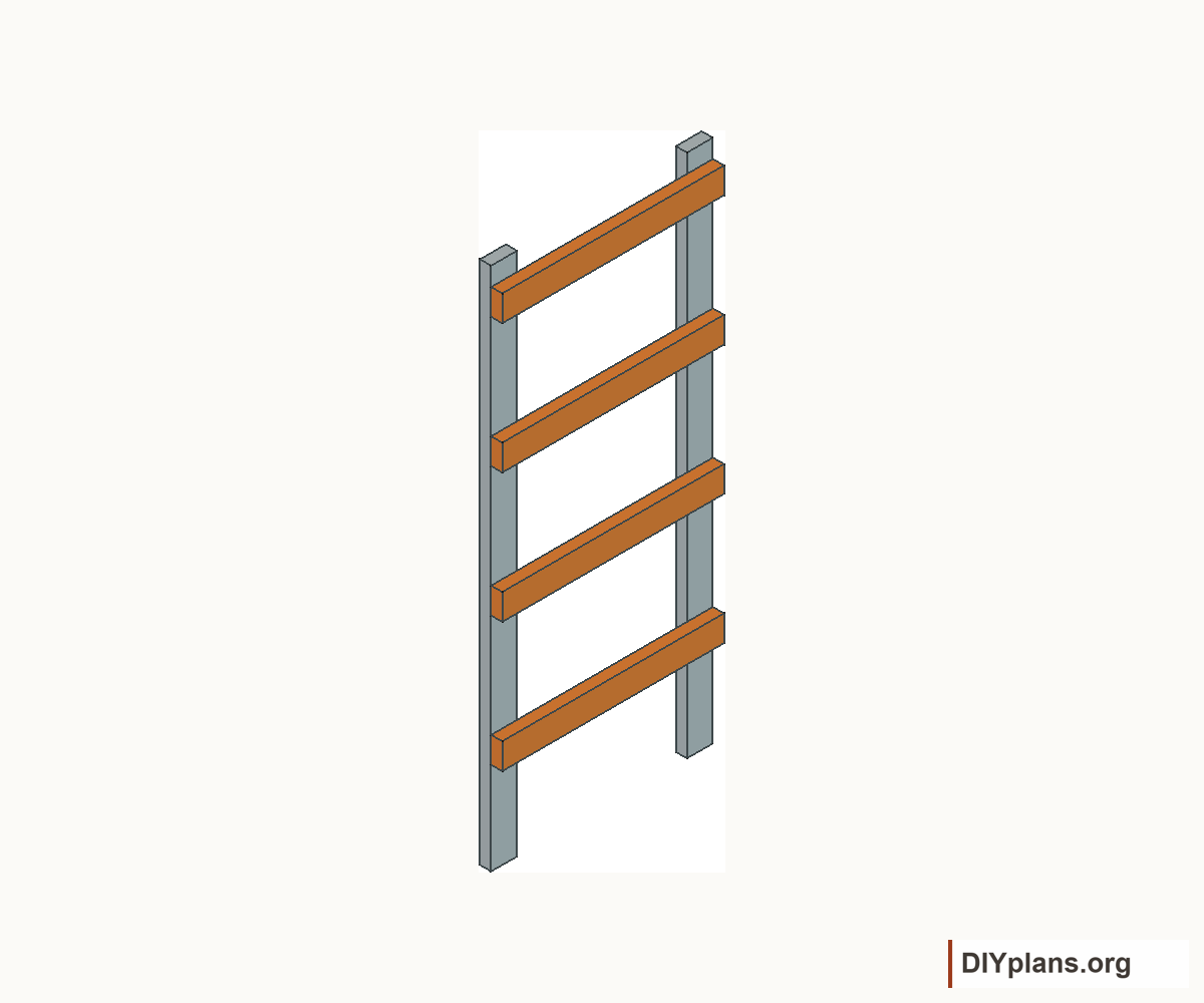
08 Build the outer frames
- Lay one front post and one rear post parallel on a flat surface. Set their outside front-to-back distance to 30 inches and their inside distance to 23 inches.
- Clamp four runners to the inward side, with their tops on the marks and ends flush with the outside front and rear post edges. Keep each runner 3-1/2 inches tall.
- Compare the frame diagonals, then drive two 2-1/2-inch construction screws through each runner end into the post. Seat the heads without crushing the wood.
- Build the opposite outer frame as a mirror image, with four inward-facing runners. Add temporary bracing before handling either frame.
Check: Both outer frames are square and 30 inches deep. Their eight runners use 32 screws.
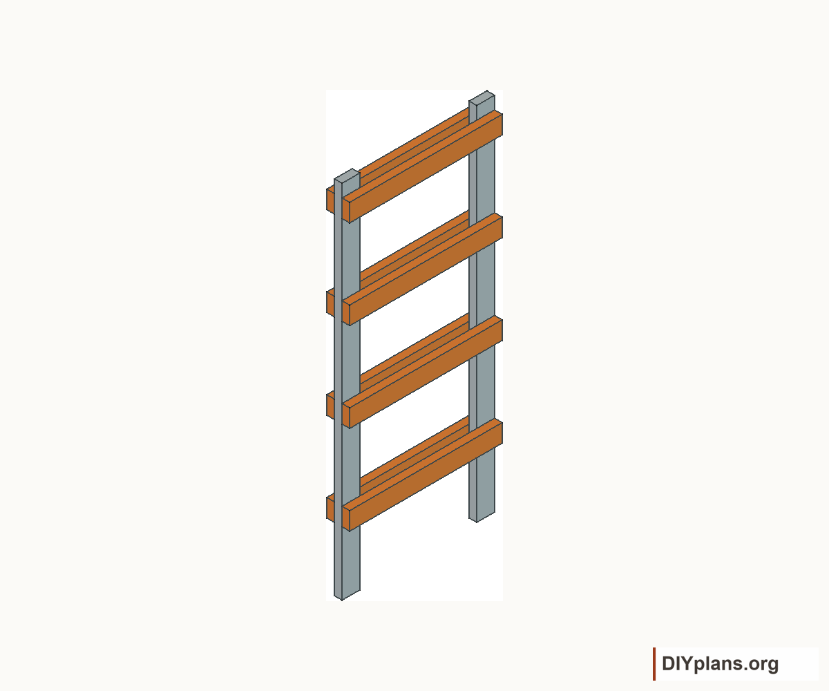
09 Build the middle frames
- Lay out each remaining post pair at the same 30-inch outside depth. Clamp four runners to each side with their tops on the marks and their ends flush with the posts.
- Use each bay's left or right screw pattern on the correct face. Fasten every runner end with two 2-1/2-inch construction screws, keeping opposite-face screws staggered.
- Compare diagonals before final tightening and check that all screw tips remain in the receiving posts. Brace both middle frames for handling.
Check: Each middle frame has eight runners. All four frames together have 24 runners and 96 screws across 48 runner-end joints.
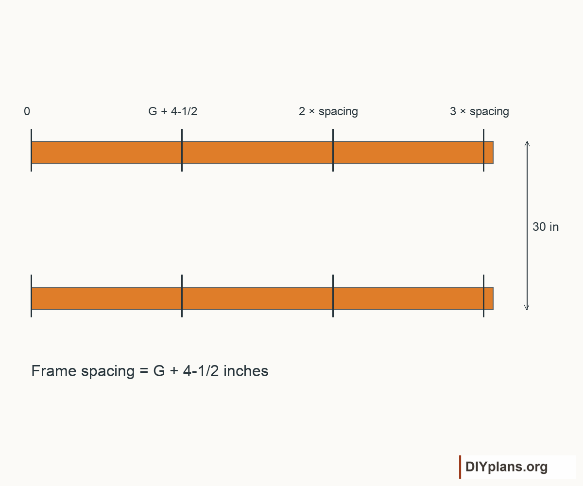
10 Lay out the bottom plates
- Lay the two bottom plates flat, one for the front posts and one for the rear posts. Keep their outer front and rear edges 30 inches apart.
- Measure from the same left end on both plates. Mark the post left edges at 0, G + 4-1/2, 2 × that spacing and 3 × that spacing. At reference G of 18-1/2 inches, these marks are 0, 23, 46 and 69 inches.
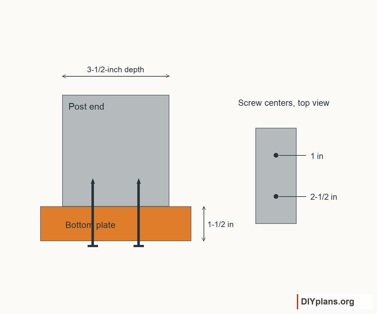
- Mark each 1-1/2-inch-wide post footprint. Center its two screws across that width and place them 1 and 2-1/2 inches from the plate's front edge.
Check: Matching front and rear marks give three clear post openings of G + 3 inches. Each plate lies 1-1/2 inches thick and 3-1/2 inches front to back.
Play movementStop movement

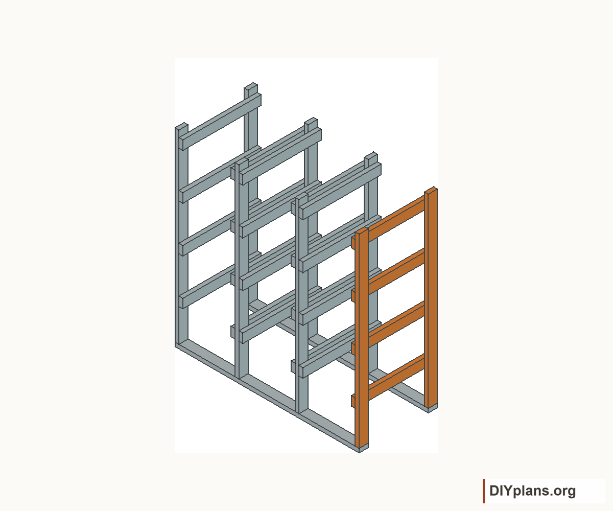
11 Attach the four frames
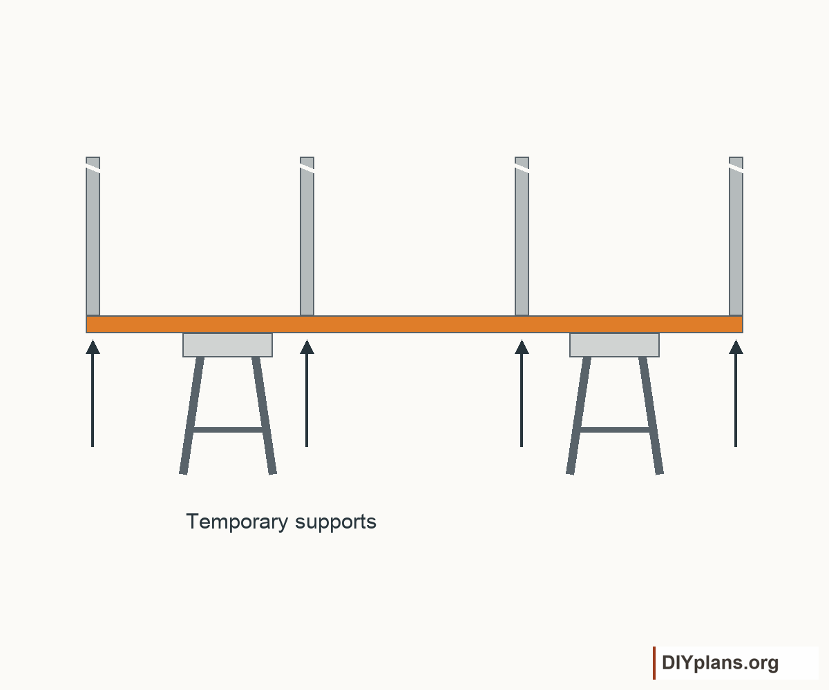
- Set secure temporary blocks beneath the plates to provide driver access underneath. Keep both plates level and supported while attaching the frames.
- With a helper, position the four braced side frames on their matching bottom-plate marks. Face the outer-frame runners inward.
- Clamp each post in place and fasten upward through the plate into its end with two 2-1/2-inch construction screws. Keep the assembly securely supported while working underneath.
- Check the runner gap at the front, middle and rear of each pair. Adjust the frame positions before tightening if any gap differs from fitted G.
- Keep temporary bracing in place and support the rack on its bottom plates after removing the access blocks.
Check: All eight post ends are fastened with 16 bottom-plate screws. The frames stand plumb with matching runner gaps.
12 Attach the top plates
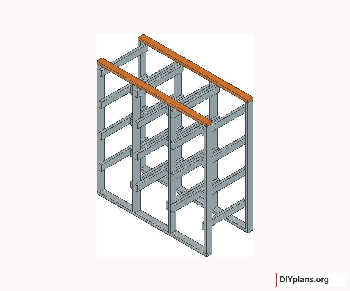
- Place the front and rear top plates flat on the post ends. Keep them flush with the rack width and outside front and rear edges.
- Fasten each post with two 2-1/2-inch construction screws through the plate. Center across the post width and place screws 1 and 2-1/2 inches front to back, as on the bottom plates.
- Check all twelve runner gaps for fitted G at the front, middle and rear. Correct taper or twist before final tightening, and compare the rack diagonals.
Check: The rack is square, 74 inches high and 30 inches deep. The top and bottom plates use 32 screws total; temporary bracing remains in place.
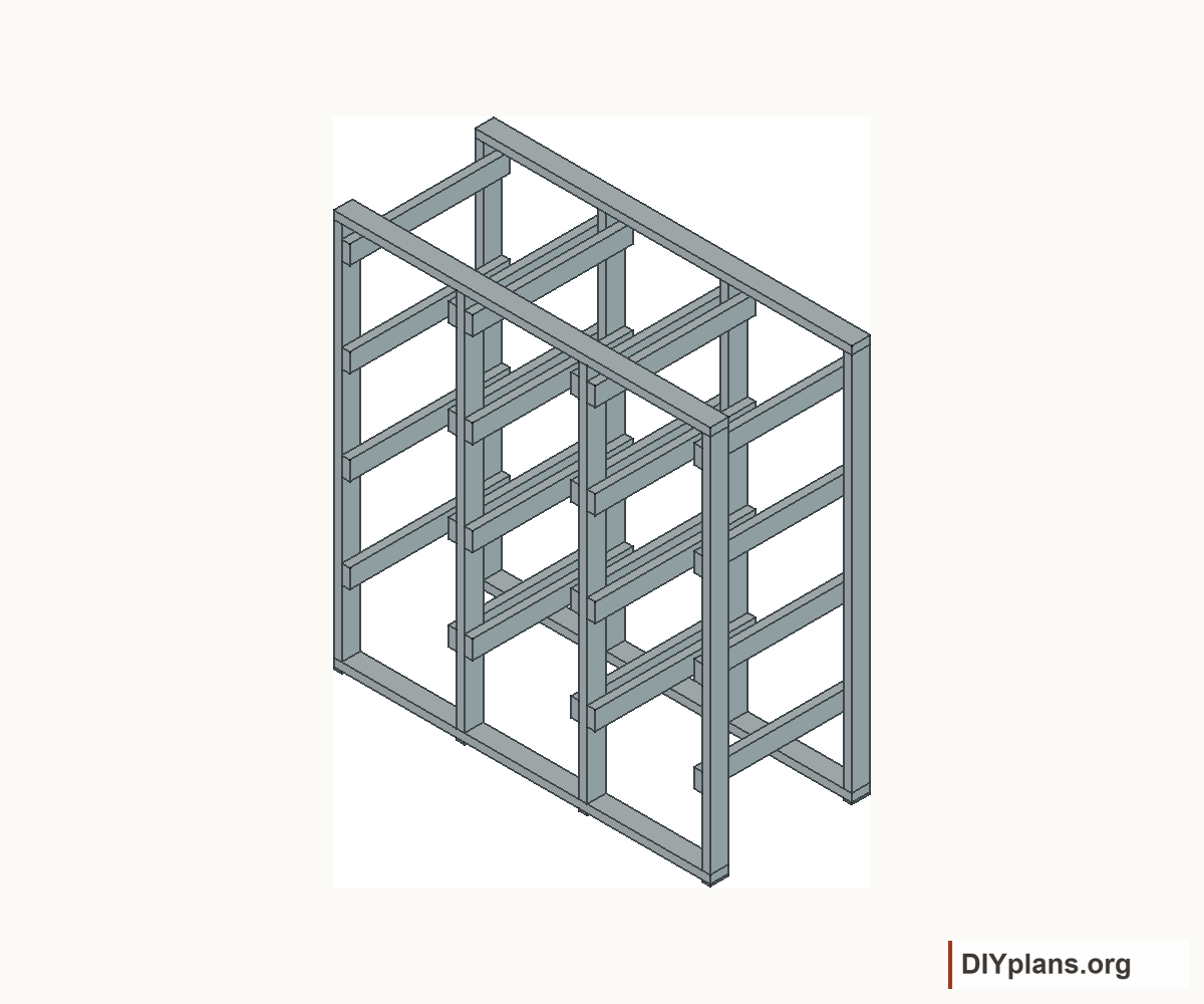
13 Level the empty rack
- Move the empty, temporarily braced rack to its installation position with a helper. Set it on the firm, dry floor selected earlier.
- Shim beneath the bottom plates with 2x4 offcuts where needed. Support all eight post positions firmly and check the rack for level and plumb.
- Transfer the level bottom of the rack to the wall as a reference line. Measure both wall-ledger heights from this same line, not from an uneven floor.
Check: Every post position bears firmly through a bottom plate. The rack is level, plumb and still temporarily braced.
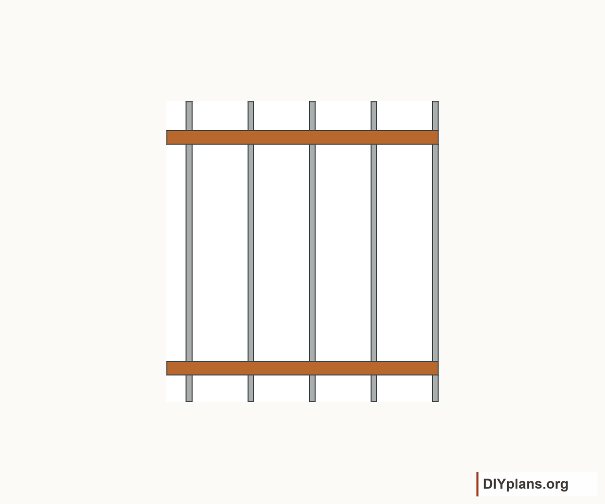
14 Secure the wall ledgers
- Move the empty, temporarily braced rack aside. Locate at least three sound timber studs behind each ledger position and check for wiring and pipes before drilling.
- Set the lower ledger edge 6 inches above the rack-bottom reference line and the upper ledger edge 66 inches above it. Keep both ledgers level, with their 3-1/2-inch faces vertical and flat against the wall.
- Drive two suitable structural wood screws into each stud through each ledger, 12 screws minimum. Follow the selected screw maker's pilot, spacing and edge-distance requirements and provide at least 2 inches of embedment in sound studs.
- Keep wall screws clear of the upcoming rear-post screw paths. If a position conflicts, move the wall screw within its stud and permitted edge distances while retaining both required screws per stud.
Check: Both ledgers are secured to at least three sound studs each at the marked heights. Use the suitable alternative fixing detail selected earlier for other wall types.
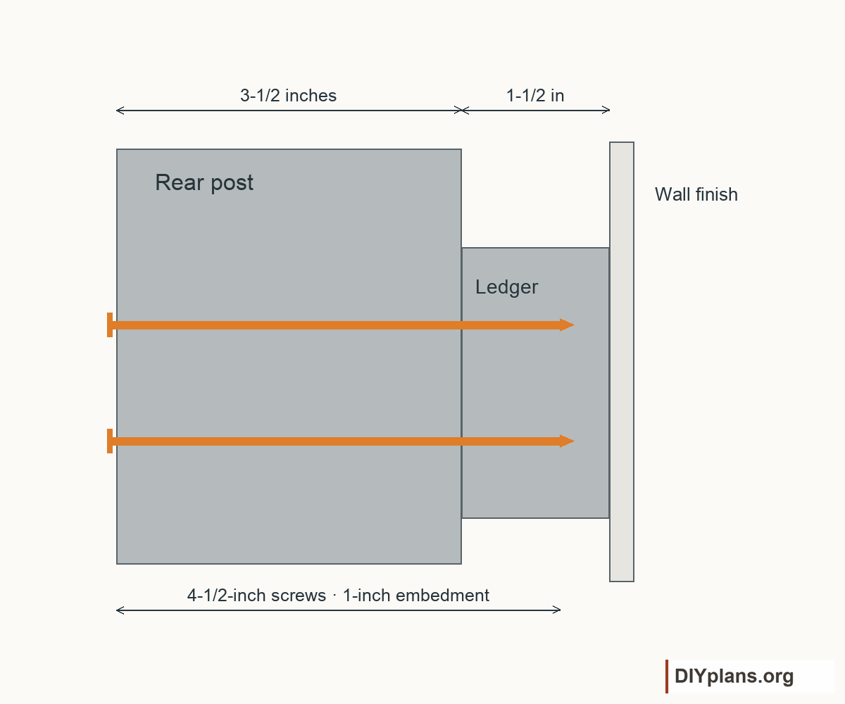
15 Attach the rack to both ledgers
- Move the empty rack back with a helper and restore its shims, level and plumb. Bring all four rear posts into firm contact with both ledgers.
- Mark the center of each rear post's 1-1/2-inch width. Measure from the level rack-bottom reference and mark screws at 7 and 8-1/2 inches for the lower ledger, and 67 and 68-1/2 inches for the upper.
- Drive two 4-1/2-inch construction screws through each rear post into each ledger from inside the rack. The screws pass through 3-1/2 inches of post and penetrate 1 inch into the ledger; use 16 screws total.
- Remove temporary bracing only after both ledgers and every rear-post connection are complete. Check the empty rack for rocking and sideways movement.
Check: Both ledgers connect all four rear posts to the wall. Installed wood depth is 31-1/2 inches, plus any solid wall spacers.
Play movementStop movement

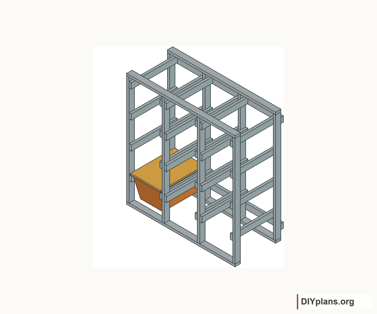
16 Test all twelve positions
- Slide an empty tote into every position. Check that the molded lip bears on both runners while the body, handles and bottom remain clear.
- Repeat the full left and right side-play checks throughout insertion. Keep at least 3/8 inch of flat lip bearing on both runners at both extremes.
- Check that each bottom clears the tote below and both bottom plates. The 17-1/2-inch row spacing gives 2 5/16 inches between equivalent 15 3/16-inch-high totes.
- Check for at least 1 inch between the top-row closed lid and the top-plate underside, which is 72-1/2 inches above the rack bottom.
- Mark a normal seated position so each 28 5/8-inch tote stays supported along the 30-inch runners. Account for the absence of front travel stops when pulling out a tote.
Check: All twelve positions pass the lip-bearing, sliding and vertical-clearance checks without deformation.
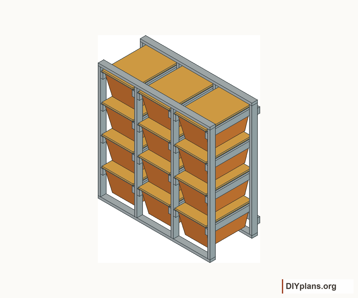
17 Load and inspect the rack
- Use light household contents and place heavier totes in the lower rows. Keep within any tote-maker limits; this plan establishes no hanging-load rating, rim strength, creep life or rack capacity.
- Remove one tote at a time with both hands supporting its weight as it slides out. Never leave a loaded tote partly withdrawn, climb on the rack or hang from a runner.
- Inspect the lips for sagging, whitening and cracking. Check the wood, screws and wall connections for splits, loosening or movement.
- Stop using any affected position if damage, deformation or movement appears. Remember that this design is unbuilt and a successful fit test does not certify its load capacity.
Check: The totes hang by sound molded lips, and the frame and both wall connections show no visible damage or movement.
Sources
Original DIYplans.org plan. Tote illustrations are schematic; no tote-maker endorsement is claimed.