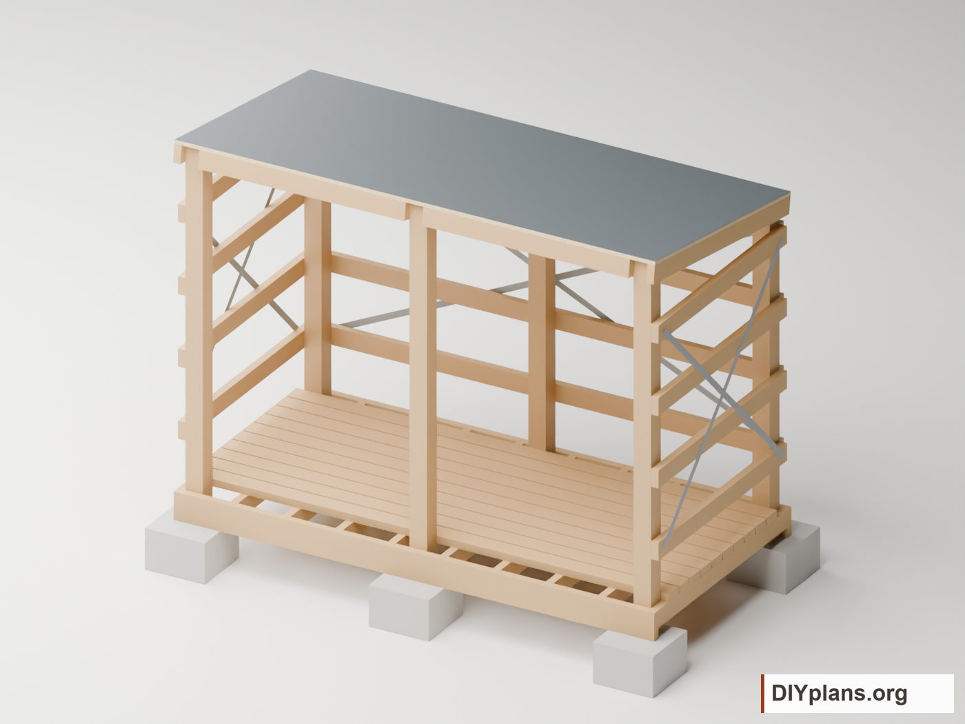
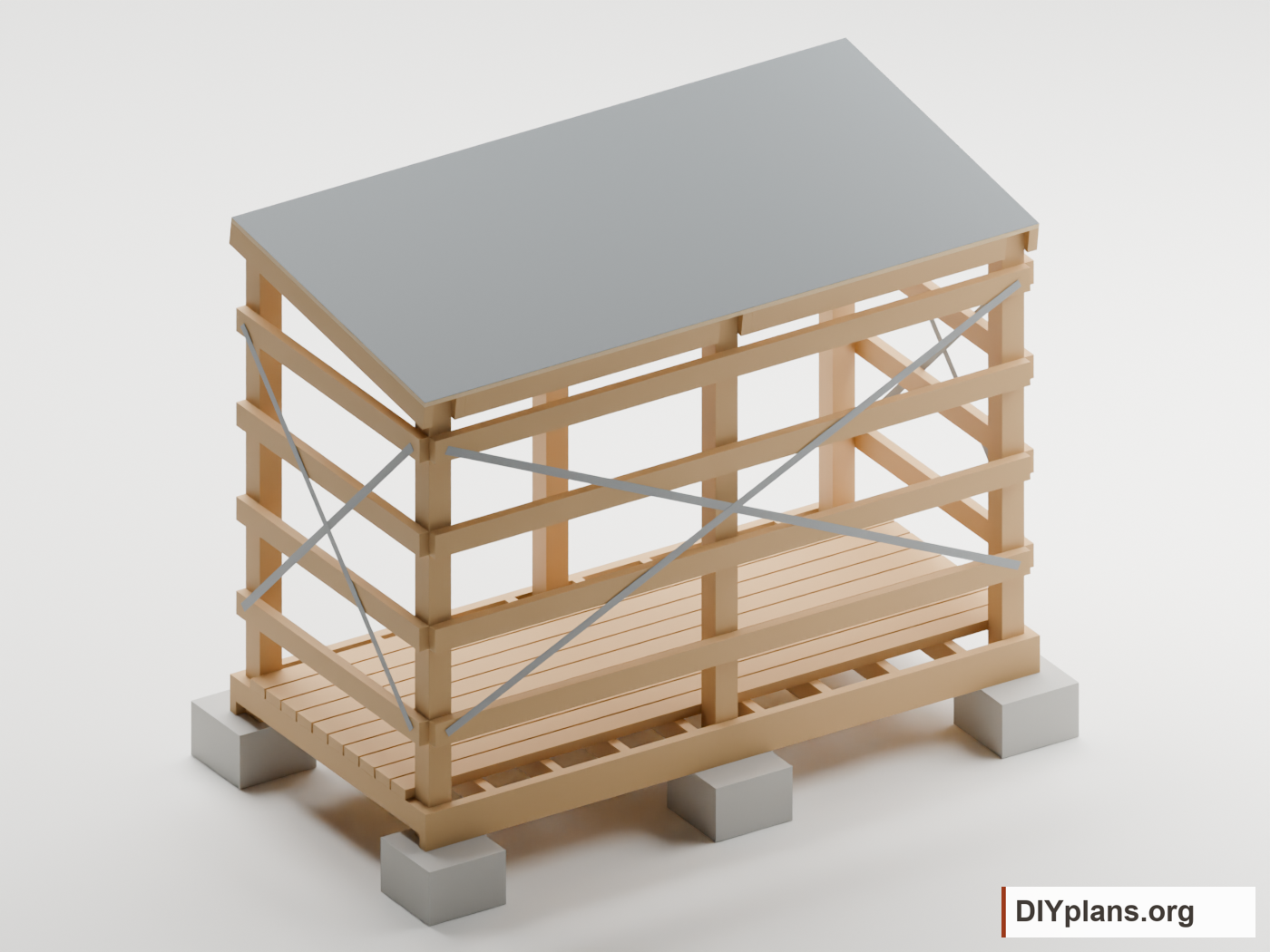

Before you start
- Select the ground anchors and rated diagonal-bracing kits for the site before construction. Deck blocks do not resist uplift.
- Confirm local wind, snow, soil and firewood loads. No structural load rating or physical build test is claimed.
- Choose the specified plywood grade and a complete plywood-compatible low-slope membrane system before buying roof materials.
- Use corrosion-compatible connectors and fasteners for the selected treated lumber. Fastener substitutions need the connector manufacturer approval.
- Use a helper for posts and the roof sheet. Do not stand on the roof.
Dimensions and opening sizes
- Frame widthEight feet, excluding projecting support blocks.
- 96 in
- Frame depthFour feet; the 48 in sloping roof projects 47 1/2 in horizontally.
- 48 in
- Boarded floor depthClear space between the front and rear post rows.
- 38 in
- Roof height above beam bearingAdd actual support height above grade. About 81 7/16 in with the modeled 8 in supports.
- 73 7/16 in
- Floor above beam bearingAdd the support height above grade.
- 7 in
Shopping list
| Buy | Material | Stock size |
|---|---|---|
| 2 boards | Ground-contact treated 2x6 | 10 ft; actual 1-1/2 x 5-1/2 in |
| 3 boards | Ground-contact treated 4x4 | 12 ft; actual 3-1/2 x 3-1/2 in |
| 13 boards | Treated 2x4 | 10 ft; actual 1-1/2 x 3-1/2 in |
| 15 boards | Treated 2x4 | 8 ft; actual 1-1/2 x 3-1/2 in |
| 1 sheet | Exterior-bond plywood roof sheathing | 23/32 Performance Category, 48/24 roof span rating, 4 x 8 ft |
| 6 | Solid concrete deck supports | 12 x 12 in nominal bearing footprint |
| 16 | Corrosion-resistant 2x4 joist hangers | Face mount, approved for single 2x6 header |
| 12 sets | Hot-dip galvanized through-bolts | 3/8 x 6 in with two washers and nut |
| 350 | Exterior structural wood screws | No. 10 x 3 in minimum, corrosion compatible with treated lumber |
| 100 | Exterior wood roof screws | 1-3/4 in minimum, approved for plywood attachment |
| 1 kit | Single-piece EPDM low-slope roof system | At least 5 x 9 ft, nominal 60 mil |
| 3 kits | Rated opposing tension-strap bracing | Rear 89-1/2 x 42 in; two sides 41-1/2 x 42 in |
| 6 assemblies | Ground anchorage matched to the site | One connection at every post |
| 1 container | Cut-end treatment | Compatible with the selected treated wood |
Quantity notes
One shed. Cut allocation includes 1/8 in kerf and uses longer stock for exact 96 in pieces and paired 48 in rafters. Hardware allowances do not replace the selected connector installation schedule.
- Ground-contact treated 2x6, 10 ft; actual 1-1/2 x 5-1/2 in: Cut two 96 in floor beams.
- Ground-contact treated 4x4, 12 ft; actual 3-1/2 x 3-1/2 in: Each yields one 72 in front post and one 66 in rear post.
- Treated 2x4, 10 ft; actual 1-1/2 x 3-1/2 in: Ten 96 in floorboards; three boards each yield two 48 in rafters.
- Treated 2x4, 8 ft; actual 1-1/2 x 3-1/2 in: Four 93 in rear slats; ten 45 in crosspieces; eight 45 in side slats; four 38-1/4 in roof blocks.
- Exterior-bond plywood roof sheathing, 23/32 Performance Category, 48/24 roof span rating, 4 x 8 ft: Strength axis runs along the 96 in width, perpendicular to rafters. Confirm grade and span for local roof loads.
- Solid concrete deck supports, 12 x 12 in nominal bearing footprint: Reference CAD uses 8 in height. Select a level bearing surface that directly supports the beam and adjacent post; actual block height changes overall height.
- Corrosion-resistant 2x4 joist hangers, Face mount, approved for single 2x6 header: Two for each of eight interior crosspieces. Include the exact manufacturer-specified connector nails or screws.
- Hot-dip galvanized through-bolts, 3/8 x 6 in with two washers and nut: Two bolts at each post; check actual stack and thread engagement. Match preservative compatibility.
- Exterior structural wood screws, No. 10 x 3 in minimum, corrosion compatible with treated lumber: 200 floor, 56 wall slat, 24 rafter, 16 roof blocking, 8 assembly and 8 end-crosspiece/post screws; 312 installed, spare allowance included. Hanger and bracing fasteners are separate.
- Exterior wood roof screws, 1-3/4 in minimum, approved for plywood attachment: Fasten deck at 6 in maximum spacing along all six rafters and four edge blocks, unless selected roof/load requirements need closer spacing.
- Single-piece EPDM low-slope roof system, At least 5 x 9 ft, nominal 60 mil: Include plywood-compatible adhesive, edge metal, termination tape, corners and fasteners for a 24 ft perimeter. Follow one manufacturer system.
- Rated opposing tension-strap bracing, Rear 89-1/2 x 42 in; two sides 41-1/2 x 42 in: Anchor into posts through the 1-1/2 in wall slat layer. Manufacturer specifies strap, end anchorage and connector fasteners. Do not use plumbing tape.
- Ground anchorage matched to the site, One connection at every post: Select anchor capacity, embedment and post connectors for soil, wind and local rules before building. Deck blocks provide bearing only.
- Cut-end treatment, Compatible with the selected treated wood: Treat all cuts and holes as the lumber supplier directs.
Required installation supplies
- Ground anchors and post connections sized for the actual site, one at every post.
- Three rated X-bracing systems with post embedment through 1-1/2 in slats.
- Roof sheathing grade and complete EPDM system suited to the site loads and 1.73:12 slope.
- Connector fasteners approved for treated lumber and single-thickness headers.
Optional material depending on installation
- Buy spare lumber for defects; spare stock is not included in the cutting allocation.
Tools & equipment
- Tape measure, pencil, framing square and chalk line
- Circular or miter saw and stable sawhorses
- Drill/driver, pilot bits and through-bolt clearance bit
- Socket wrench and spanners for 3/8 in bolts
- Level, clamps and temporary diagonal braces
- Stable ladders or work platforms
- Roof-system roller, cutters and adhesive tools
- Eye and hearing protection; dust collection
BEFORE YOU BUILD
Use this work at your own risk
No person or organization makes any guarantee or warranty, express or implied, regarding this design, its documentation, digital files, or website views. They are not professional services and do not create an architect-client or other professional-client relationship. No promise is made about accuracy, completeness, reliability, code compliance, or fitness for your project.
Buildings and building projects are complex, and many things can go wrong. You are responsible for checking dimensions and site conditions, choosing suitable materials and methods, obtaining permits, following codes and manufacturer instructions, and getting qualified professional help when needed. To the fullest extent permitted by law, DIYPlans.org disclaims liability for damages resulting from use of this work. Read the FAQ about your responsibilities.
CC CC BY-NC-SA 4.0 InternationalShare and adapt this free design for noncommercial purposes with appropriate credit. Link to the license, indicate changes, and license adaptations under the same terms.
Instructions


01 Prepare six support points
- Choose a firm, draining site with access at the open front and room for air to circulate. Confirm local setbacks, permits and ground-anchor requirements before buying materials.
- Mark an 8 x 4 ft frame rectangle. Match both diagonals at about 107-5/16 in. Mark support centers 3-1/4, 48 and 92-3/4 in from the left end, on lines 3/4 and 47-1/4 in behind the front edge.
- Set six concrete supports on compacted, level bases. Both 96 in floor beams must bear directly on the supports at all three positions. The adjacent posts also need full bearing; choose supports that accommodate both.
- Use the actual block geometry to check bearing before proceeding. The model shows solid 12 x 12 x 8 in reference supports; these are not a specification for a particular precast product. Their reference footprint extends to 101-1/2 x 58-1/2 in.
Check: All six bearing surfaces are level, stable and positioned to support the beams and posts.

02 Cut and label the stock
- Use the board layout and cut CSV to mark every piece. Work with actual dressed sizes: 2x4 is 1-1/2 x 3-1/2 in, 2x6 is 1-1/2 x 5-1/2 in, and 4x4 is 3-1/2 in square.
- Cut two beams at 96 in; ten crosspieces at 45 in; three front posts at 72 in; and three rear posts at 66 in. Keep these cuts square.
- Cut ten floorboards at 96 in, four rear slats at 93 in, and eight side slats at 45 in. Cut six rafters at 48 in and four roof blocks at 38-1/4 in. Rafters have square ends relative to their length.
- Allow 1/8 in saw kerf. Use 10 ft boards for 96 in pieces and paired 48 in rafters; two 48 in pieces do not fit an exact 8 ft board after the saw cut.
- Reject badly bowed lumber and split joint areas. Treat cut ends and drilled holes as required for the selected preservative. Wear eye and hearing protection; collect treated-wood sawdust and never burn scraps.
Check: Count 51 wood pieces including the roof sheet; all parts match the cut list.
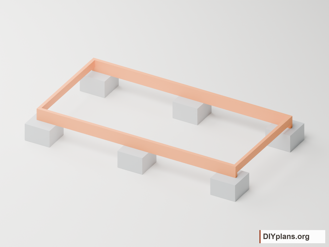
03 Join the floor frame
- Stand the two 96 in 2x6 beams on edge on the supports. Place the two outer 45 in crosspieces between them, flush with the beam ends and top edges.
- Check the outer dimensions at 96 x 48 in and equal diagonals. Clamp the frame before fastening.
- Use two 3 in exterior wood screws through each beam into each side-piece end to hold assembly alignment. Keep the end crosspieces temporarily supported until they are fastened directly to the corner posts in the post step.
- Keep both long beams seated on all three supports. Do not suspend the floor from the post bolts.
Check: The frame is square, with the end crosspieces temporarily supported and direct bearing under both beams.
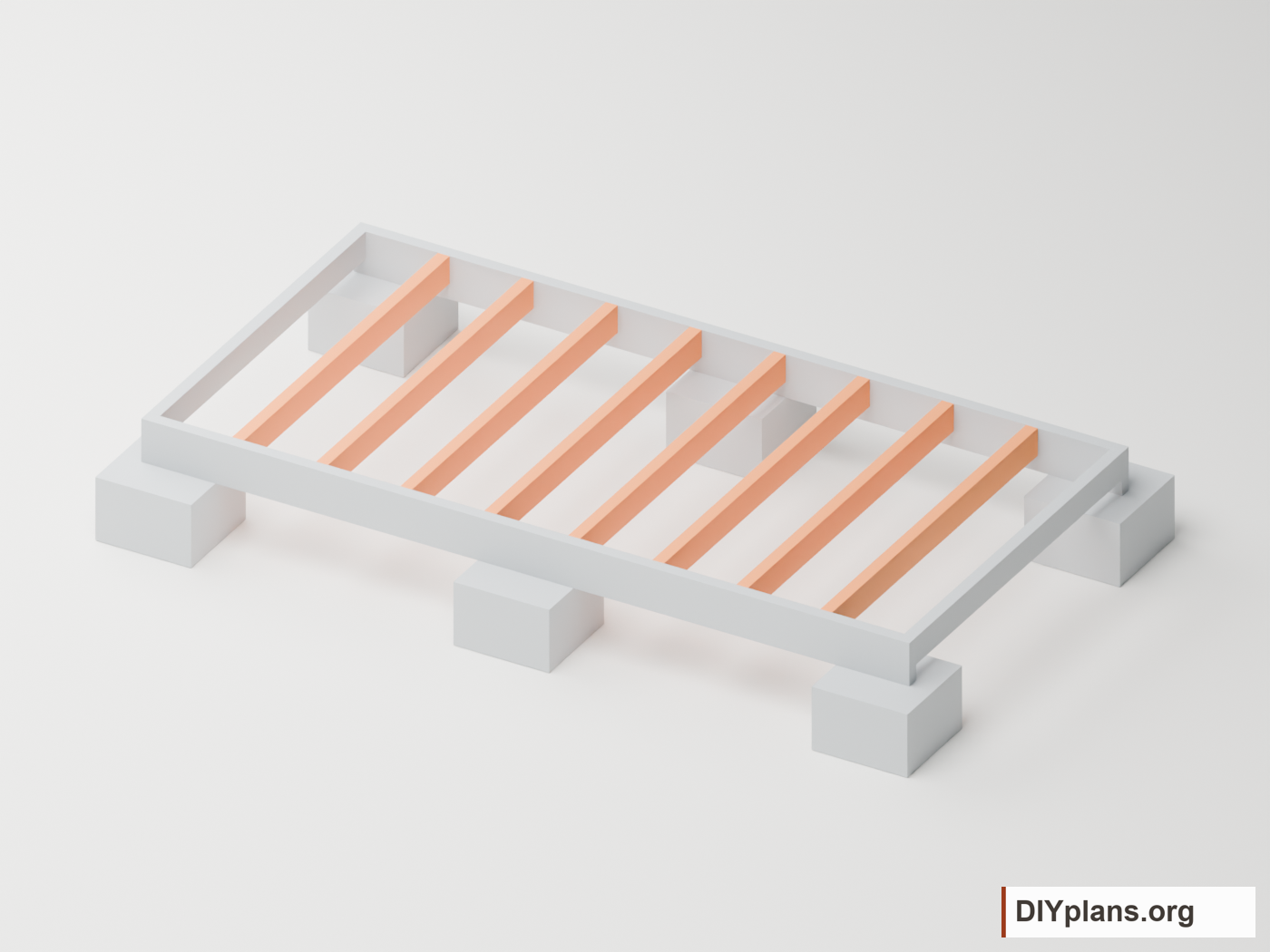

04 Install eight floor joists
- From the left beam end, mark the left edges of the interior joists at 10-1/2, 21, 31-1/2, 42, 52-1/2, 63, 73-1/2 and 84 in. Transfer identical marks to the rear beam.
- Fit a 45 in crosspiece at each mark, on edge with its top flush to the 2x6 beams. The largest center-to-center gap is 10-1/2 in.
- Install a rated 2x4 hanger at each end, 16 total. Use the exact fasteners and hole pattern approved for the selected hanger and a single 1-1/2 in thick beam. Ordinary deck screws are not hanger fasteners.
- Check the hangers do not cover the six post locations. Tighten every connection and recheck the frame diagonals.
Check: Ten crosspieces including the two ends are level at their tops, and all eight interior joists have two complete hangers.
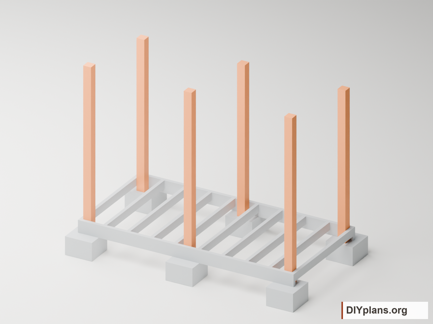

05 Fit and bolt the six posts
- Stand the three 72 in posts inside the front beam and the three 66 in posts inside the rear beam. Their left edges are 1-1/2, 46-1/4 and 91 in from the left frame end. Front posts occupy 1-1/2 to 5 in behind the front edge; rear posts occupy 43 to 46-1/2 in.
- Seat every post on its concrete support at the same elevation as the beam underside. Have a helper hold each post plumb, then clamp temporary diagonal braces before releasing it.
- On each post centerline, mark bolt centers 1-1/2 and 4 in above the beam underside. Drill straight through the 1-1/2 in beam and 3-1/2 in post for two 3/8 in through-bolts. Use the bolt maker drill clearance and end-distance requirements; do not enlarge or relocate holes casually.
- Fit a washer beneath both head and nut. Tighten the twelve 6 in bolts without crushing the wood, and confirm the nuts fully engage the threads. Recheck plumb and support bearing.
- From each outside side face, fasten the end crosspiece directly into each corner post with two No. 10 x 3 in minimum exterior structural screws, eight screws total. Put the screw line 1-3/4 in from the crosspiece end, at heights 2-3/4 and 4-3/4 in above the beam underside. This leaves 3/4 in at the upper and lower crosspiece edges and keeps the screws clear of the bolts.
- Select screws approved for this side-grain connection with 1-1/2 in embedment into the post and the stated spacing. Predrill as required. Do not remove the end-crosspiece supports or install the floor until these four joints are complete.
Check: All six posts bear on their supports, are plumb and have two tightened bolts plus temporary bracing, and all four end-crosspiece/post joints have two screws.
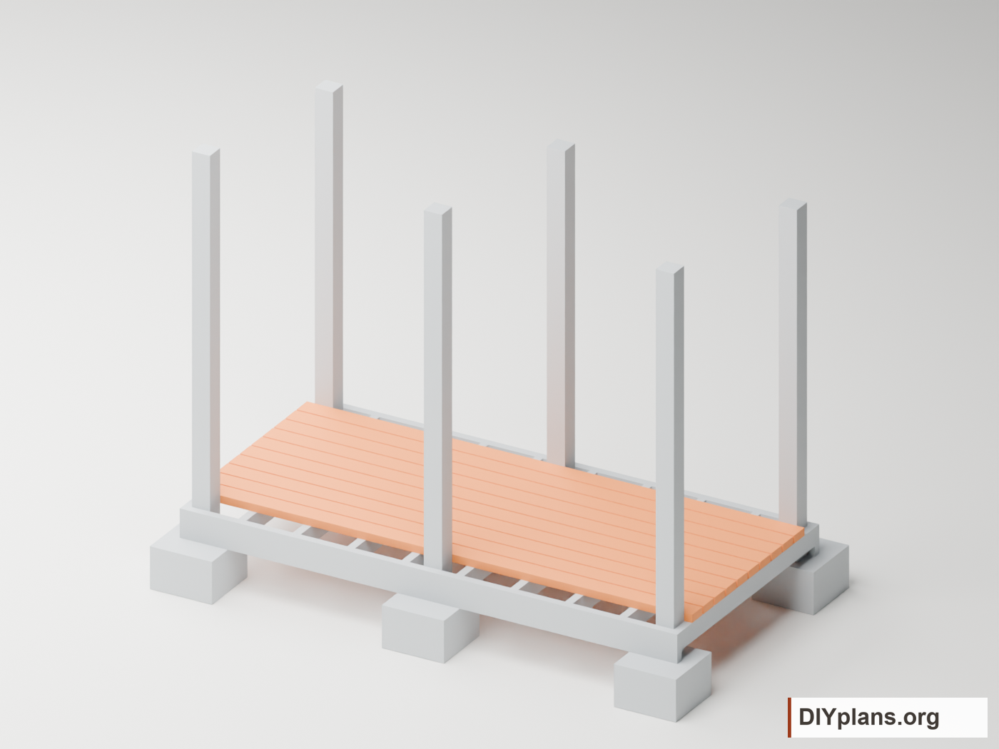
06 Lay the ventilated floor
- Lay ten 96 in 2x4 boards flat across all ten floor crosspieces. Place the front edge of the first at 5 in behind the front frame edge and the rear edge of the last at 43 in.
- Space the nine gaps evenly at 1/3 in. The boards occupy the 38 in clear space between the front and rear post rows, so no post notches are needed.
- Drive two 3 in exterior structural wood screws at every board-to-crosspiece intersection, 200 screws total. Predrill near ends, keep heads flush and avoid the joist-hanger fasteners.
- Check every board bears on all crosspieces. The floor surface is 7 in above the beam-support bearing plane.
Check: Ten boards are secure, the nine gaps are even, and no screw points protrude from the floor joints.
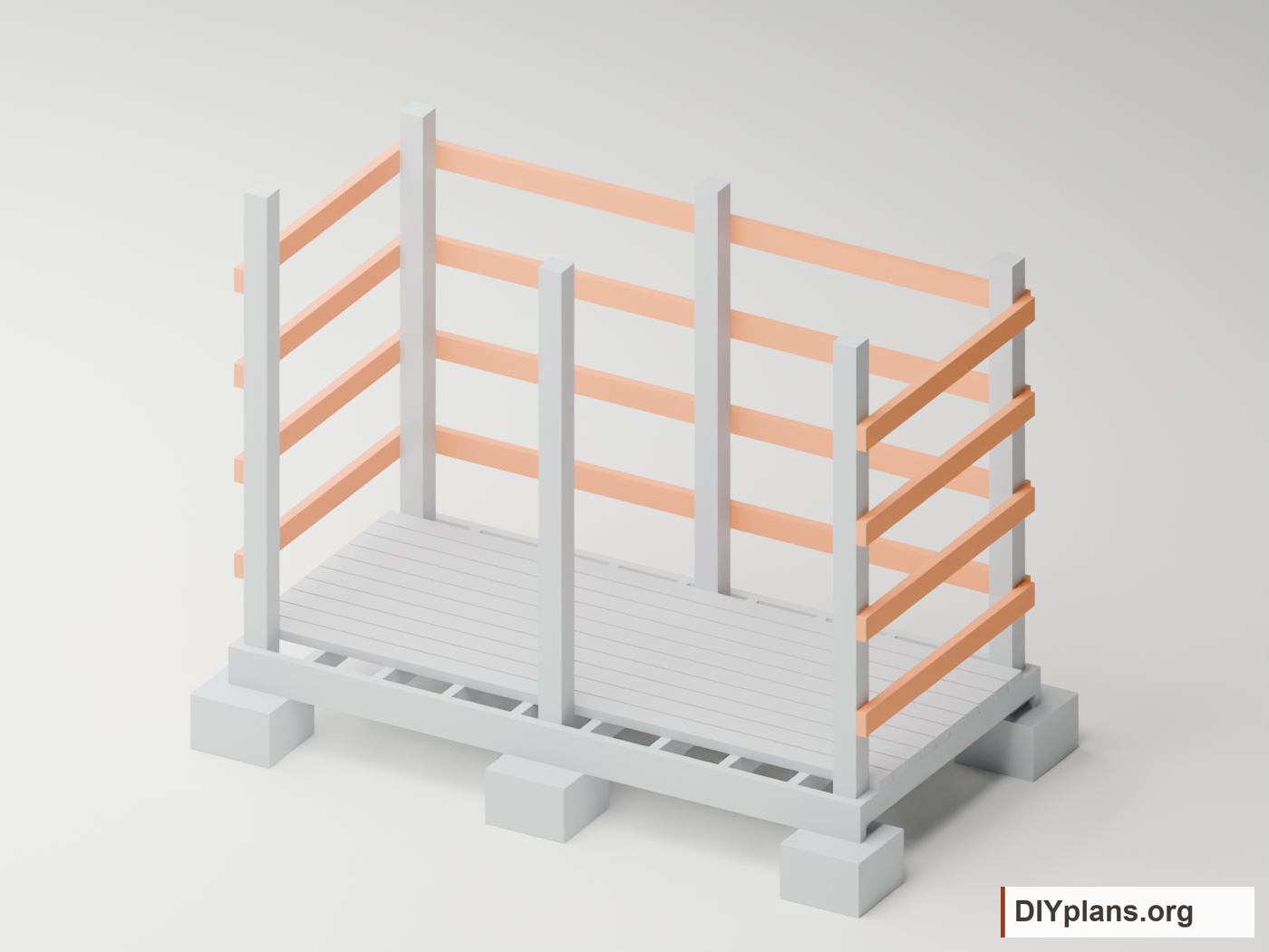
07 Fasten the side and rear slats
- Mark the bottom edges of four slat rows at 15, 29, 43 and 57 in above the beam underside. Transfer the marks to all posts.
- Fit four 93 in rear slats across the outside faces of the rear posts, starting 1-1/2 in from the left frame end. Use two 3 in screws at each of the three post crossings, 24 screws total.
- Fit four 45 in slats on each side, flush from the outside front face to the outside rear face of its post pair. Use two 3 in screws at each end, 32 screws total.
- Keep the front open. Predrill the slat ends, maintain suitable edge distances and check the posts remain plumb. Horizontal slats do not replace diagonal bracing.
Check: Twelve slats are attached at four matching elevations; every end screw enters a post.

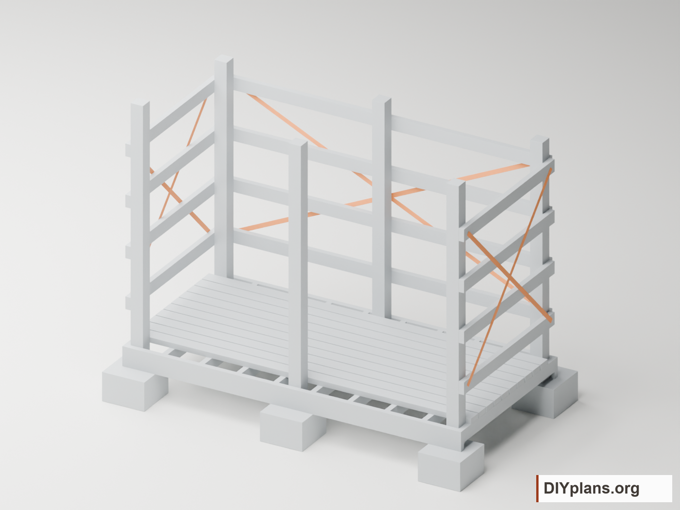
08 Brace and anchor the frame
- Install a rated opposing tension-strap system across the rear face and each side face, three X assemblies total. Use the kit instructions to position, tension and fasten the straps.
- The reference anchor rectangle on the rear is 89-1/2 in wide by 42 in high, between the corner post centers and the centers of the bottom and top slats. Each side rectangle is 41-1/2 x 42 in.
- Use only a system whose specified end fasteners develop their required embedment in the posts through the 1-1/2 in slat layer. Attach neither the ends to unsupported slat spans nor the straps with generic plumbing tape or drywall screws.
- Connect all six posts to the previously selected ground anchors. Follow the anchor installation depth, soil and connector requirements for the site. Concrete deck blocks provide vertical bearing; they do not hold the shed down against wind.
- Keep temporary braces until the permanent straps and ground anchors are complete. Stop if any post moves, a strap remains loose or a support rocks.
Check: All three X assemblies and all six ground-anchor connections are complete and taut.
09 Mark the roof slope
- Mark a line on a straight 48 in rafter that falls 6 in over a horizontal run of 41-1/2 in. The roof angle is about 8.23 degrees, or 1 3/4 in of fall per 12 in of run.
- Clamp the first rafter against the outside of the left post pair. Its top edge must pass through the downhill edge of each post top: the rear edge of the 72 in front post and the rear edge of the 66 in rear post.
- Center the 48 in sloping rafter about the 24 in frame-depth centerline. Its top front corner is about 1/4 in behind the frame front; the top rear corner is about 1/4 in ahead of the frame rear. There are no protective eaves.
- Check that neither flat post top protrudes above the rafter top plane. Transfer the same plane to the remaining rafters using a straightedge and level.
Check: The marked top plane clears every post and drops toward the rear without a hollow or twist.
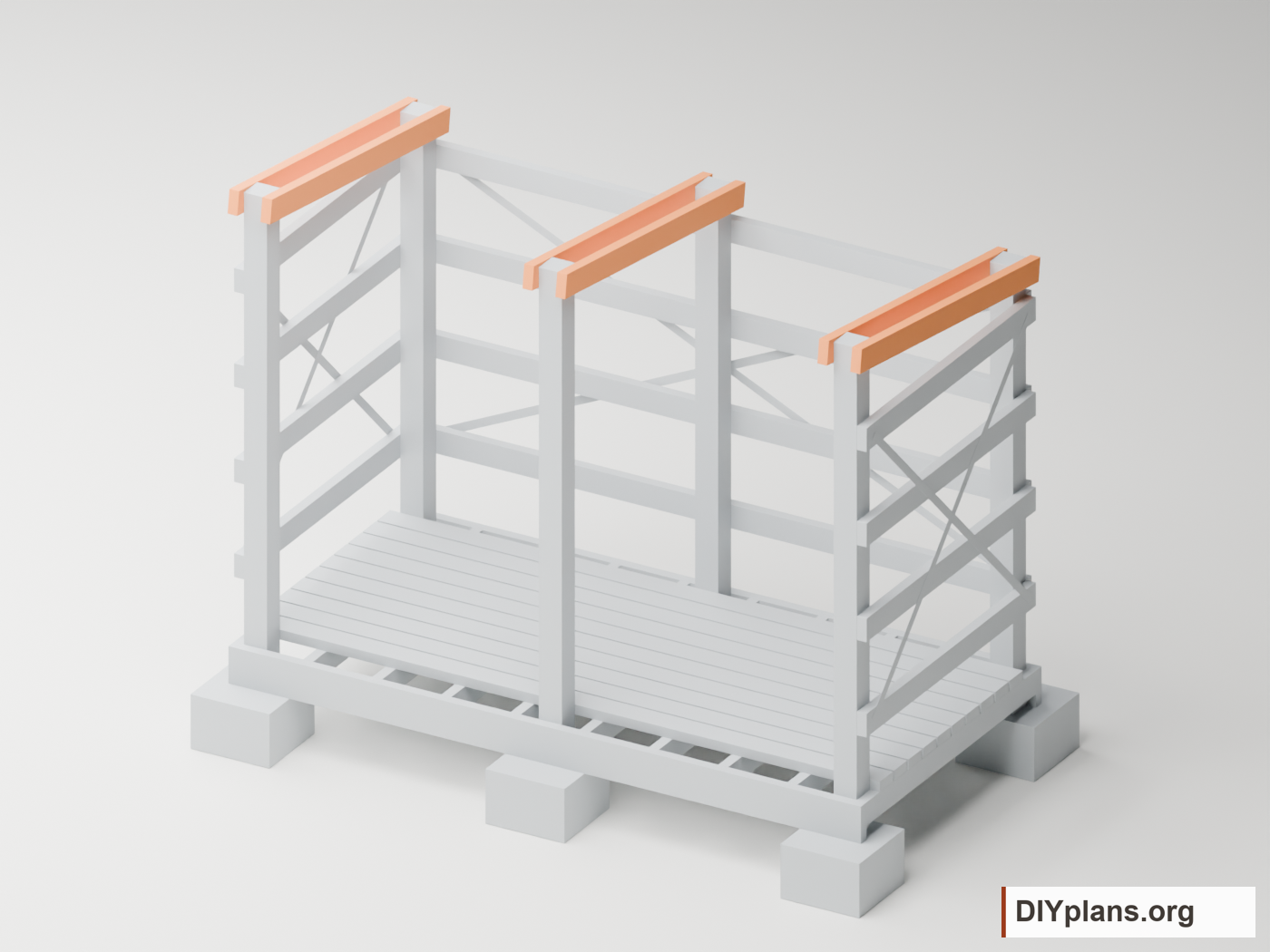
10 Fasten the paired rafters
- Fit a 48 in rafter against each side of all three post pairs, six rafters total. Across the width, their left edges are 0, 5, 44-3/4, 49-3/4, 89-1/2 and 94-1/2 in from the left frame end.
- Clamp each rafter with its top on the marked slope plane. Keep all front ends in line and all rear ends in line.
- At each post, drive two 3 in exterior structural wood screws through the rafter into the post. Use 24 screws total. Set the screws on the post centerline with sound wood above and below, following the selected screw maker spacing and edge-distance requirements.
- Lay a straightedge across all six rafters at front, middle and rear. Correct any high or low member before fitting the roof sheet.
Check: All six rafters have two complete post connections and form one flat roof plane.
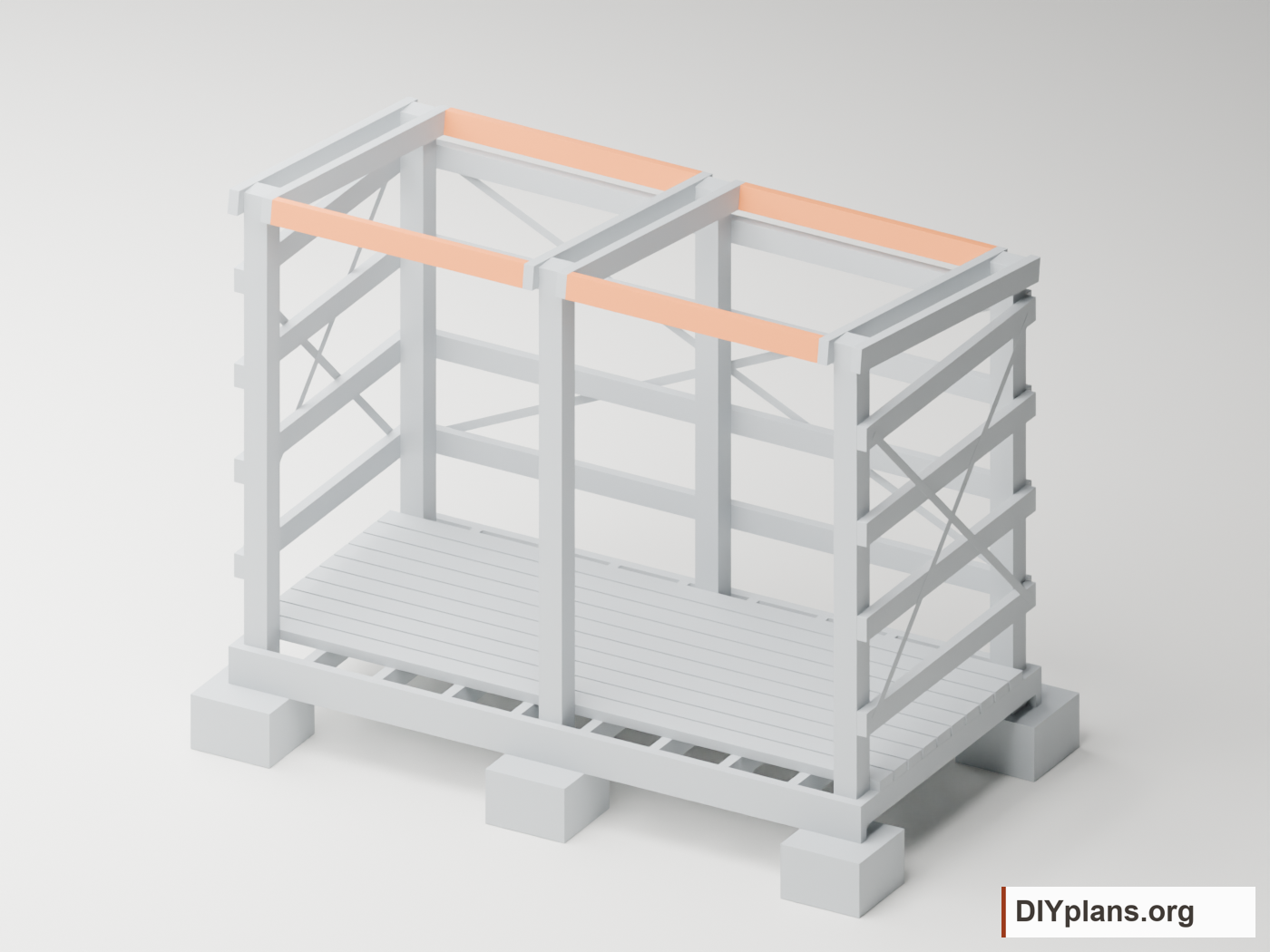
11 Support the roof-sheet edges
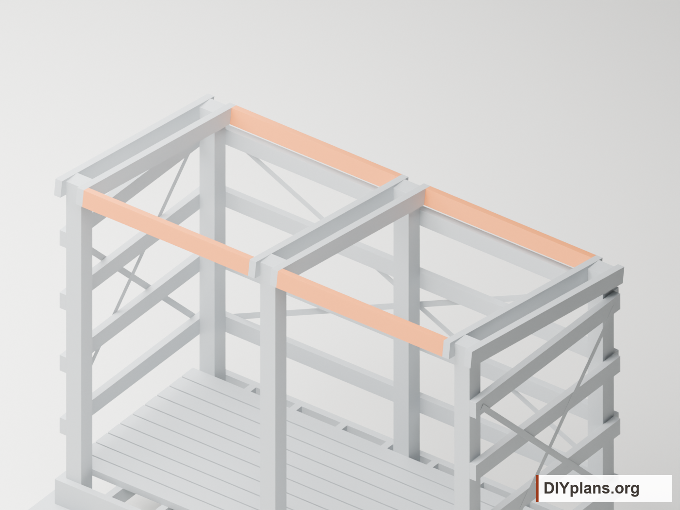
- Fit two 38-1/4 in roof blocks across the front ends and two across the rear ends of the rafters. They bridge the large gaps from x 6-1/2 to 44-3/4 in and from x 51-1/4 to 89-1/2 in.
- Rotate each block section to match the 8.23 degree roof slope. Its top face must be flush with the rafters and its outside face flush with the square rafter ends. Keep the block width within the first or last 1-1/2 in along the roof slope.
- Predrill and drive two 3 in exterior wood screws through each adjacent rafter into each block end, 16 screws total. Follow the screw maker requirements for end-grain connections.
- Leave the three short 3-1/2 in gaps within the rafter pairs clear of the posts. The four blocks support the long unsupported stretches of panel edge.
Check: All four blocks are fixed flush to the roof plane and have no interference with the posts.
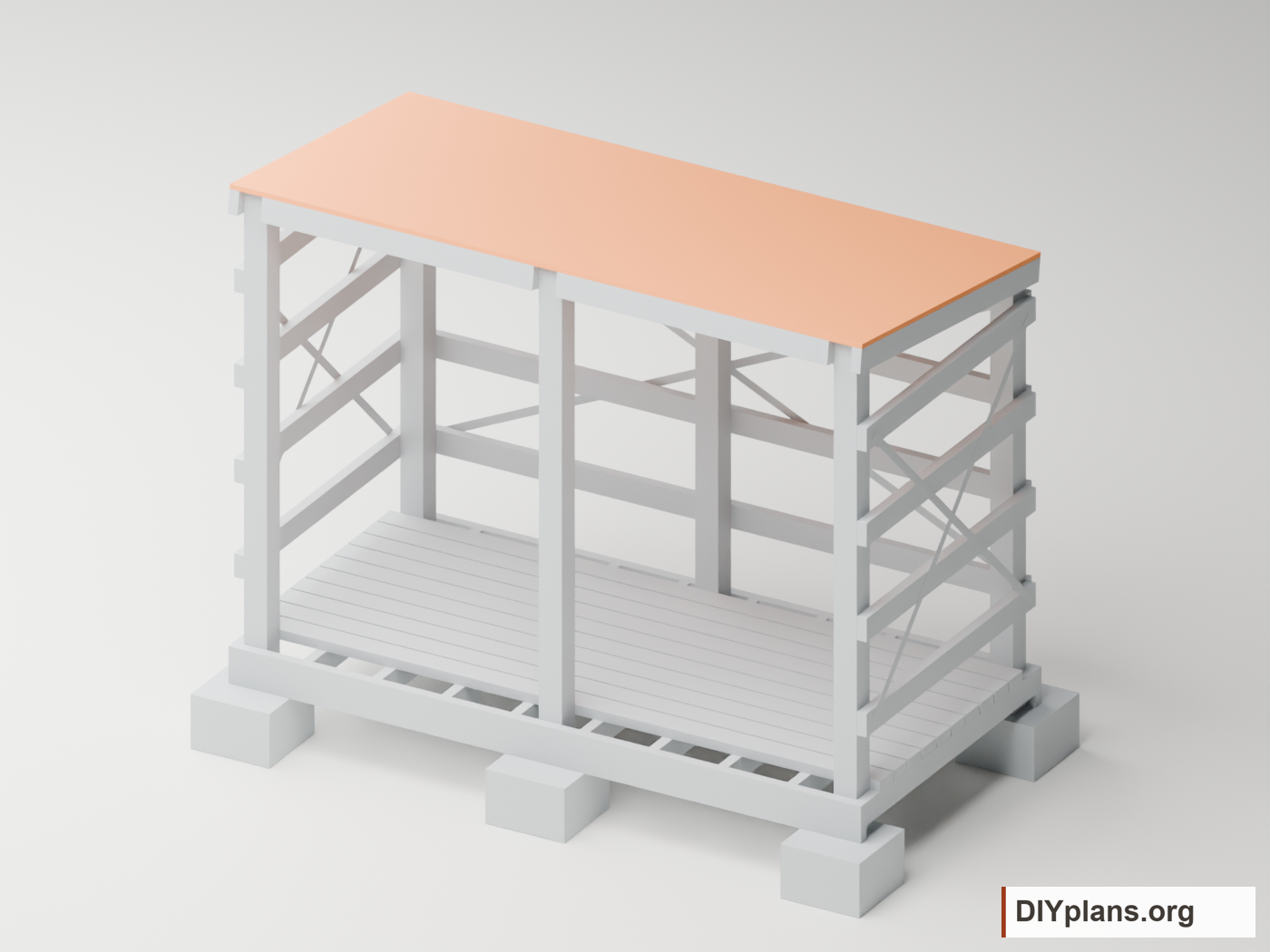
12 Fasten the roof deck
- Use one 4 x 8 ft plywood sheet marked 23/32 Performance Category and roof span 48/24, with exterior-bond suitability for the chosen roof system. Do not substitute a generic 1/2 in sheet.
- With a helper, place the 96 in strength-axis direction across the rafters and the 48 in direction down the roof slope. Align all edges with the modeled roof perimeter.
- Mark the six rafter lines and four blocking lines on the sheet. Fasten with approved exterior roof screws at no more than 6 in spacing along each support, or closer if the selected sheet/roof/load instructions require it. Keep heads flush without breaking the surface.
- Work from stable ladders or platforms. Do not stand on this small roof. Check the roof is flat, every edge is supported as drawn and no fastener point has missed its member.
Check: The correct grade sheet is secure and flat, with its strength axis across the rafters.
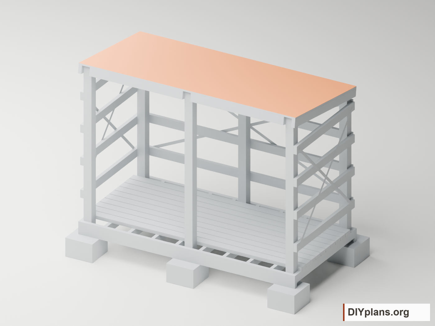
13 Finish the low-slope roof
- Let the plywood meet the membrane manufacturer dryness and surface requirements. Remove dirt and sharp projections; prepare corners and edges as the system directs.
- Install a single-piece low-slope EPDM membrane system approved for plywood at a 1.73:12 slope. A 5 x 9 ft sheet allows trimming and perimeter detailing around the 4 x 8 ft deck.
- Use that system's adhesive, edge metal, termination tape, corner details and fasteners for the full 24 ft perimeter. Wrap and seal the edges as instructed, keeping drainage open at the lower rear edge.
- Follow the adhesive ventilation, temperature and curing requirements. Generic paint or an unspecified liquid coating is not the roof covering in this plan. The CAD membrane is a thin top-face schematic; edge metal, turns and adhesive are not modeled.
Check: The sheet is bonded and terminated all around, with no exposed plywood edge or obstructed rear drainage.
14 Inspect before stacking wood
- Check every support bears, every post is plumb, both beams remain straight, and the bracing and ground anchors are complete. Recheck bolts after the treated wood dries and periodically in use.
- Stack split firewood evenly across the floor. Keep stacks self-supporting, clear of the roof and below the top slat. Do not lean unstable piles against the side or rear slats.
- Keep ventilation gaps open and preserve front access. This compact roof has no eaves; driving rain can wet exposed wood, so choose the site and stacking position accordingly.
- Inspect for loose fasteners, split timber, settlement, sagging or membrane damage. Unload the shed before correcting movement or damaged parts.
- This is an unbuilt design with no established firewood-load, snow or wind rating. Confirm suitability for local conditions before construction. Do not climb the structure or use it as occupied shelter.
Check: The empty structure is stable and all fasteners, anchors and roof edges pass inspection before loading.