Before you start
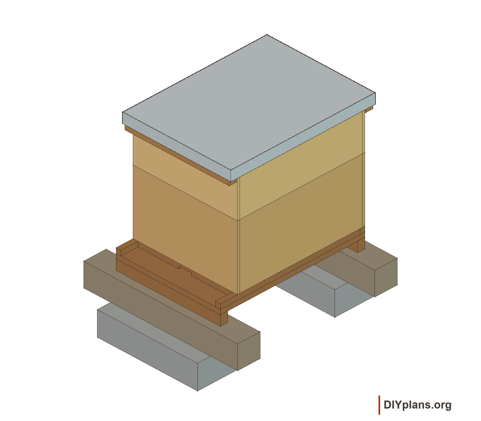
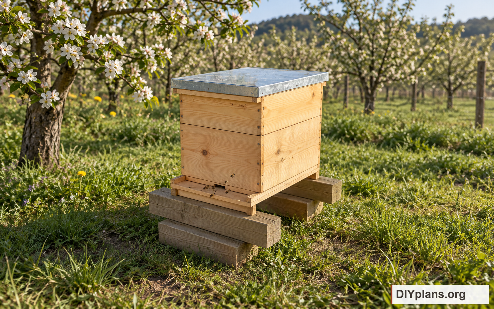
- This is a woodworking build for a beekeeper, with one deep box and one medium super. Commercial frames and foundation are required. The editable CAD includes 20 wooden pieces, two solid concrete blocks and one formed metal cap; frames, screws, coatings, hems, corner tabs and strap are specified in the guide but not modeled.
- All construction dimensions are in inches; FreeCAD stores millimeters internally. Use measured 3/4 in lumber and nominal 3/4 in exterior plywood (23/32 in modeled). Dry-fit actual frames before machining all rests.
- Use a sheltered site and firm, well-drained ground. The support detail is for centered hive loads; no whole-hive, soil, wind or anchorage rating is asserted. This design has not been physically prototyped.
- Plan safe lifting and beekeeper training before occupancy. One deep plus one medium is not a universal year-round colony capacity.
Dimensions and opening sizes
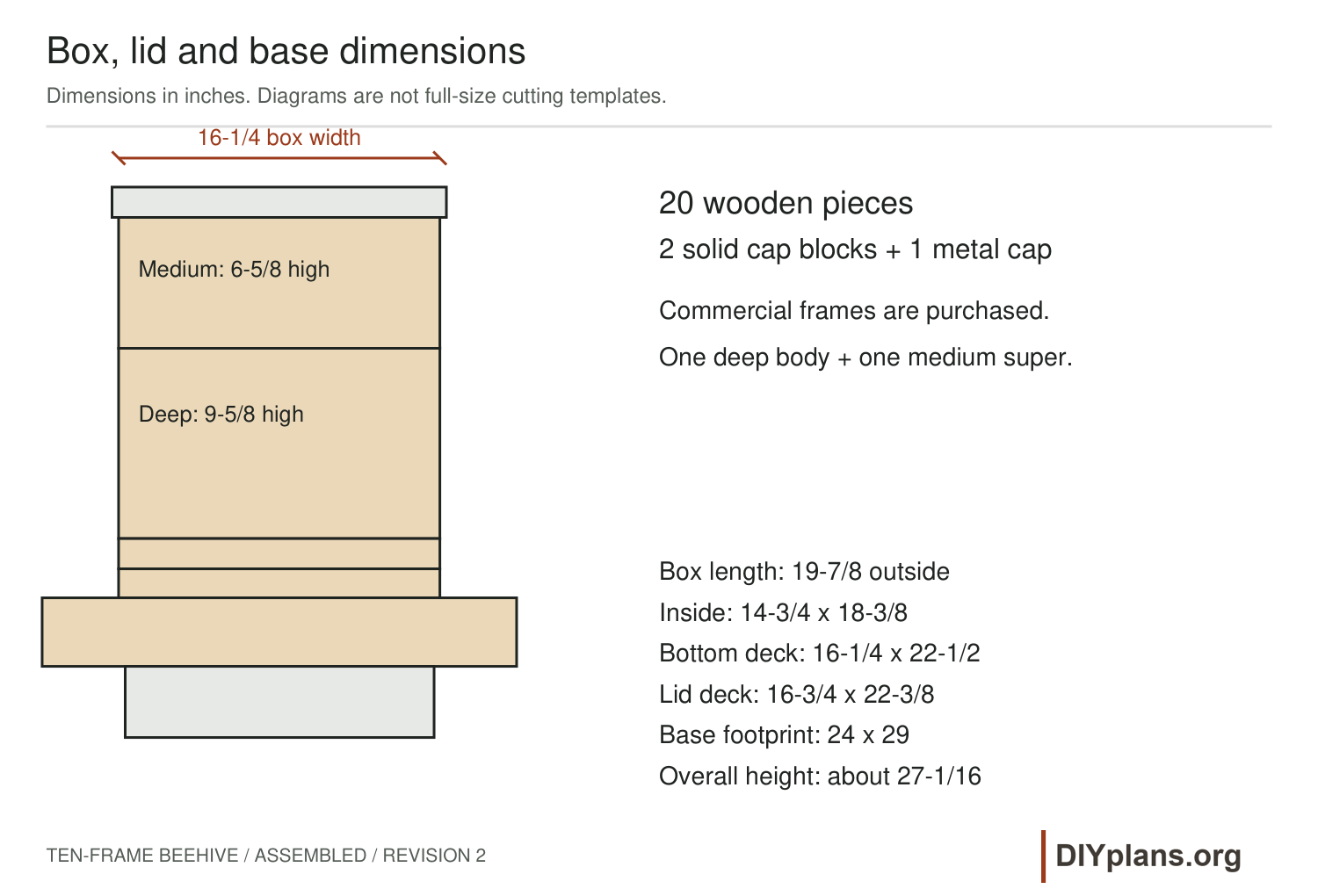
- Box widthOutside dimension
- 16 1/4 in
- Box lengthOutside dimension
- 19 7/8 in
- Base widthIncluding cedar rails
- 24 in
- Base lengthIncluding solid blocks
- 29 in
- Overall heightLevel nominal assembly; base pads set with slight forward drainage fall
- 27 1/16 in
- Deep box heightFor 9-1/8 in commercial deep frames
- 9 5/8 in
- Medium box heightFor 6-1/4 in commercial medium frames
- 6 5/8 in
Shopping list
| Buy | Material | Stock size |
|---|---|---|
| 1 board | Clear dry untreated pine | 1 x 12 x 8 ft; actual 3/4 x 11-1/4 in |
| 1 board | Clear dry untreated pine | 1 x 8 x 8 ft; actual 3/4 x 7-1/4 in |
| 1 board | Clear dry untreated pine | 2 x 2 x 8 ft; actual 1-1/2 in square |
| 1 panel | Exterior-bond plywood | 24 x 48 in; nominal 3/4 in |
| 1 sheet | Aluminum flashing | 24 x 36 in; 0.4826 mm thick |
| 1 timber | No. 2 or better Western Red Cedar | 4 x 4 x 8 ft; actual 3-1/2 in square |
| 2 blocks | Solid ASTM C90 concrete cap | Actual 15-5/8 x 7-5/8 x 3-5/8 in |
| 10 | Assembled Hoffman frames with matching foundation | US Langstroth deep; 9-1/8 in high; 19 in top bar |
| 10 | Assembled Hoffman frames with matching foundation | US Langstroth medium; 6-1/4 in high; 19 in top bar |
| 40 | Stainless flat-head wood screws | #8 x 1-1/2 in |
| 25 | Stainless flat-head wood screws | #8 x 1-3/4 in |
| 20 | Stainless flat-head wood screws | #8 x 1-1/4 in |
| 10 | Stainless pan-head screws | #8 x 3/4 in |
| 10 | EPDM bonded sealing washers | Sized for #8 screws |
| 1 bottle | Type I exterior wood glue | 8 oz bottle |
| 1 roll | Butyl sealing tape | 1/2 in wide x 1/16 in thick x 10 ft |
| 1 can | Exterior water-based wood primer | 1 quart |
| 1 can | Light-colored exterior water-based paint | 1 quart |
| 1 | Outdoor UV-resistant hive strap with cam buckle | At least 10 ft long x 1 in wide |
Quantity notes
Full stock sizes include 1/8 in cutting kerf and 1/4 in end trimming. Fastener quantities include spares.
- Clear dry untreated pine, 1 x 12 x 8 ft; actual 3/4 x 11-1/4 in: Deep box plus all four bottom strips from the long rip offcut. Reject loose knots, splits and twist.
- Clear dry untreated pine, 1 x 8 x 8 ft; actual 3/4 x 7-1/4 in: Medium box; rip to 6-5/8 in.
- Clear dry untreated pine, 2 x 2 x 8 ft; actual 1-1/2 in square: Rip to 1-1/8 x 1-1/2 in; four cleats.
- Exterior-bond plywood, 24 x 48 in; nominal 3/4 in: Model uses 23/32 in. Measure actual thickness. No MDF, OSB or treated interior panels.
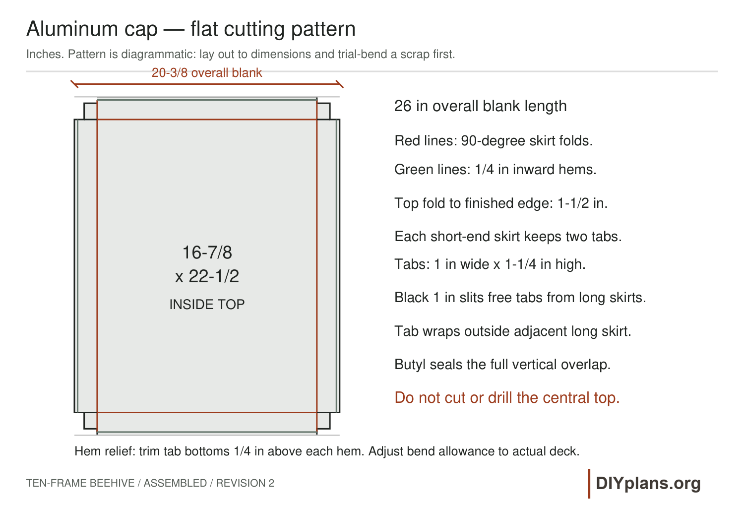
- Aluminum flashing, 24 x 36 in; 0.4826 mm thick: One 20-3/8 x 26 in blank; folding tabs and hems included.
- No. 2 or better Western Red Cedar, 4 x 4 x 8 ft; actual 3-1/2 in square: Two 24 in rails. Sound full section at bearings; no large splits or decay.
- Solid ASTM C90 concrete cap, Actual 15-5/8 x 7-5/8 x 3-5/8 in: Solid units laid on the broad face. Do not substitute hollow or damaged blocks.
- Assembled Hoffman frames with matching foundation, US Langstroth deep; 9-1/8 in high; 19 in top bar: Top-bar hanging ears 5/16 to 3/8 in thick; dry-fit before cutting all frame rests.
- Assembled Hoffman frames with matching foundation, US Langstroth medium; 6-1/4 in high; 19 in top bar: Use the same hanging-ear thickness as the deep frames. This is a medium box.
- Stainless flat-head wood screws, #8 x 1-1/2 in: 28 installed at box corners; remaining screws are spares.
- Stainless flat-head wood screws, #8 x 1-3/4 in: 16 installed through plywood into cleats; remaining screws are spares.
- Stainless flat-head wood screws, #8 x 1-1/4 in: 11 installed through bottom strips; remaining screws are spares.
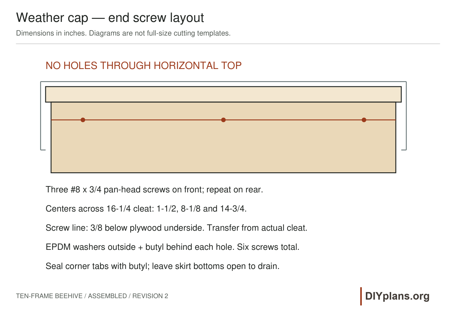
- Stainless pan-head screws, #8 x 3/4 in: Six installed horizontally into lid end cleats. No fastener through the roof top.
- EPDM bonded sealing washers, Sized for #8 screws: Six installed under the cap screw heads.
- Type I exterior wood glue, 8 oz bottle: Apply to wood joints, not removable hive interfaces; follow product temperature and cure instructions.
- Butyl sealing tape, 1/2 in wide x 1/16 in thick x 10 ft: Seal four vertical corner laps and six screw penetrations; trim surplus without blocking skirt drainage.
- Exterior water-based wood primer, 1 quart: Exterior surfaces and exposed plywood edges; follow label coverage and curing.
- Light-colored exterior water-based paint, 1 quart: Two exterior coats if required by label. Keep box interiors and frame contact surfaces bare.
- Outdoor UV-resistant hive strap with cam buckle, At least 10 ft long x 1 in wide: Wrap across the hive width around lid and bottom board. Holds the stack together; does not anchor it to ground.
Required installation supplies
- Obtain commercial frames with matching 5/16 to 3/8 in hanging ears and verify fit before machining all rests.
- Use actual 3/4 in dry pine and measure nominal 3/4 in exterior plywood.
- Use sound No. 2 or better Western Red Cedar rails and solid ASTM C90 cap blocks to the listed actual dimensions.
Optional material depending on installation
- The included low base requires firm, fully bedded pads in a sheltered location. Quantify pad aggregate for the site.
- A hive strap retains the stack. Exposed sites need a local anchorage design; no wind rating is established.
Tools & equipment
- Table saw or track saw with stable stock support
- Router table or dado setup with guards and push sticks
- Drill/driver, 11/64 in clearance bit, 7/64 in pilot bit and countersink
- Tape measure, square, calipers, straightedge and level
- Bar clamps, sanding block and dust extraction
- Tin snips, sheet-metal brake or clamped straight battens and wood mallet
- Eye and hearing protection, dust respirator and cut-resistant gloves for sheet metal
- Paintbrush, water-test container and pad-compaction tools
BEFORE YOU BUILD
Use this work at your own risk
No person or organization makes any guarantee or warranty, express or implied, regarding this design, its documentation, digital files, or website views. They are not professional services and do not create an architect-client or other professional-client relationship. No promise is made about accuracy, completeness, reliability, code compliance, or fitness for your project.
Buildings and building projects are complex, and many things can go wrong. You are responsible for checking dimensions and site conditions, choosing suitable materials and methods, obtaining permits, following codes and manufacturer instructions, and getting qualified professional help when needed. To the fullest extent permitted by law, DIYPlans.org disclaims liability for damages resulting from use of this work. Read the FAQ about your responsibilities.
CC CC BY-NC-SA 4.0 InternationalShare and adapt this free design for noncommercial purposes with appropriate credit. Link to the license, indicate changes, and license adaptations under the same terms.
Instructions
01 Measure frames and cut the stock
- Use the cut list in inches. Nominal lumber names are shopping sizes; machine to the listed actual sizes. Measure the plywood and set PlywoodThickness in the CAD if it differs from 23/32 in. Do not change box dimensions to suit nominal board widths.
- Obtain all 20 frames before machining the frame rests. Confirm 19 in top bars, 9-1/8 in deep frames, 6-1/4 in medium frames, and matching hanging ears 5/16 to 3/8 in thick. Dry-fit a sample joint and actual frames before repeating the cuts.
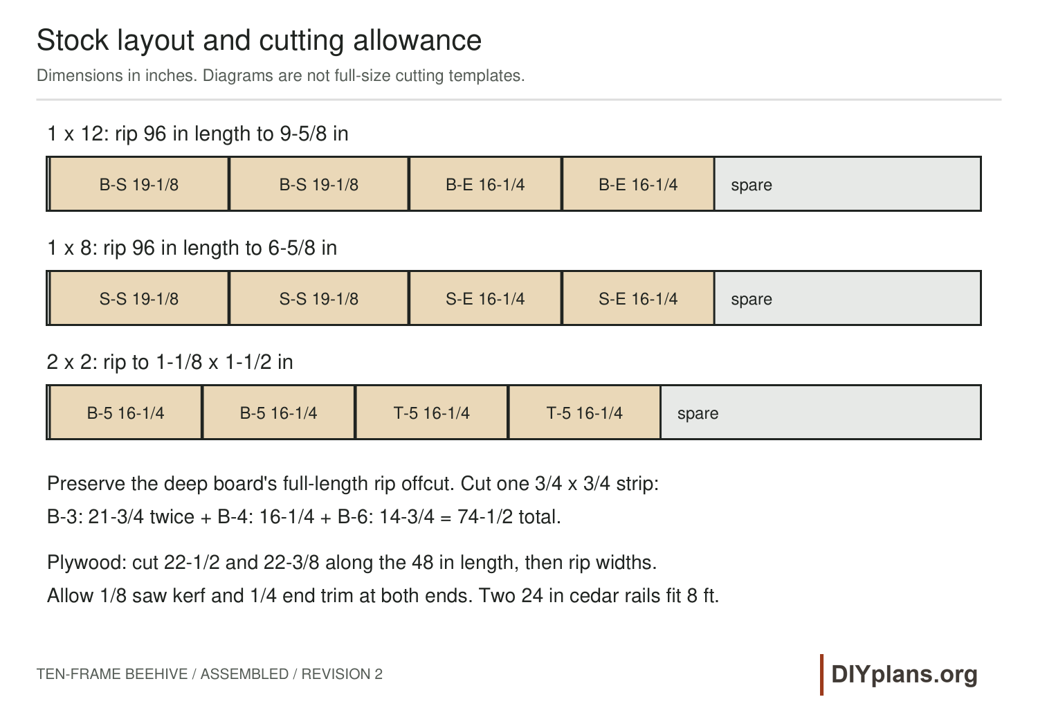
- Allow 1/8 in saw kerf and 1/4 in end trim at both ends. Rip the full 1 x 12 to 9-5/8 in first; preserve its approximately 1-1/2 in wide, 96 in long offcut. Rip one 3/4 in wide strip from that offcut for B-3, B-4 and B-6.
- Crosscut two 19-1/8 in and two 16-1/4 in deep boards. Repeat in the 1 x 8 ripped to 6-5/8 in. Rip the 2 x 2 to 1-1/8 x 1-1/2 in and cut four 16-1/4 in cleats. Cut the plywood and two cedar rails to the schedule.
- Support full sheets and long stock. Use guards, push sticks, eye/hearing protection and dust extraction. Sand splinters without rounding the box mating edges.
Check: All quantities match the cut list; paired sides and ends are equal; actual frames and plywood thickness are recorded.
02 Cut the end-board rabbets
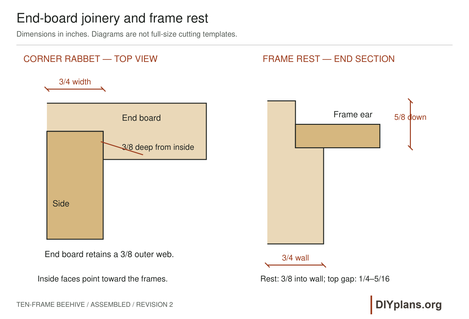
- Mark the inside face and top edge of all four end boards. On the inside face, cut a 3/4 in wide by 3/8 in deep rabbet along each vertical end. The remaining outer web is 3/8 in thick. The square-ended side boards nest in these rabbets.
- Across the inside top edge of each end board, cut the frame rest 3/8 in horizontally into the 3/4 in thickness and 5/8 in down from the rim. Leave a clean, continuous bearing ledge. Use a router table or supported dado setup, make shallow passes and clamp securely.
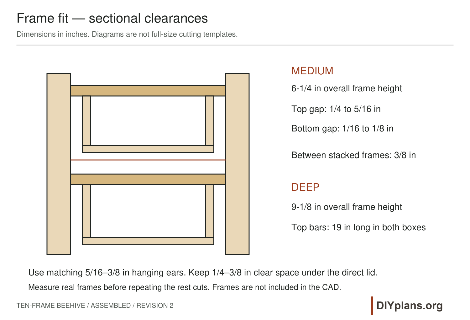
- Clamp one box around real frames before machining the other pair. Inside box dimensions are 14-3/4 x 18-3/8 in; the opposed frame-rest pockets span 19-1/8 in. A centered 19 in top bar has 1/8 in total end clearance and 5/16 in bearing on each ledge.
- The top of a seated frame must be 1/4 to 5/16 in below the rim. The 5/8 in rest depth assumes 5/16 to 3/8 in hanging ears. Do not add metal rests or an inner cover without recalculating the resulting gaps.
Check: End-board rabbets face inward; actual frames hang on both ledges, clear the ends and sit 1/4 to 5/16 in below the rim.
03 Glue and screw the deep and medium boxes
- Assemble each box on a flat surface with a light coat of exterior wood glue in the four corner rabbets. Clamp to 16-1/4 in outside width and 19-7/8 in outside length. Match the two diagonal measurements within 1/16 in; keep upper and lower edges flush.
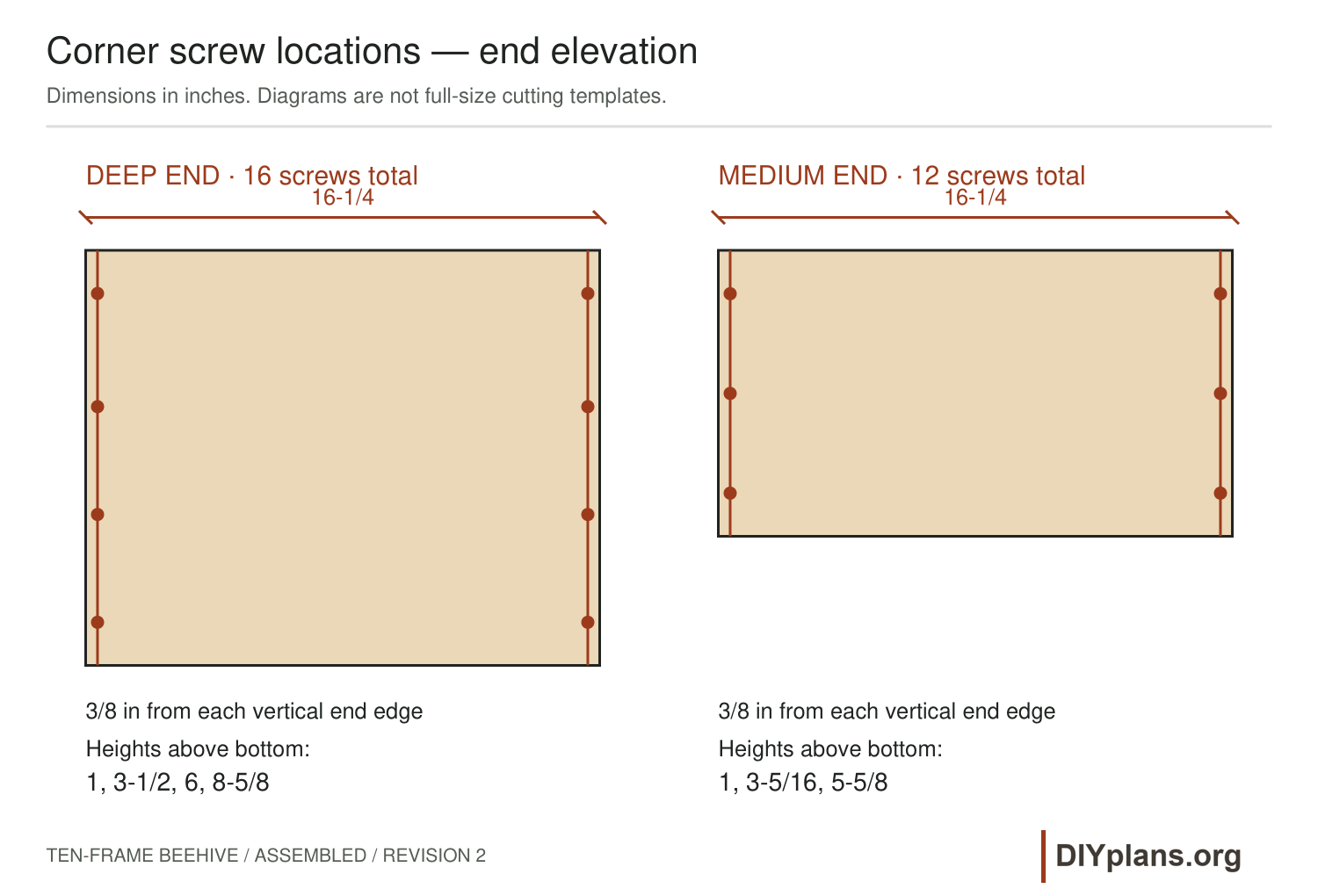
- Drive #8 x 1-1/2 in stainless flat-head screws through each end board into the end grain of the side board. Screw centers are 3/8 in from each side edge of the end board. Deep box: four at each corner, 1, 3-1/2, 6 and 8-5/8 in above the bottom (16 screws). Medium: three at each corner, 1, 3-5/16 and 5-5/8 in above the bottom (12 screws).
- Clamp the joint while drilling. Use an 11/64 in clearance hole through the first member and a 7/64 in pilot in soft pine, or the screw maker's specified pilot. Drill pilots slightly deeper than penetration. Countersink only enough to seat flush in the 3/8 in web; test on scrap and do not overtighten.
- Allow the glue to cure per its label. Stack the boxes on a flat board and confirm continuous contact, without rocking or open corners. Keep the two boxes separable; never glue their mating rims together.
Check: Both boxes are square, fastener heads are flush, no joints are split and the stacked rims meet without rocking.
04 Build the bottom board and reducer
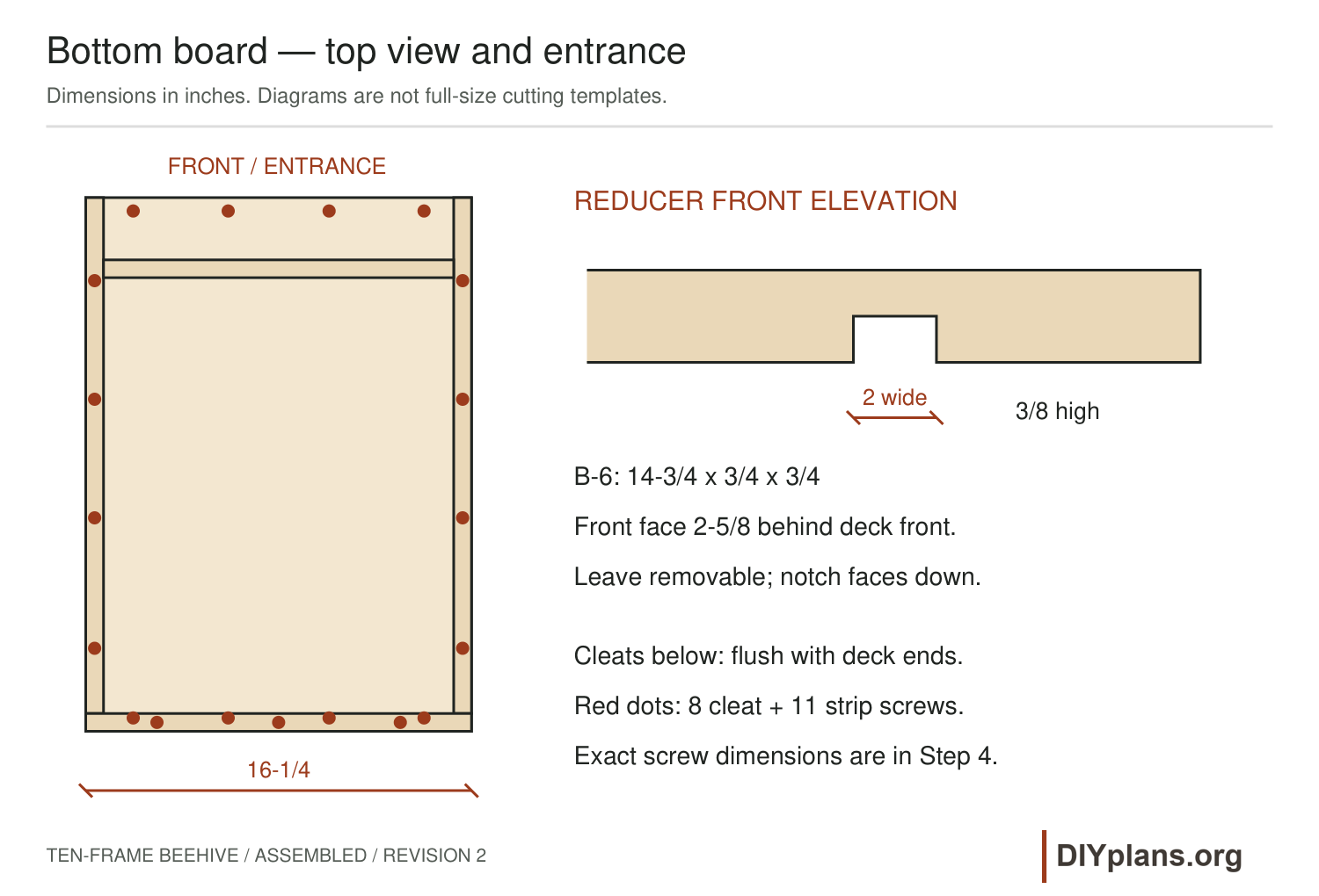
- Place B-1 with the 16-1/4 in width across the entrance and 22-1/2 in length front-to-back. Under it, glue the two B-5 cleats flush with the front and rear edges. Each spans the full width, with 1-1/2 in vertical depth and 1-1/8 in fore-aft width.
- Secure each cleat from the plywood top with four #8 x 1-3/4 in screws. Across the deck, centers are 2, 6, 10-1/4 and 14-1/4 in from the left edge; fore-aft centers are 9/16 in from the front and rear edges. Clearance-drill the plywood, pilot-drill the cleats, and countersink flush.
- Glue B-3 side strips on top, flush with the two sides and front. Fit B-4 across the full width at the back, behind the side strips. Use #8 x 1-1/4 in screws: four per side, 3-1/2, 8-1/2, 13-1/2 and 19 in from the front, on strip centerlines. Put three in B-4 at 3, 8-1/8 and 13-1/4 in from the left edge, on its centerline.
- Cut the reducer B-6 bottom notch 2 in wide x 3/8 in high, centered on its 14-3/4 in length and through its 3/4 in thickness. Sand smooth. Place it between the side strips with its front face 2-5/8 in behind the deck front, directly under the deep front wall. Leave it removable.
- Dry-stack the deep box with its rear flush to the deck rear. Confirm it bears on the three fixed strips and reducer, and the notch opens to the landing board. Remove the reducer when ventilation or colony traffic requires a wider entrance.
Check: The 2 x 3/8 in entrance is unobstructed; the reducer lifts out; no screw tips project through the plywood; the box sits flat.
05 Make the lid deck and locating cleats
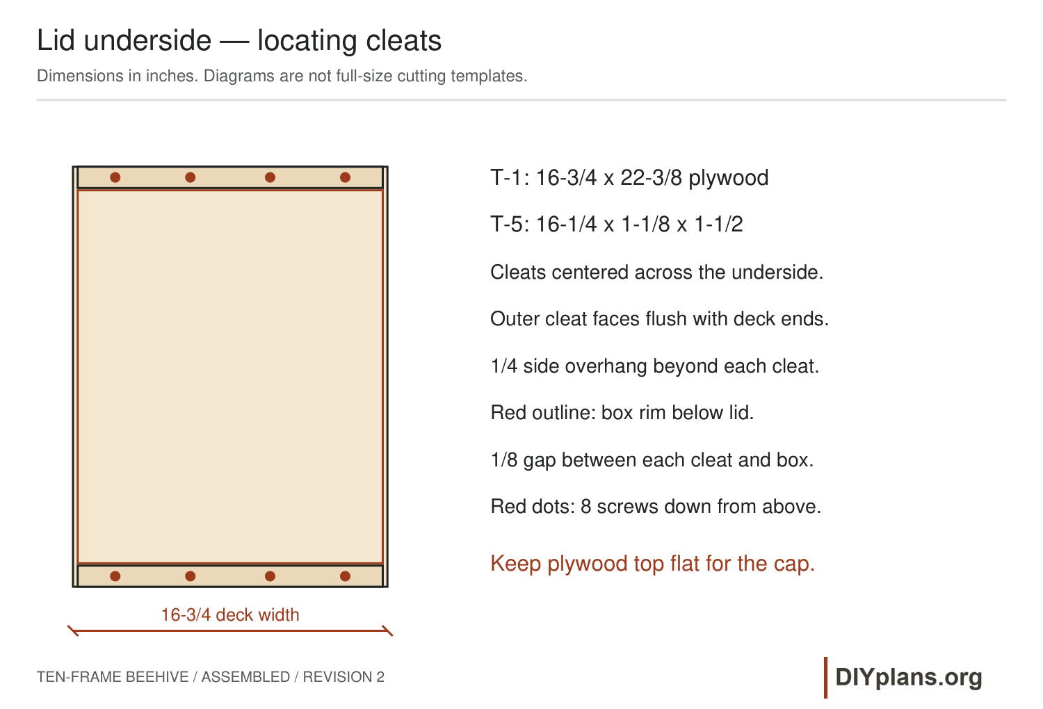
- Place T-1 with the 16-3/4 in width across the hive. Center the 16-1/4 in long T-5 cleats across its underside, leaving 1/4 in of deck beyond each cleat end. Set the outer face of each cleat flush with the front or rear deck edge.
- Glue and clamp the cleats. Use four #8 x 1-3/4 in flat-head screws per cleat, driven down through the plywood on a line 9/16 in from the respective end. Locate screws 2, 6, 10-1/4 and 14-1/4 in from the left end of each 16-1/4 in cleat (add 1/4 in when measuring from the deck edge). Clearance-drill the plywood and pilot-drill the pine.
- Test on the medium box. The plywood underside rests on the rim. The cleats hang outside the box ends, with 1/8 in clearance at each end when centered; the plywood overhangs each side by 1/4 in. Do not add strips above the deck.
- Before fitting the metal cap, prime and paint all lid plywood cut edges and outer wood faces, including the top face that the cap will conceal. Let the finish fully cure. Keep the underside over the frames bare.
- Keep the lid removable. This cover sits directly over the frame top space, without an inner cover. Sand sharp wood edges lightly and confirm the frame tops do not touch the underside.
Check: The lid lowers and lifts freely; its deck rests on the rim and both locating cleats clear the box ends by 1/8 in.
06 Cut and hem the aluminum cap
- Use gloves and eye protection when handling flashing. Mark a 20-3/8 x 26 in blank on the 0.4826 mm aluminum sheet. The central inside-top panel is 16-7/8 x 22-1/2 in. From each outside edge, mark a hem line at 1/4 in and a skirt fold line at 1-3/4 in.
- Follow the cap pattern: retain the central top and four side skirts. At each corner, keep a 1 in wide tab attached to a short-end skirt; remove the rest of the 1-3/4 in corner square. Tabs extend from the top fold down 1-1/4 in and stop above the hem. Cut a 1 in slit between each tab and the adjacent long skirt, ending exactly at the top-panel corner; the tab remains attached only to its short-end skirt. Do not cut into the top panel.
- Fold the outer 1/4 in edge of each skirt inward nearly flat to make a safe hem, using a sheet-metal brake or straight clamped battens and a wood block. Relieve hem ends so the corner tabs can fold without a thick four-layer lump.
- Trial-bend a scrap strip first. Fold both long skirts down 90 degrees, then the short-end skirts. Fold the retained tabs around the outside of the long skirts. Adjust the bend lines for the tooling bend radius so the finished inside top remains at least 16-7/8 x 22-1/2 in; verify over the real deck before final creasing.
Check: The cap fits over the deck with at least 1/16 in clearance per edge, 1-1/2 in finished skirts, smooth hems and four intact overlapping corner tabs.
07 Seal and fasten the weather cap
- Place a continuous strip of butyl tape between each outside corner tab and the adjacent long skirt, covering the vertical lap from the top corner down to the tab bottom. Press each lap firmly shut. Leave the bottom of the skirt open for drainage; no screw or cut goes through the horizontal top.
- Center the cap on the dry lid deck. Fix only through the front and rear skirts into the pine T-5 cleats. Put three screw centers on each end, 1-1/2, 8-1/8 and 14-3/4 in from the left end of the 16-1/4 in cleat. Set the line 3/8 in below the plywood underside. Transfer marks from the actual cleat, not the cap edge.
- Drill 11/64 in clearance through the aluminum and 7/64 in pilot holes into the cleat. Put a small butyl patch behind each penetration. Use six #8 x 3/4 in pan-head screws with EPDM bonded washers. Tighten just enough to compress the washers; do not crush the seal or dimple the cap. Use no screws into unsupported side skirts.
- With the empty lid raised on blocks, pour water over its top and inspect the underside and corner laps. Correct leaks before installation. The CAD shows the cap envelope; the hems, corner tabs, sealant and fasteners are detailed here and are not separate CAD solids.
Check: All four corners and six side penetrations shed water; no exposed sharp edges remain and the horizontal top has no holes.
08 Finish and dry-fit the hive
- Keep the hive empty during finishing. Sand splinters and remove dust. The lid was finished before the cap was installed. On the remaining accessible parts, apply exterior water-based primer and light-colored paint to outer wood surfaces, exposed plywood edges and the exterior of the support rails, following product coverage and curing instructions.
- Leave box interiors, frame rests, frame contact surfaces and entrance passage bare. Avoid paint buildup on mating rims. Seal plywood cut edges particularly carefully; do not use pressure-treated wood where bees or stored honey contact it.
- Let all finishes and glue cure fully before introducing bees. Stack the deep box, medium box and lid on the bottom board. Fit the actual frames and verify clearances again after finishing.
- Check that every wood screw is flush and no tip is exposed, all cap screws are sealed, the reducer is removable and the empty stack stands without rocking. This plan has not been physically prototyped; complete these hands-on checks before occupancy.
Check: The finish is fully cured, the entrance and frame rests are clean, all components remain removable and the water test passes.
09 Set the low support base
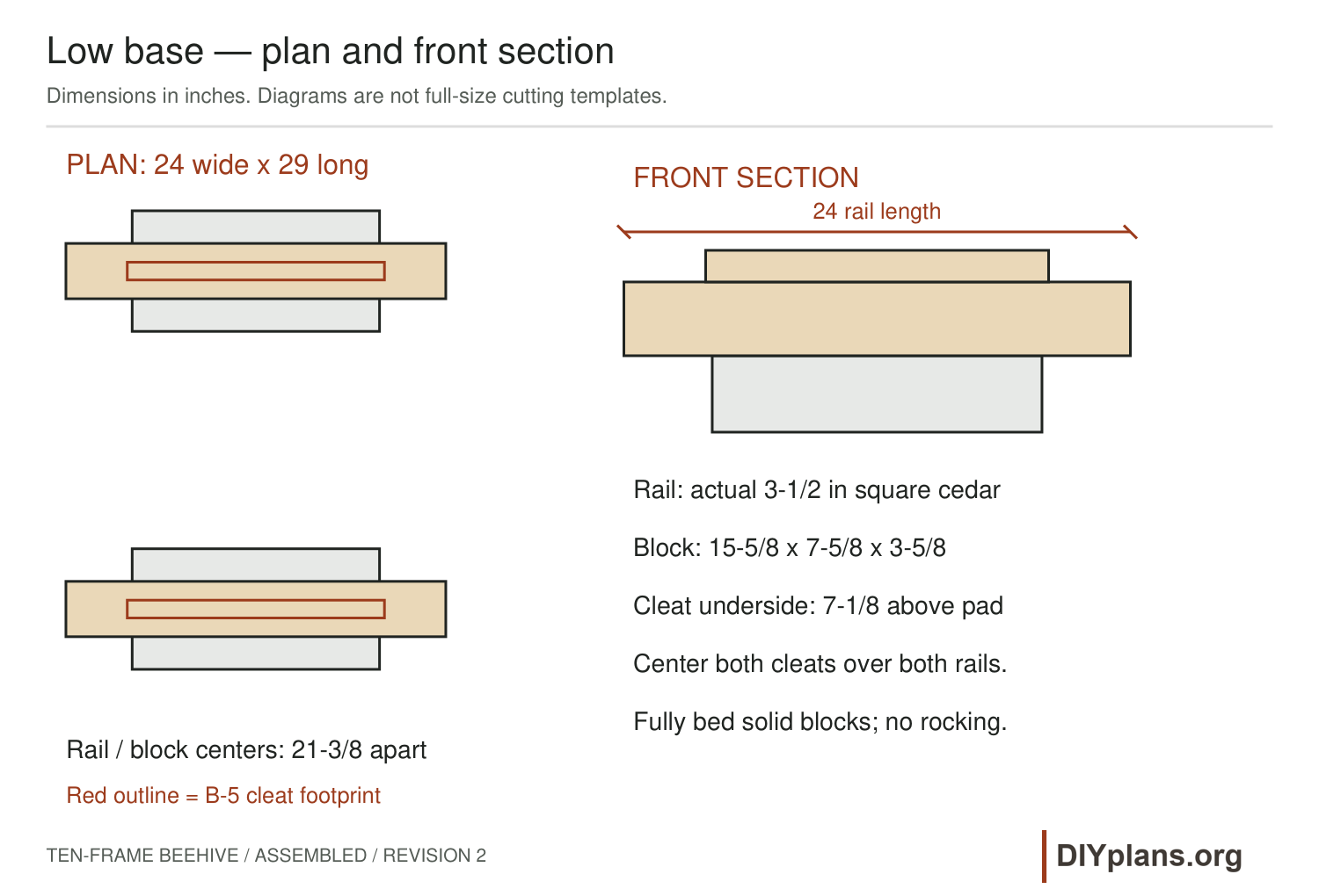
- Choose a sheltered, accessible site on firm, well-drained ground. Prepare two fully compacted, non-rocking bearing pads in a common drainage plane; remove organic material and soft pockets. Use two solid concrete cap blocks, actual 15-5/8 x 7-5/8 x 3-5/8 in, broad faces fully bedded. Do not stack or substitute hollow blocks.
- Place the blocks with their long direction across the hive. Set their centers 21-3/8 in apart front-to-back. Center one 24 in long, actual 3-1/2 in square No. 2 or better Western Red Cedar rail on each block, also across the hive. The rails extend 4-3/16 in beyond each block end.
- Center the two bottom cleats on the rails: cleat centerlines are 9/16 in and 21-15/16 in from the deck front. Across the width, center the 16-1/4 in cleats on the 24 in rails. Both cleats must bear continuously on the rails. The level base raises the bottom cleat undersides 7-1/8 in above the pads.
- Keep the base level across its width. Bed both broad block faces in the same slightly forward-draining plane, with the rear block center about 1/8 in higher over the 21-3/8 in center spacing. Both rails and both cleats must share that pitch for continuous flat bearing. Do not leave the block faces horizontal while pitching the hive, or wedge individual loose corners. Confirm all four wood-to-block and cleat-to-rail interfaces sit flat without rocking.
- Wrap the outdoor hive strap across the width around the lid and bottom board near the middle of its length, clear of the entrance and cap corners. Tighten firmly without distorting the boxes. The strap retains the stack, not the base. This detail has no wind or ground-anchor rating: use a sheltered location and obtain a local anchorage design if exposure demands one. Never sit, stand or climb on the hive.
Check: Blocks are fully bedded, rails and cleats are centered with continuous contact, the entrance drains forward and the strapped stack does not rock.
10 Fit the frames and prepare for occupancy
- Install ten deep frames in the lower box and ten medium frames in the upper box. Keep Hoffman shoulders together and center each set laterally. Check that the top bars bear at both ends and can be removed individually without scraping the walls.
- With matching hanging-ear thicknesses, the gap between deep-frame tops and medium-frame bottoms is 3/8 in. The medium-frame bottoms sit 1/16 to 1/8 in above their box bottom, and frame tops sit 1/4 to 5/16 in below each rim. Under the direct lid, maintain 1/4 to 3/8 in clear top space. Measure real frames; correct a mismatch before occupancy.
- This equipment package is one deep body and one medium super. It does not establish sufficient brood or winter food capacity for every colony or climate. Arrange local beekeeping instruction, protective equipment and a seasonal plan for feeding, pest management, ventilation and additional boxes as needed.
- Adjust or remove the entrance reducer according to colony strength, weather and traffic; a permanent reduced entrance can restrict ventilation. Inspect the weather cap, base, strap, wood decay and screw joints regularly. Remove the strap and lift components separately during service; no carrying handles or whole-hive lifting points are provided.
Check: All 20 actual frames fit and maintain the stated gaps; the local beekeeping and seasonal equipment plan is in place before bees arrive.