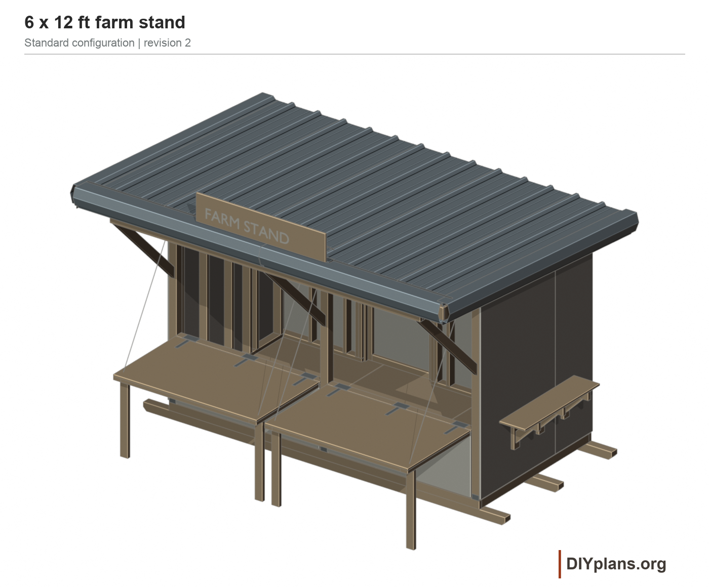
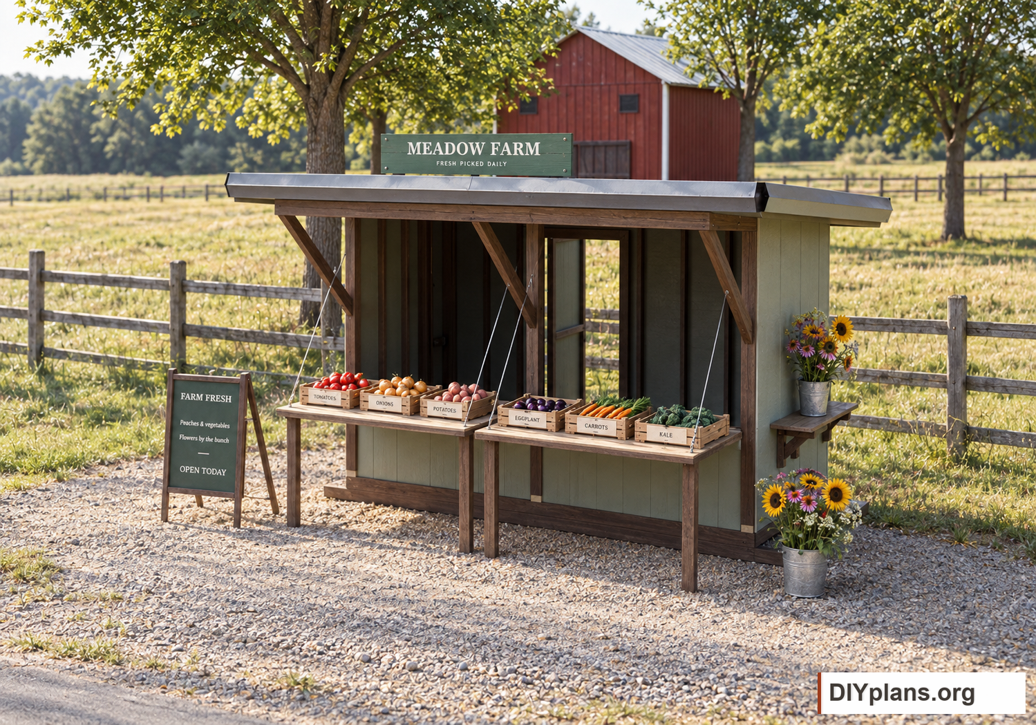
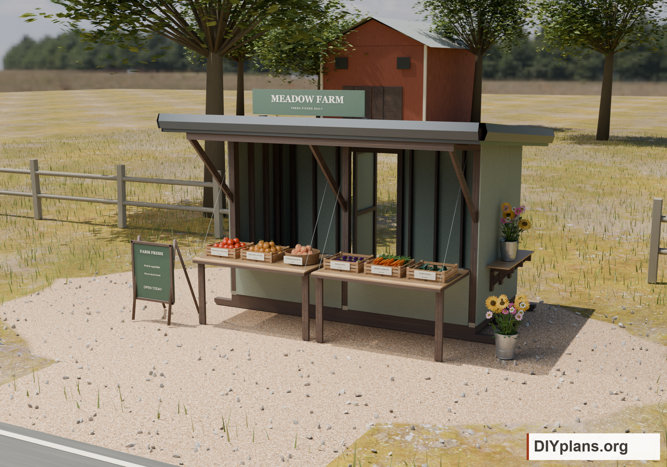

Before you start
- Read the cut list, dimension drawing and the complete folding sequence before cutting. Sort and label the matching parts; reserve hardware-backing pieces before using offcuts.
- Use straight exterior framing lumber, ground-contact-rated 4x4 skids, 3/4 in structural floor plywood, 5/8 in structural exterior roof plywood and 5/8 in structural exterior plywood siding. Match the panel span ratings and fastener compatibility to the selected products.
- Use the front-left corner of the floor framing as the layout datum. Across the stand is left to right; depth runs from the counter side to the rear door. Measure stated ground heights from the common level bearing plane under the skids and counter feet.
- Transfer the floor and roof panel cuts directly from the cut list. Those cuts already provide 1/8 in supported butt joints. Keep the 48 in layout marks on the framing; do not remove another 1/8 in from every panel.
- Select the counter tee hinges, folding leg brackets, door hinges, chain fittings and sign stays before drilling. Lay them on the parts and check every mounting hole lands on a rail, plate, stud or full-depth backing piece.
- Provide a temporary brace for every free-standing wall and a stable, clamped prop for each counter during fitting. Use helpers for long beams and sheet goods. Keep fingers out of hinge knuckles and under the counter edges.
- Arrange a stable work platform and fall protection for roof work. Keep feet and material stacks off the canopy overhang. Carry each long metal sheet with a helper; stop handling panels when wind makes them difficult to control. Wear cut-resistant gloves.
- Order the PBR roof as one compatible system for this 1:12 slope over 5/8 in structural plywood: full-length sheets, underlayment, low-eave and high-side trim, rake trim, closures, tape and flashed sign mounts. Confirm the plywood fastener type and row spacing for the site exposure with the roof supplier before drilling.
- Order five 122 in long, 36 in net-cover sheets. Four remain full width; form the last to 25 1/2 in finished cover plus a 1 in upturned rake leg. Check the supplied overlap rib and bend detail before cutting that edge. Do not introduce panel end laps.
- Dry-fit the sign hinges, locking stays, raised feet and resting pads against a sample of the roof profile and the high-side trim. Keep moving hardware clear of the ribs. Roof screws attach the cladding; sign bolts pass into its framing and backing.
- Install this stand on a firm, drained, level base that supports all three skids continuously. Keep the four counter-foot pads at that same level. Raising the skids raises the counter; move the pads with them and check leg fit.
- Select the site anchoring system before raising the walls. For soil, use a manufactured ground-anchor system selected for the actual soil and wind exposure. For a slab, choose anchors for its verified thickness, edge distances and condition. Record the anchor model, quantity, locations and embedment in the installation notes supplied with the stand.
- Connect the selected anchors to solid skid or floor-frame brackets at the four corners, with additional points if its schedule requires them. Maintain the connection path through floor, posts, walls, rafters and roof edges. A loose block or the stand's weight is not an anchor.
- Use the stand for attended produce display. Spread small containers over the counter rails and supported shelf brackets. Keep people, seated customers, stacked bulk bins and climbing loads off the counter, shelf and roof; no allowable capacity is assigned by this plan.
- Close and latch the counters, rear door and sign before strong winds or when leaving the stand unattended. Do not operate a counter when gusts make the panel difficult to control. Secure closures do not replace the site anchors.
- Check local wind, snow and frost requirements when choosing the site, framing grade, roof fastening and anchors. This drawing assigns no wind speed or snow-load rating. Keep the stand clear of falling or drifting snow from nearby buildings. Keep it closed during snow accumulation and arrange removal from the ground without scratching or denting the roof. Keep the rear door approach outside falling snow and ice from the low eave.
- Confirm the local requirements for a roadside sales stand, setbacks, traffic visibility, drainage and customer access. The 7 3/4 in rear floor rise is not a finished public-access entrance; provide a separate step or accessible approach where required, without obstructing the door or skid ends.
- Use a separately planned lifting and transport method if relocating the stand. Unload it, latch the moving parts and release anchors in a controlled sequence. The skids and hardware are not towing or lifting points.
- Keep this an unheated, open-front stand. Insulation, plumbing, electrical equipment, refrigeration and food-preparation facilities need their own installation details.
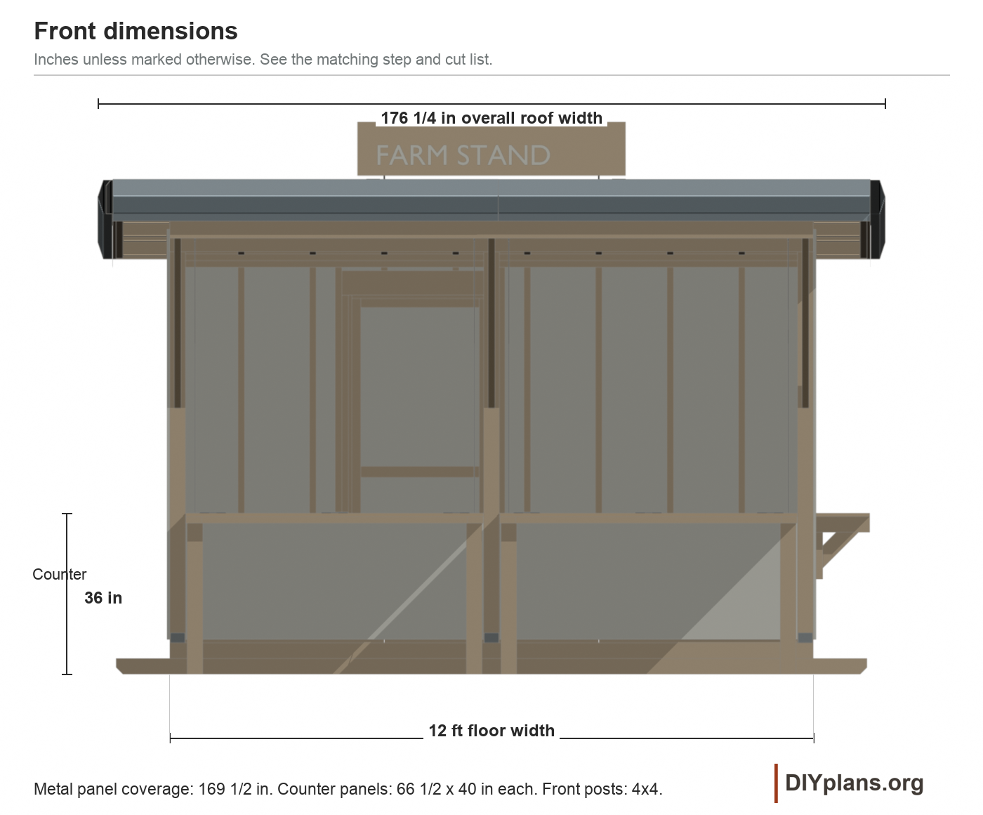
Dimensions and opening sizes
- Floor widthOutside floor framing.
- 144 in
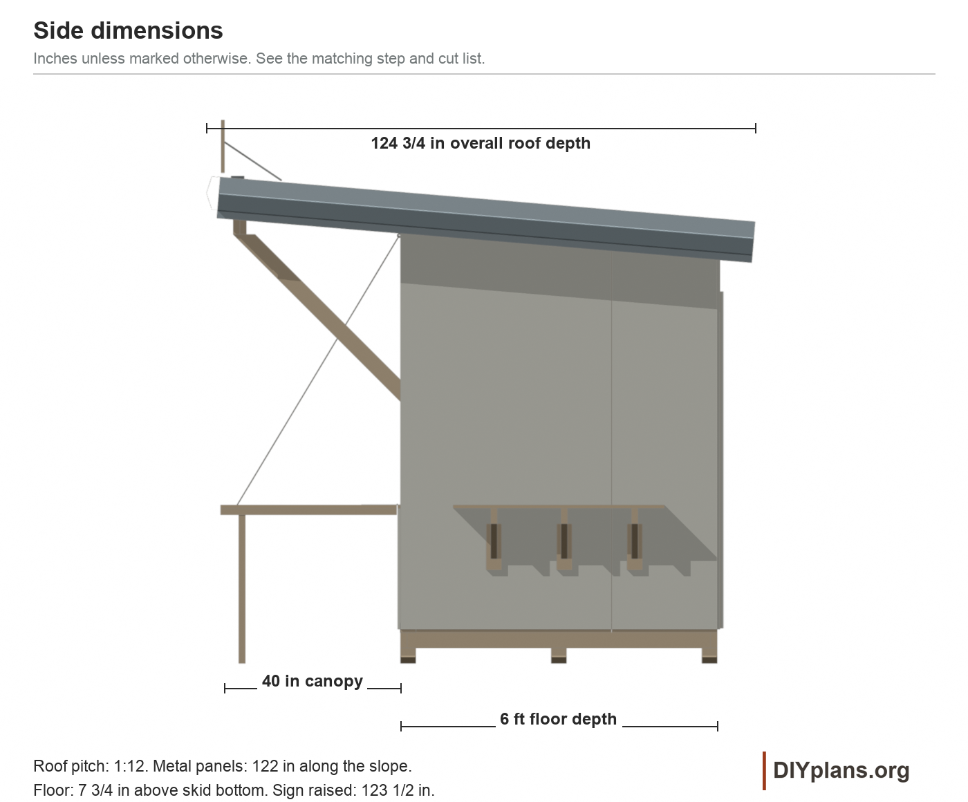
- Floor depthFront to rear floor framing.
- 72 in
- Counter heightAbove the level bearing plane beneath skids and counter feet.
- 36 in
- Each counter widthTwo independent panels.
- 66 1/2 in
- Counter depthEach panel projects forward.
- 40 in
- Skid lengthThree skids, each extending 12 in beyond the floor ends.
- 168 in
- Height with sign raisedAbove the skid bearing plane.
- 123 1/2 in
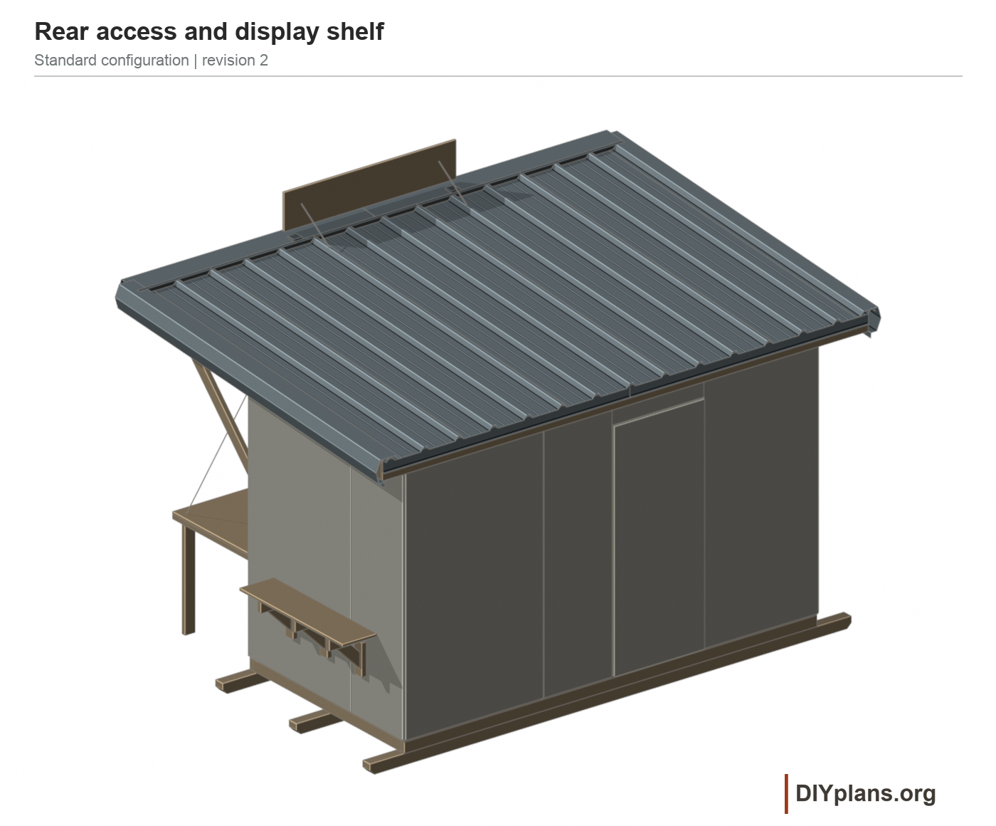
- Display shelf length12 in deep, 36 in high.
- 48 in
- Roof depth over trimHorizontal front-to-rear footprint, including trim; use for site clearances.
- 124 3/4 in
- Roof width over rake trimUse this outside width for site clearances.
- 176 1/4 in
- Metal roof cover widthFour 36 in cover widths and one 25 1/2 in finishing width.
- 169 1/2 in
- Roof sheet lengthOne continuous sheet down the slope; no panel end laps.
- 122 in
- Roof rise per 12 in runHigh at the counters; falls toward the rear door.
- 1 in
Shopping & cut lists
Get the shopping and cut lists
Includes all available CAD files, shopping lists and cut lists for every configuration of this plan. One payment, $19 USD.
Get the plan package · $19Secure checkout with Stripe. Your account is created after payment.
Already purchased? Sign in to access your plans.
Tools & equipment
- Tape measure, framing square, combination square, chalk line and pencil
- 4 ft level or laser level, plumb bob and straightedge
- Circular saw with guide, miter saw and handsaw or jigsaw for rafter seats
- Drill/driver, matching driver bits, pilot bits, countersink and bolt-hole bits
- Hammer or depth-controlled framing nailer suitable for the specified nails
- Socket set, spanners and clamps for through-bolted hardware
- Sawhorses, temporary wall braces, clamped counter props and helpers
- Ladders or work platform, with a roof-access arrangement appropriate to the site
- Utility knife, scissors, clean broom, sealant gun and the underlayment maker's roller or cap-fastening tools
- Eye and hearing protection, dust protection for wood cutting, cut-resistant gloves and nonslip footwear
- Metal snips or nibbler, deburring tool and a sheet-metal brake or supplier bending service for the final rake leg
- Clutch-controlled screw gun with correctly sized roofing sockets; drill bits for the selected Type AB roof screws and sign bolts
- Soft brush or magnetic swarf pickup, padded panel supports and non-staining layout markers
BEFORE YOU BUILD
Use this work at your own risk
No person or organization makes any guarantee or warranty, express or implied, regarding this design, its documentation, digital files, or website views. They are not professional services and do not create an architect-client or other professional-client relationship. No promise is made about accuracy, completeness, reliability, code compliance, or fitness for your project.
Buildings and building projects are complex, and many things can go wrong. You are responsible for checking dimensions and site conditions, choosing suitable materials and methods, obtaining permits, following codes and manufacturer instructions, and getting qualified professional help when needed. To the fullest extent permitted by law, DIYPlans.org disclaims liability for damages resulting from use of this work. Read the FAQ about your responsibilities.
Instructions
01 Mark the site
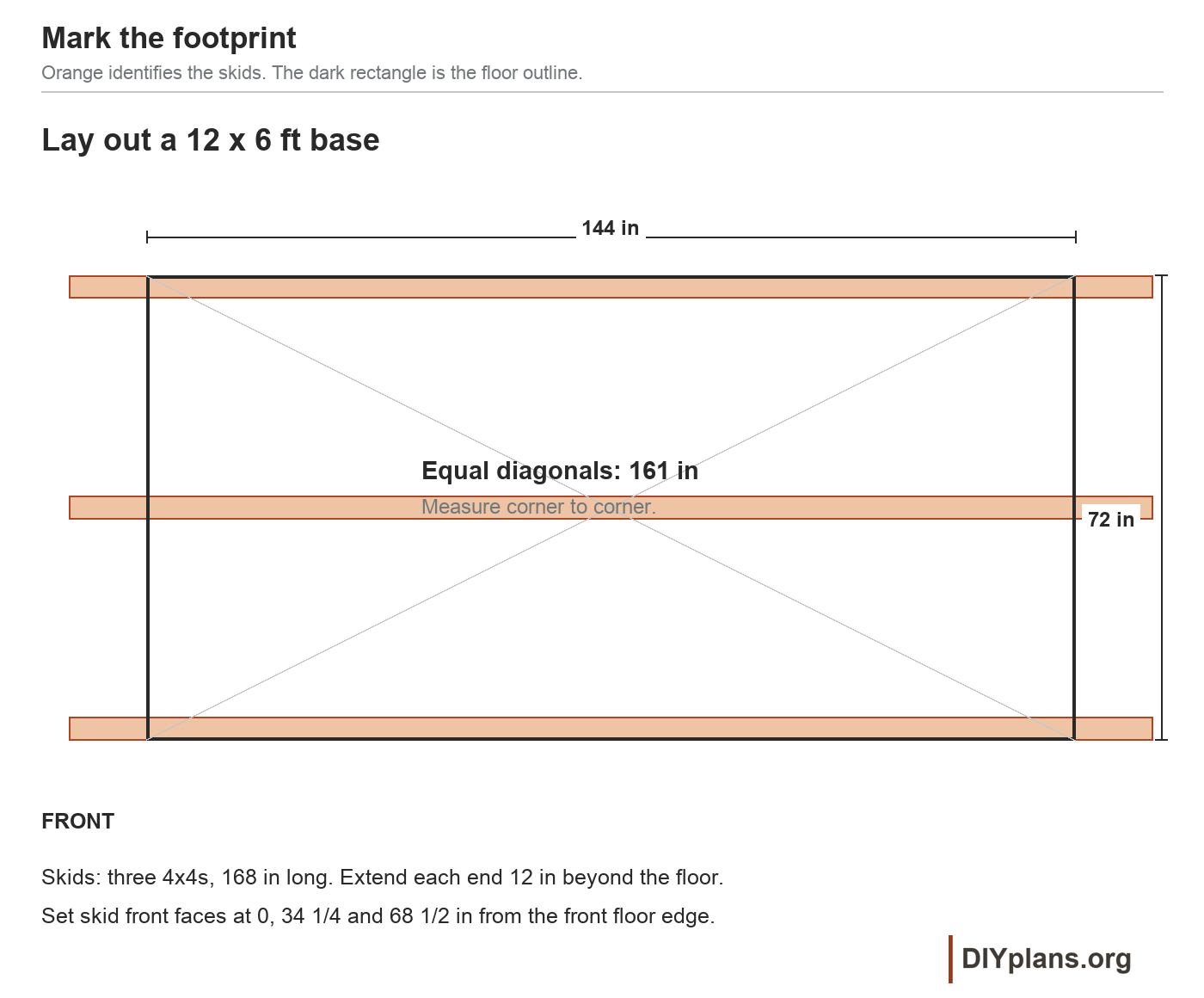
- Mark a 144 x 72 in rectangle at the outside of the floor framing. Match both diagonals to about 161 in, then check the exact corners with a square.
- Allow 12 in of skid beyond each end of the floor, about 41 in of open counter in front, the roof overhangs and a clear rear door swing.
- Prepare the level, drained bearing strips and select the site anchors described under installation assumptions. Keep public paths outside the anchor ties and counter movement area.
Check: The floor rectangle is square, and the roof, counter, door and anchor locations fit the site.
02 Lay the skids
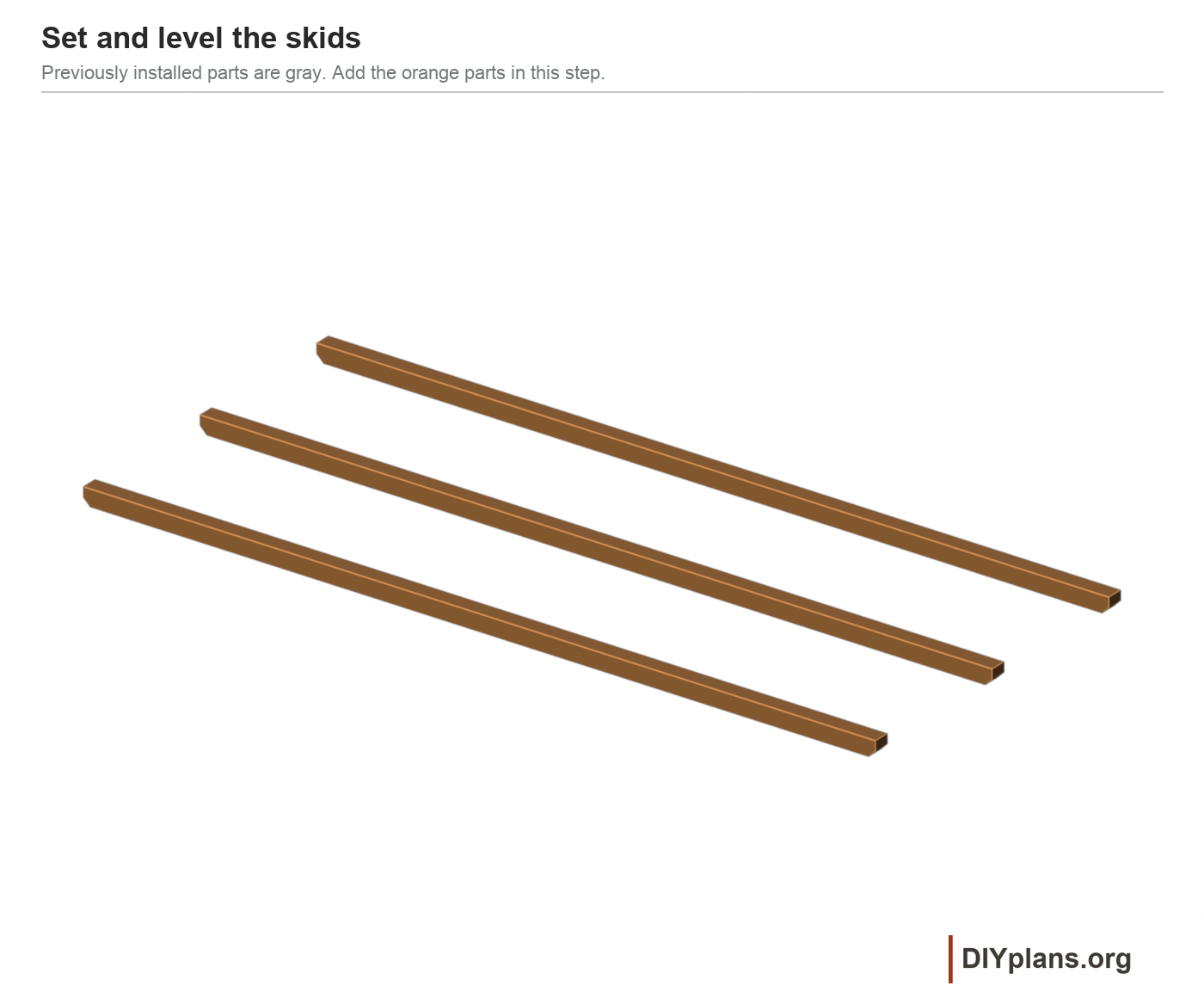
- Cut three ground-contact 4x4 skids to 168 in. Clip each lower end corner 1 1/2 in at 45 degrees and treat the fresh cuts.
- Run the skids left to right. Put their front edges at 0, 34 1/4 and 68 1/2 in from the front floor line; their centerlines are 1 3/4, 36 and 70 1/4 in.
- Project each skid 12 in past both floor ends. Pack the continuous bearing strips with stable, non-rotting material and check all skid tops in one level plane.
- Install the anchor brackets that become inaccessible under the floor, using the selected site system.
Check: All three skids bear firmly and have level tops.
03 Mark the floor frame
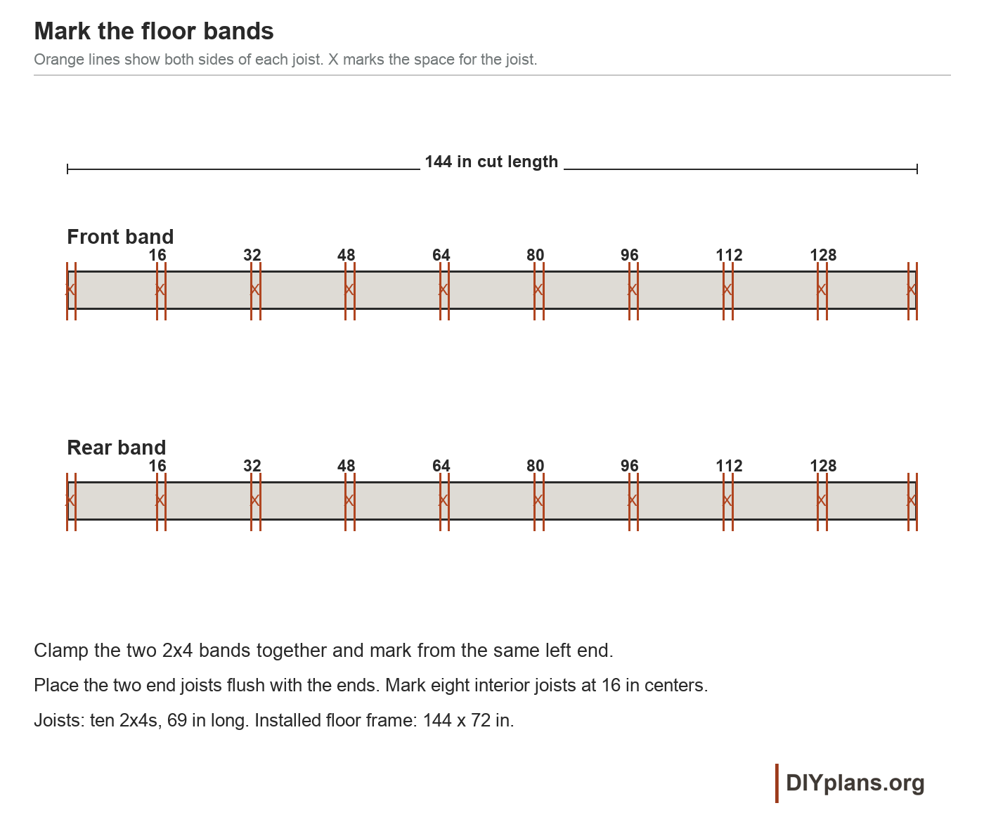
- Cut two 2x4 bands to 144 in and ten 2x4 joists to 69 in. Stand the members on edge.
- Clamp the two bands together with their left ends flush. Mark intermediate joist centerlines at 16, 32, 48, 64, 80, 96, 112 and 128 in from that end.
- Mark the two end joists flush with the outside ends. Transfer the 48 in depth seam line from the front outside edge and label the floor-blocking pieces.
Check: Both bands have matching joist marks; the seam blocking follows the floor-panel layout.
04 Assemble the floor frame
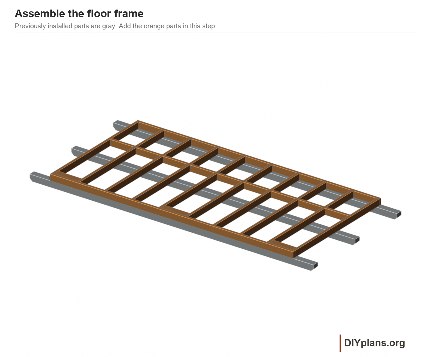
- Fit the 69 in joists between the two bands to make a 144 x 72 in frame. Fasten each joist end with two 3 in framing screws.
- Fit nine 2x4 seam blocks with their centers 48 in behind the front outside edge. Use the cut-list lengths, including the shorter end bays; fasten each end with two 3 in framing screws.
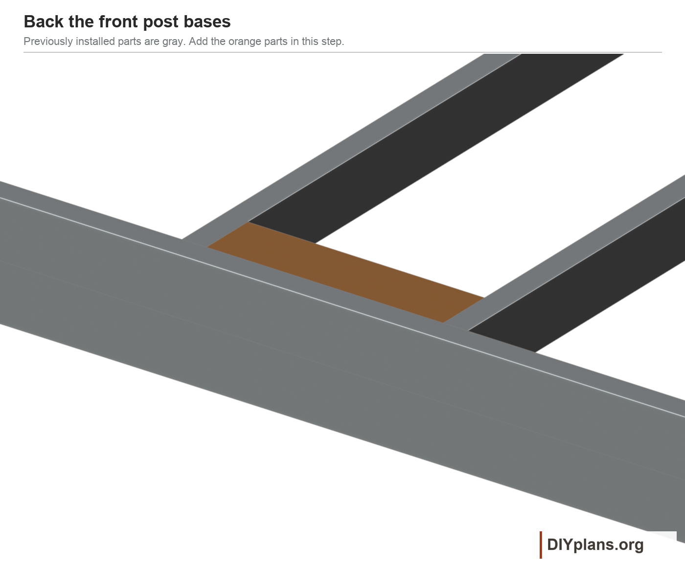
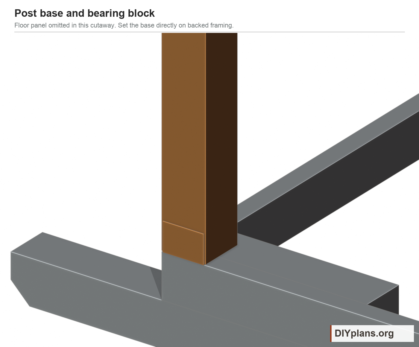
- Fit three 4x4 post-backing blocks behind the front band, with their tops flush with the floor frame. Cut the left and right blocks to 13 3/4 in and the center block to 14 1/2 in. Their left edges are 1 1/2, 64 3/4 and 128 3/4 in from the left floor edge; each runs from 1 1/2 to 5 in behind the front framing line. Fasten them into the adjoining joists and front band before fitting the bases.
- Dry-fit the three Simpson BC40 post bases directly on the backed floor framing at the front-post locations. Orient their upright ears toward the front and rear. Use the complete specified connector fastener pattern and leave the post sockets accessible.
- Square the frame on the skids. Drive the thirty 6 in floor-to-skid screws before covering the frame.
- Thirty 6 in exterior timber screws. Drive ten through each long floor band into its outer skid and ten through joists into the center skid. On the long bands use stations 4, 20, 36, 52, 68, 84, 100, 116, 132 and 140 in from the left end. Keep heads below the plywood bearing plane.
Check: The frame is square and fixed to every skid; all panel edges and post bases have solid backing.
05 Fasten the floor panels
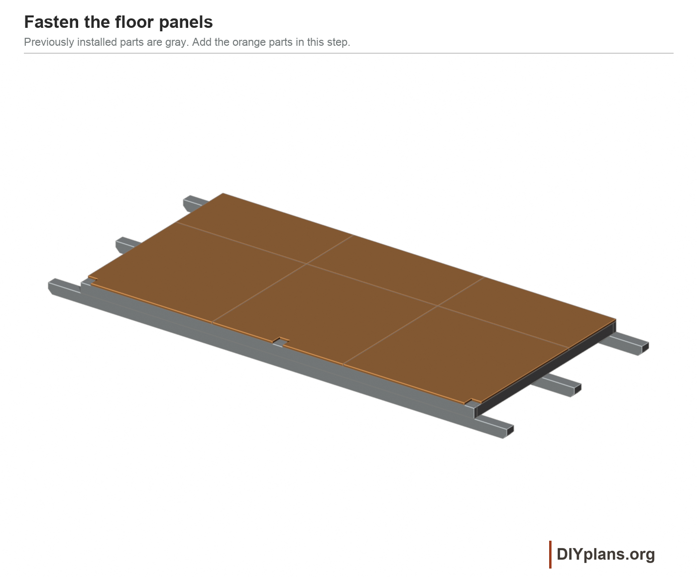
- Lay the front row of 3/4 in plywood left to right: 47 15/16 x 47 15/16 in, 47 7/8 x 47 15/16 in, and 47 15/16 x 47 15/16 in. Keep the panel strength axis across the joists.
- Lay the rear row left to right: 47 15/16 x 23 15/16 in, 47 7/8 x 23 15/16 in, and 47 15/16 x 23 15/16 in. Put the cut long edges over the seam blocking.
- Mark and notch the front panels around the fitted BC40 bases, leaving the connector sockets and fasteners accessible. Keep each cut edge supported and seal it before fastening the panel.
- Maintain the drawn 1/8 in butt joints and the panel maker's tongue-and-groove fit. Keep the outside edges flush with the floor frame.
- Nail at 6 in along supported edges and 12 in on intermediate framing. Mark the framing lines on top for later wall and hardware screws.
Check: The floor surface is 7 3/4 in above the skid bearing plane and has no unsupported panel edge.
06 Set the front posts
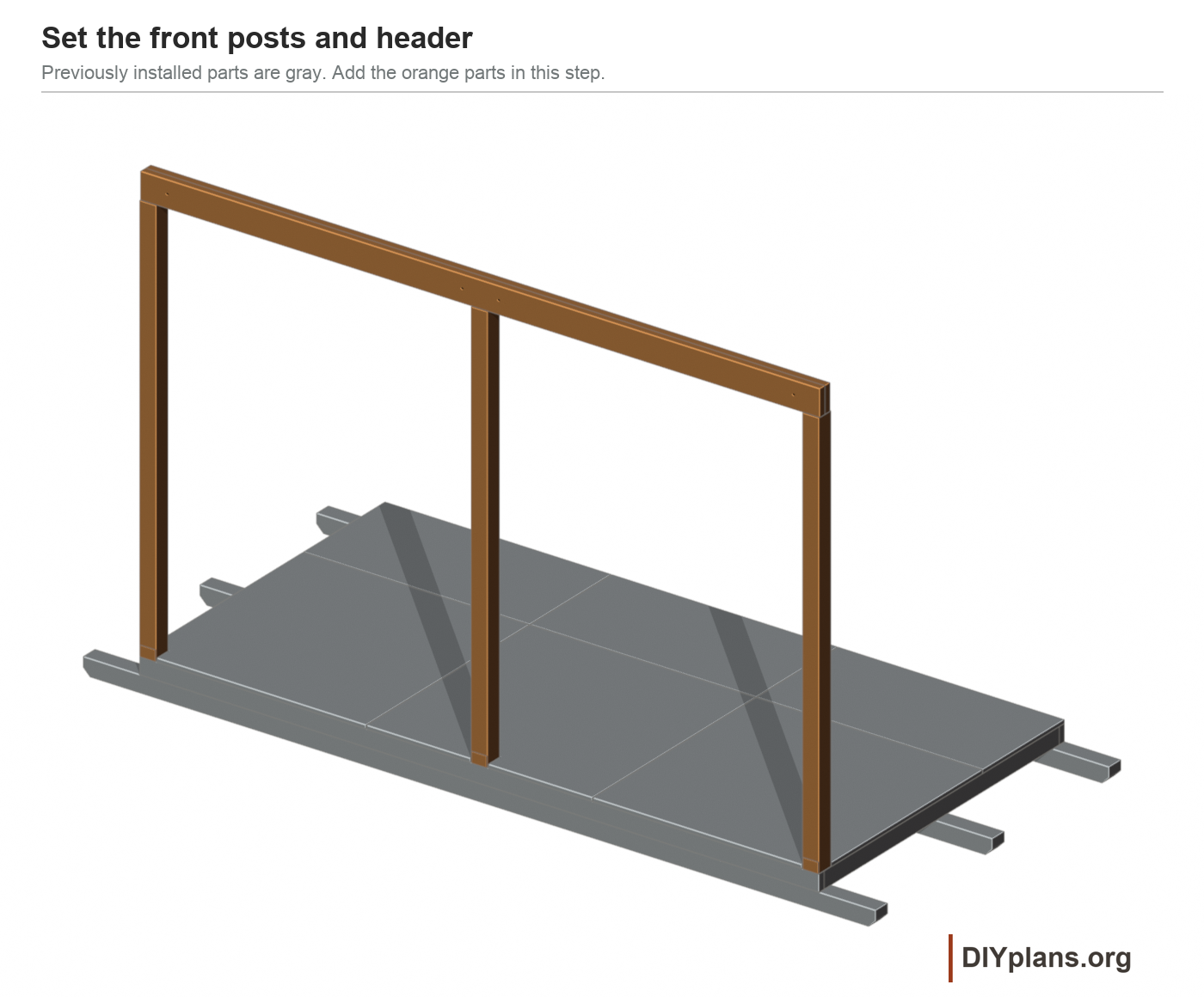
- Fit the three 4x4 posts into the installed BC40 bases. Put their left faces at 0, 70 1/4 and 140 1/2 in from the left floor edge, with their front faces on the front framing line.
- Measure the finished base seat height before cutting the posts. Cut each post to put its top at 94 1/2 in above the skid bearing plane. A base plate seated at 7 in with a 1/16 in thickness gives a reference post cut of 87 7/16 in; dry-fit the actual hardware and measure for the final cut.
- Plumb and temporarily brace every post in both directions. Fasten each post in its base using the BC40 installation schedule.
- Clamp two 144 in 2x6 header plies together and fasten them. Seat the header on the posts, with its top 100 in above the skid bearing plane.
- 3 in structural framing screws, two rows at 16 in spacing for the two-ply front and canopy beams; about 20 per beam. Stagger rows and start away from board ends to meet the screw schedule. Clamp plies together. At wall intersections fasten contacting framing at 16 in maximum spacing. Use the specified caps and BC40 bases at front posts.
- Install all three post caps with their complete fastener packs. Keep temporary braces until the walls and plywood siding are fixed.
Check: The two counter bays are each 66 3/4 in clear, and the header is level on all three posts.
07 Frame the back wall
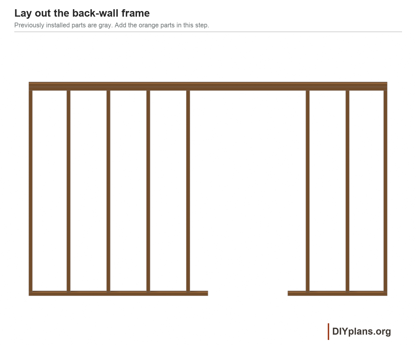
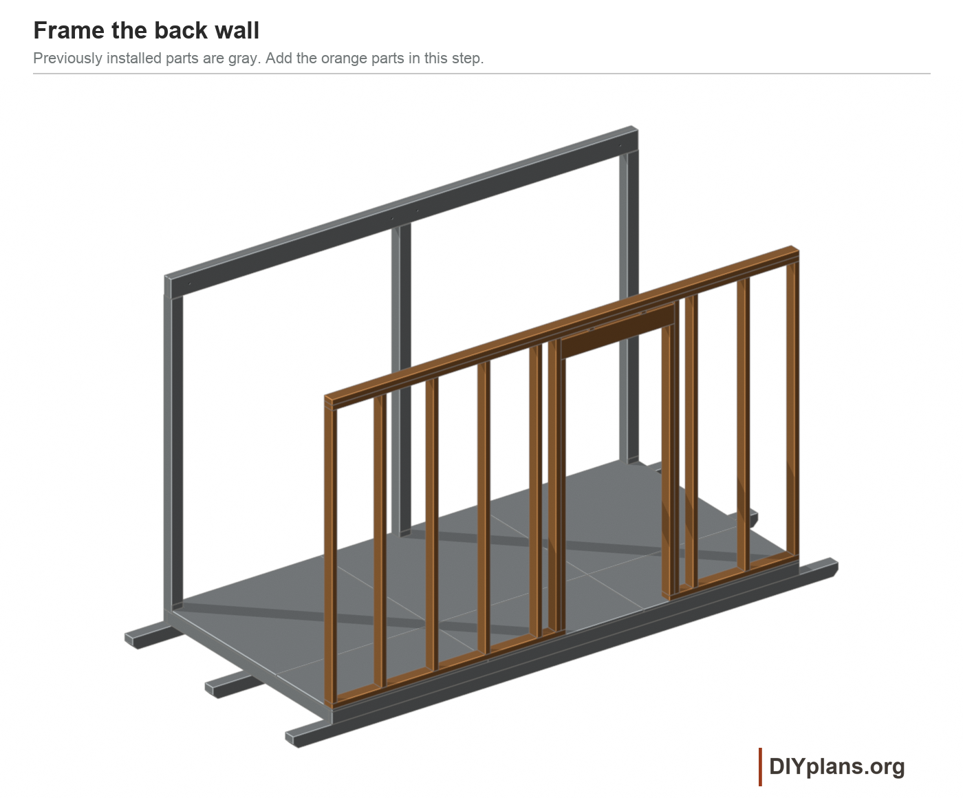
- Lay out the rear wall on the floor. Use 40 and 72 in bottom-plate pieces with a 32 in door gap between them, from 40 to 72 in measured from the left floor edge.
- Cut the eight ordinary back studs and two door king studs to 81 3/4 in. Place the ordinary studs to the wall-layout marks; keep the door framing separate for the next step.
- Fasten ordinary studs between the bottom plates and the first 144 in top plate. Fit the second 144 in top plate; the finished wall top is 94 in above the skid bearing plane.
- Use two 3 in framing screws per ordinary stud end. Keep the frame flat and square while adding the door members.
Check: The rear-wall layout preserves the full 32 in door opening.
Play movementStop movement

08 Frame the door opening
- Place a 75 1/2 in 2x4 jack stud inside each full-height king stud. Set the inside jamb faces 40 and 72 in from the left floor edge.
- Make the door header from two 35 in 2x6 plies and the 35 x 5 1/2 in plywood spacer. Seat it directly on the jack studs, with its underside 77 in above the finished floor.
- Fit the two 3/4 in header packers between the header and lower top plate. Fasten the king-and-jack pairs at 16 in maximum spacing.
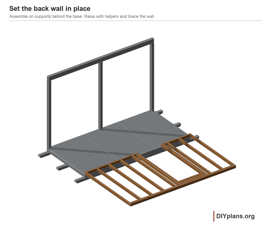
- Assemble the back wall on level supports behind the base, with its lower edge at floor height. Clear the full wall swing, raise it with helpers, fasten the bottom plates into the floor frame, and brace it plumb.
Check: The opening measures 32 x 77 in from finished floor to header underside.
09 Fit the side walls
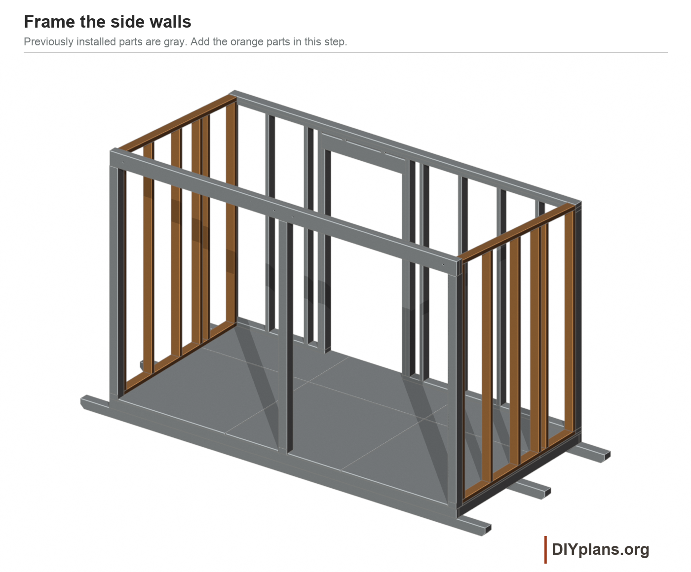
- Cut the two 2x4 side bottom plates to 64 15/16 in. Start each plate 3 9/16 in behind the front floor line, leaving clearance for the post-base wing. Keep the top-plate and stud positions on their original wall-layout marks.
- Use the sloped top plates and five individually labeled studs per side from the cut list. Bevel the stud tops and plate ends 4.764 degrees; keep each stud's long point toward the front.
- Place the stud front faces at 3 1/2, 19 1/2, 35 1/2, 51 1/2 and 67 in from the front floor line. Check the sloping plate against the matching rafter profile.
- Fasten the frames, then fix their bottom plates into the side floor joists and their ends into the front posts and rear wall. Brace both walls plumb.
Check: Both side walls follow the roof fall toward the rear and meet the adjoining frames without forcing.
10 Build the counter walls
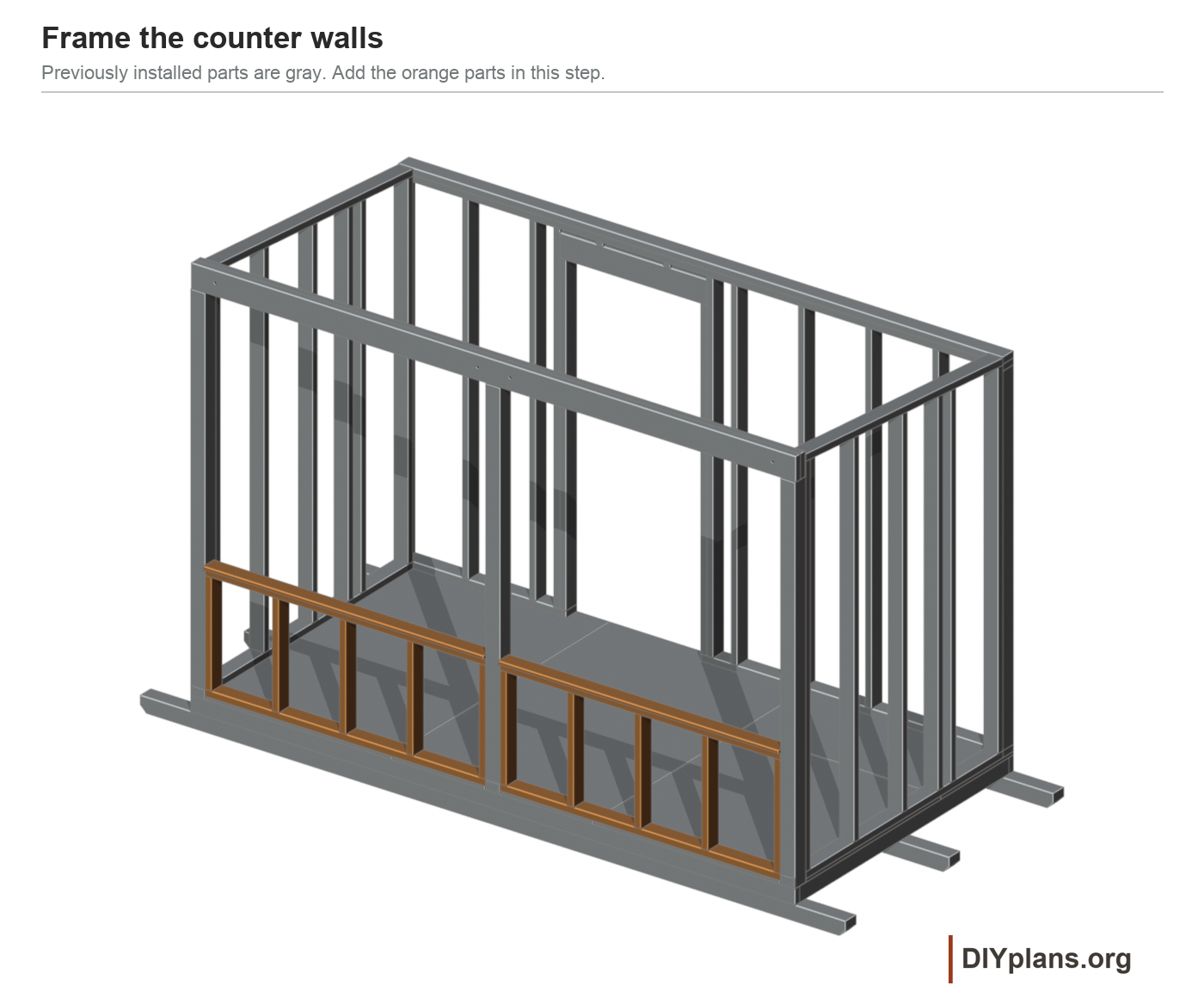
- Build two low frames with 66 3/4 in 2x4 top and bottom plates and five 24 1/2 in studs each. Place the end studs flush and the remaining stud front edges 16, 32 and 48 in from the frame's left end.
- Fit the frames between the front posts. Fix their bottoms into the front floor band and their ends into the posts; the top of each 2x4 plate is 35 1/4 in above the skid bearing plane.
- Fit a 66 3/4 in 1x4 hinge cap over each top plate. Project its front edge 5/8 in beyond the front framing face and keep its upper surface at 36 in.
- Screw the caps into the plates in two staggered rows. Keep future hinge holes clear of these screws.
Check: The hinge caps are level, straight and securely backed by the low-wall top plates.
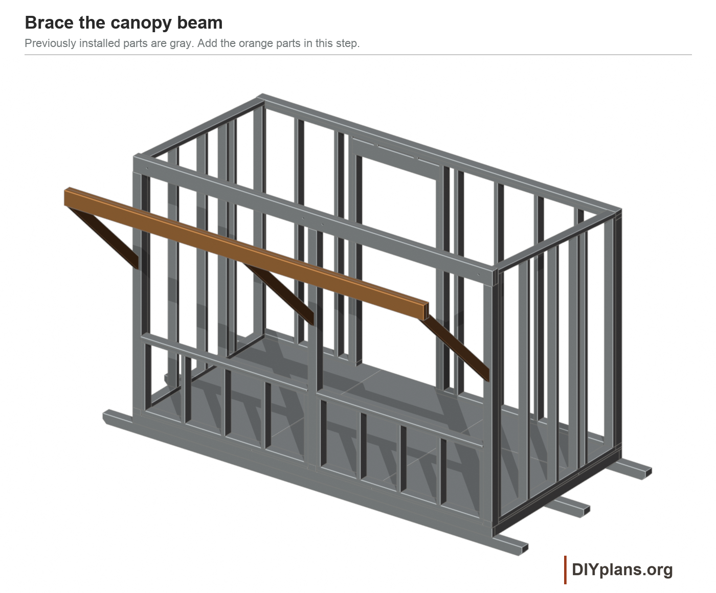
11 Brace the canopy beam
- Make the canopy beam from two 144 in 2x6 plies. Fasten the plies as for the front header.
- Cut the three 2x4 braces from the full-size layout. Each long edge has 38 in horizontal and vertical legs, about 53 3/4 in between its long points, with 45 degree ends.
- Support the canopy beam on temporary props, with its front face 38 in ahead of the front framing line and its top 103 in above the skid bearing plane.
- Fit one brace against each front post. Seat the upper end tightly under the beam and fasten both ends. Leave the props in place until the rafters and deck tie the canopy to the stand.
- Two 5 in exterior structural timber screws per end; 12 total. Clamp each fitted brace with full bearing against its post and canopy beam. Predrill the selected screw path from the brace face so the threads enter solid side grain of the receiving member. Maintain the screw maker's spacing and end distances; the fasteners retain the bearing joint.
Check: All three braces have full bearing; the beam is level and remains safely propped.
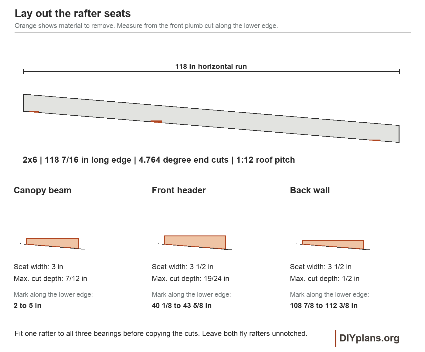
12 Mark one rafter
- Use a 2x6 blank with a 118 7/16 in long edge, approximately 118 7/16 in. Mark 4.764 degree plumb ends and a 118 in horizontal run. Label the front plumb face before marking any seat.
- Mark the canopy seat from 2 to 5 in horizontally behind the front plumb face. Make it 3 in wide, with a maximum depth of 7/12 in. The corresponding positions along the sloping bottom edge are 2 and 5 in.
- Mark the front-wall seat from 40 to 43 1/2 in horizontally behind the same face. Make it 3 1/2 in wide, with a maximum depth of 19/24 in. Its sloping-edge marks are 40 1/8 and 43 5/8 in.
- Mark the rear-wall seat from 108 1/2 to 112 in horizontally behind the same face. Make it 3 1/2 in wide, with a maximum depth of 1/2 in. Its sloping-edge marks are 108 7/8 and 112 3/8 in.
- Cut each seat so it is horizontal when the rafter is installed. Keep the saw kerfs inside the marked corners and finish them with a handsaw; the stated maximum depth is measured vertically in the installed roof.
- Dry-fit this first rafter on all three bearings, with their tops at 103, 100 and 94 in above the skid bearing plane. Check full contact before copying the seats to the other nine bearing rafters.
- Cut the two fly rafters to the matching end profile with no bearing seats.
Check: The trial rafter bears on all three supports without rocking or a deeper field-cut seat.
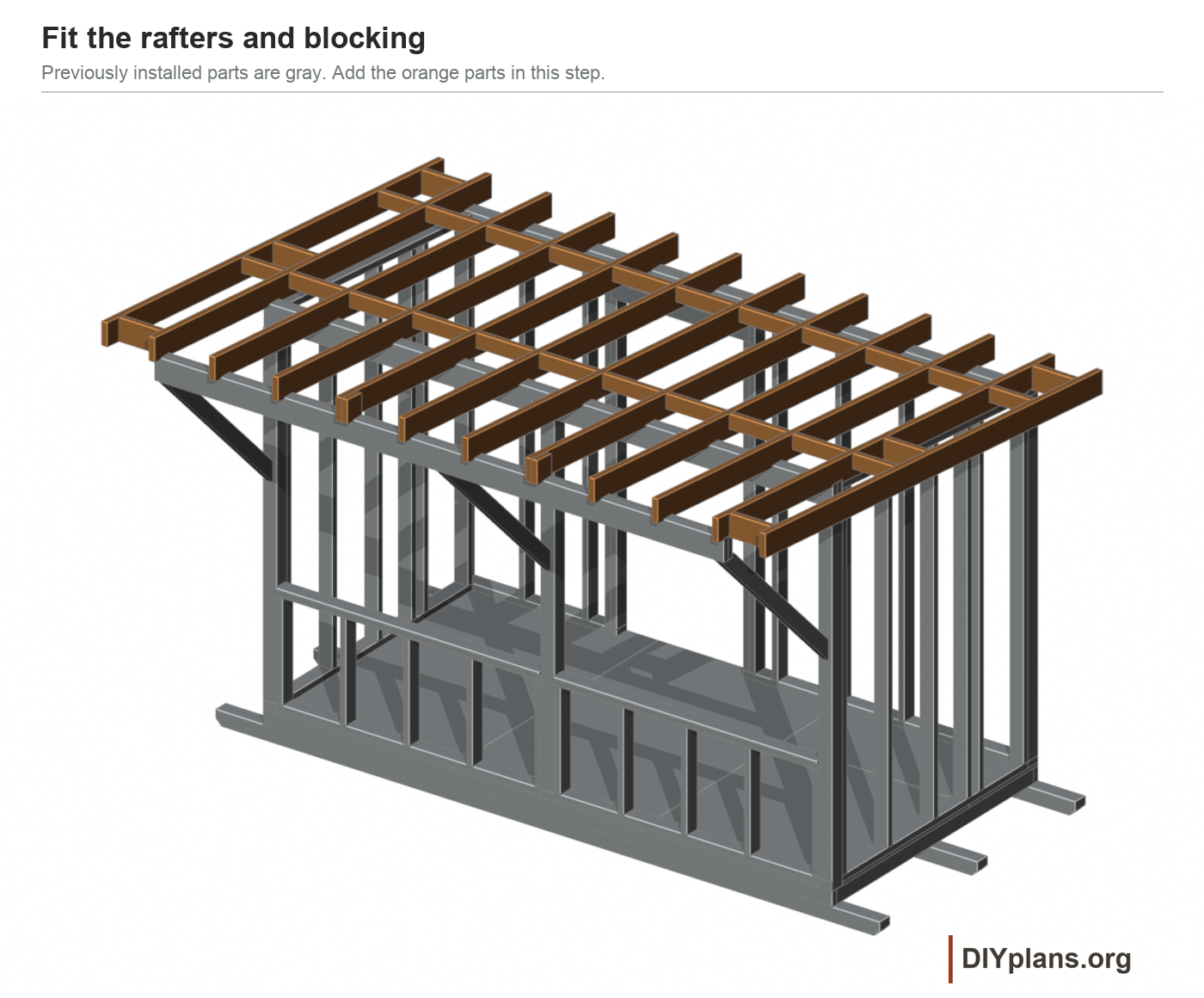
13 Fit the roof framing
- Place the ten bearing rafters over the floor-joist layout, with the two outer bearing rafters flush with the floor ends. Fit a tie at all three bearings of each rafter.
- Thirty H2.5AZ ties with five 1/8 x 2 1/2 in connector nails into each member per tie. Install one tie at each bearing of each of ten rafters. Orient the tie so all required holes land in the rafter and support. Use connector nails, not roofing nails or ordinary deck screws.
- Fit the two fly rafters at the roof edges, 12 in outside the floor framing. Connect each to the adjoining bearing rafter with three 10 1/2 in 2x6 lookouts at the illustrated positions.
- Install the two rows of 2x4 roof seam blocks, centered 48 and 96 in along the slope from the front rafter cut. Use each labeled bay length; bevel their upper edges to follow the roof.
- Fasten lookouts and seam blocks with two 3 in screws per end. Keep all tops flush with the rafters.
- Fit the two 2x6 sign-hinge backing blocks from the cut list beside the 48 and 96 in rafter lines. Keep their canopy bearing seats fully supported. Mark the stay positions on those rafter centers, 27 in ahead of the front wall. Dry-fit the raised mount assemblies with a sample PBR sheet, then mark their through-bolt paths and backing washers while the framing is exposed.
Check: All twelve rafters are fixed, and every deck seam and sign mount has backing.
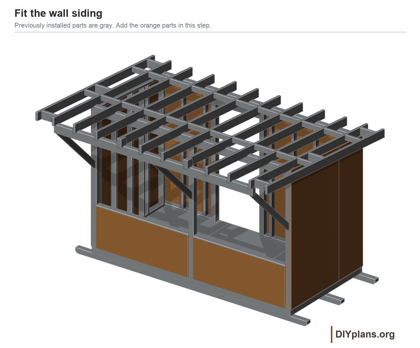
14 Close the walls
- Fit a full-height 2x4 seam stud in each side wall, with its front face 47 1/4 in behind the front floor line so it supports the seam at 48 in. Cut its sloping top from the wall cut list and fasten it to both plates. Back any other panel edge that misses framing.
- Wrap the rear, side and low front walls with the weather barrier. Lap upper courses over lower ones and flash the rear door opening to drain outward.
- Cut and fit the 5/8 in plywood siding to the cut list. Scribe the side tops to the roof line. Finish the back siding at 93 3/8 in above the skid bearing plane, clear of the rafter tails.
- Use the panel maker's edge-joint detail and 1/8 in butt gaps where required. Seal all cut edges before nailing.
- 1/8 x 2 1/2 in galvanized ring-shank nails, 6 in along supported panel edges and 12 in on intermediate framing. Keep nails 3/8 in from panel edges unless the panel maker specifies more. Center both edge rows on their backing. Set heads flush without breaking the face veneer. Add backing at every unsupported cut edge. Use closer spacing where the selected panel or local schedule requires it.
- Recheck wall plumb and fasten all plywood edges into solid framing before removing the wall braces.
Check: Siding edges are supported and sealed, the back panels clear the tails, and the door opening remains square.
15 Lay the roof deck
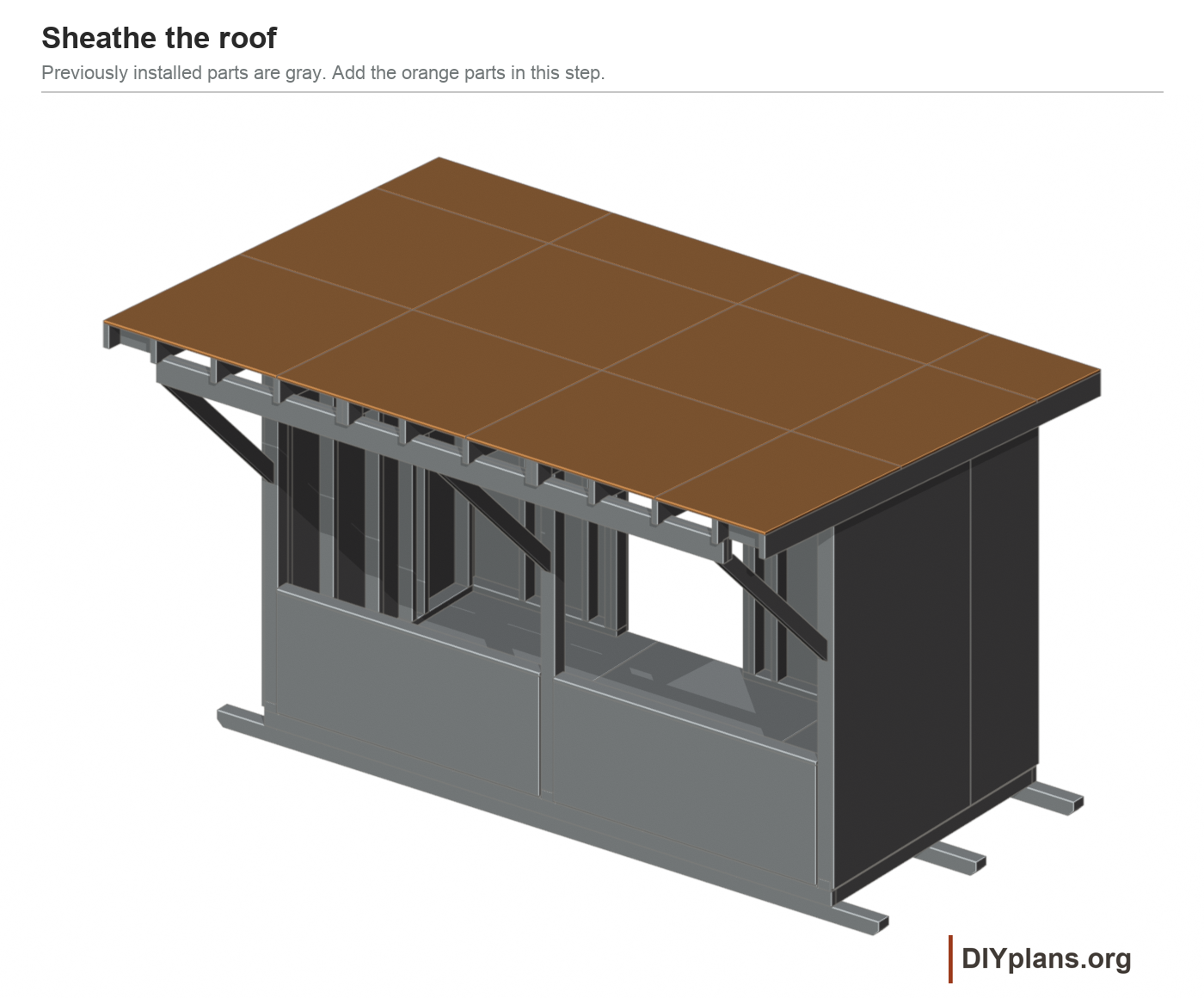
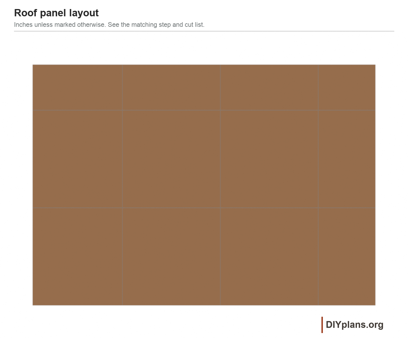
- Lay the twelve 5/8 in roof panels in their labeled rows, with the panel strength axis across the rafters. Start at the front roof edge.
- Use panel widths of 43 15/16, 47 7/8, 47 7/8 and 27 15/16 in from left to right. The first row is 47 15/16 in deep along the slope and the second is 47 7/8 in deep.
- Cut the final row 22 3/8 in deep along the slope. Scribe the back edge to the rafter tails before making the final cut.
- Keep the built-in 1/8 in joints centered on rafters and blocking. Nail every panel, with heads flush and no sharp points or splinters on the roof face.
- 1/8 x 2 1/2 in galvanized ring-shank nails, 6 in along supported panel edges and 12 in on intermediate framing. Keep nails 3/8 in from panel edges unless the panel maker specifies more. Center both edge rows on their backing. Set heads flush without breaking the face veneer. Add backing at every unsupported cut edge. Use closer spacing where the selected panel or local schedule requires it.
- Check the deck with a straightedge and sweep it clean. Confirm the sign bolt paths and photograph the backing positions before covering them. Remove the canopy props only after the framing, roof ties and deck are complete.
Check: The roof is a smooth, fully supported plane with a continuous fall to the rear.
16 Prepare the roof edges
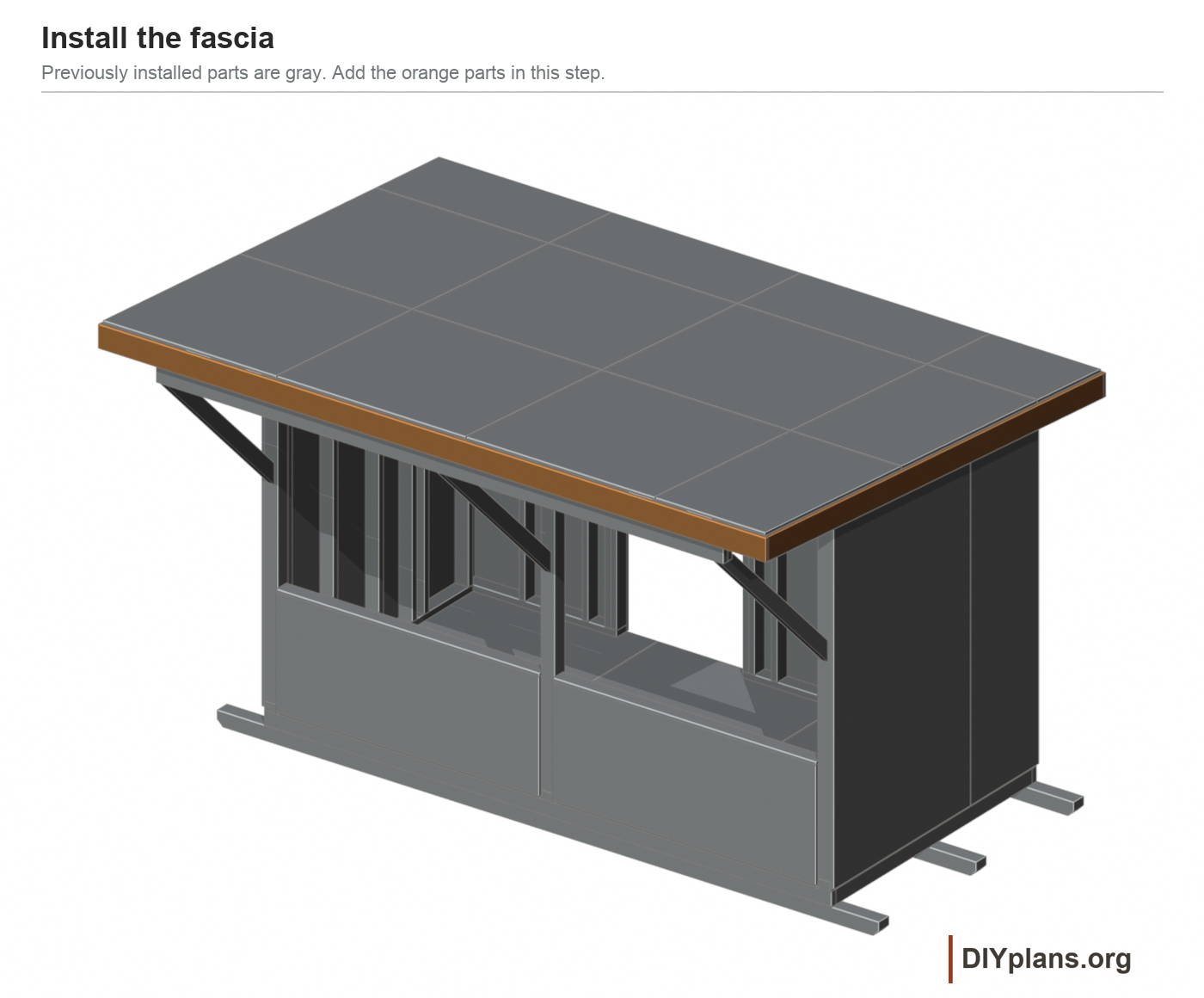
- Cut two 1x6 eave fascia boards to 169 1/2 in and the two sloping rake boards to the cut-list lengths. Seal their ends; fit the rake boards first, then the front and rear boards across their ends.
- Fasten each fascia to the rafter ends with two #10 x 2 in exterior screws per bearing. Predrill near ends and keep its upper edge aligned with the roof detail.
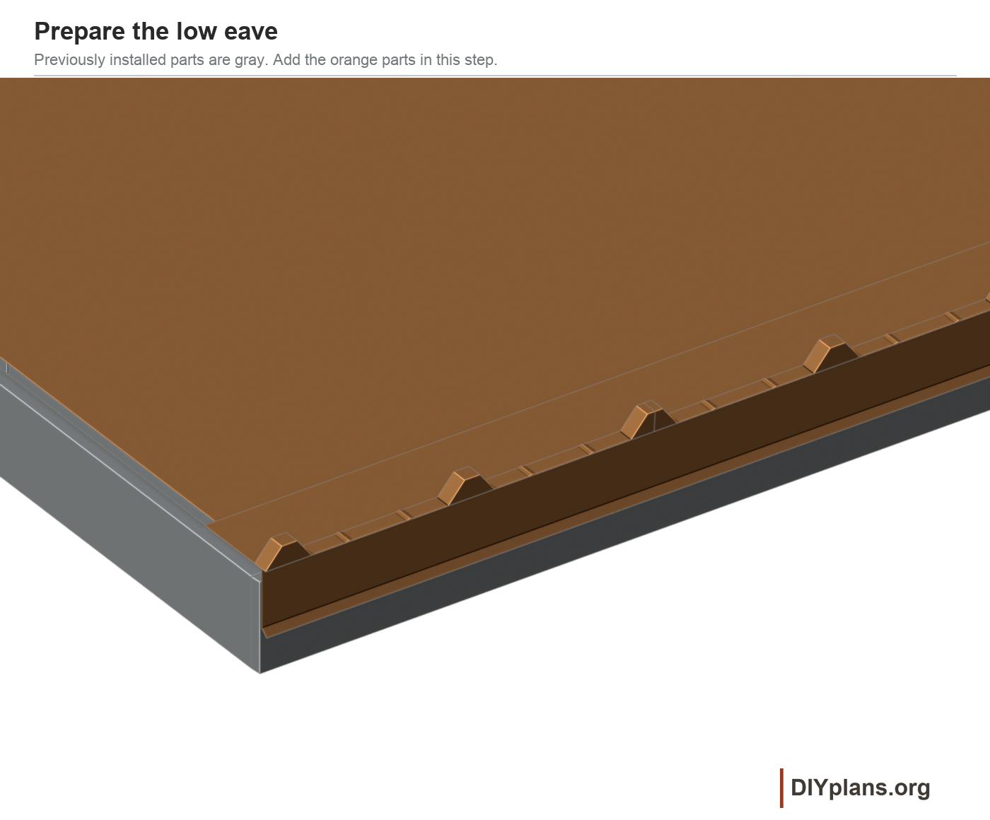
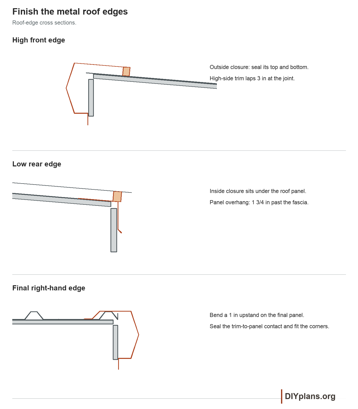
- Dry-fit two 86 1/4 in trim pieces at each front and rear edge, with 3 in laps for 169 1/2 in cover. Fit each 122 in rake run to the corners. Keep end-fitting allowance until the corners are formed. Set a string line 1 3/4 in horizontally behind the rear fascia face for the low panel ends.
- Lay the underlayment over the dry deck, starting at the low rear edge and working uphill. Follow its printed overlap lines and fastening or bonding instructions. Arrange the low-edge trim and underlayment so water exits over the drip edge, with no reverse lap.
- Fix the low rear trim into its solid fascia with #10 x 1 1/2 in washer-head wood screws at 12 in maximum spacing, using the ordered cleats where required. Seal its 3 in splice and bed the inside closures in matched 1 x 3/32 in tape on both faces. Leave the high-side outside closures and the rake covers off until the panels are installed.
Check: The deck is covered, the low edge drains outward and the panel layout can be marked without trapping water.

17 Lay the metal roof panels
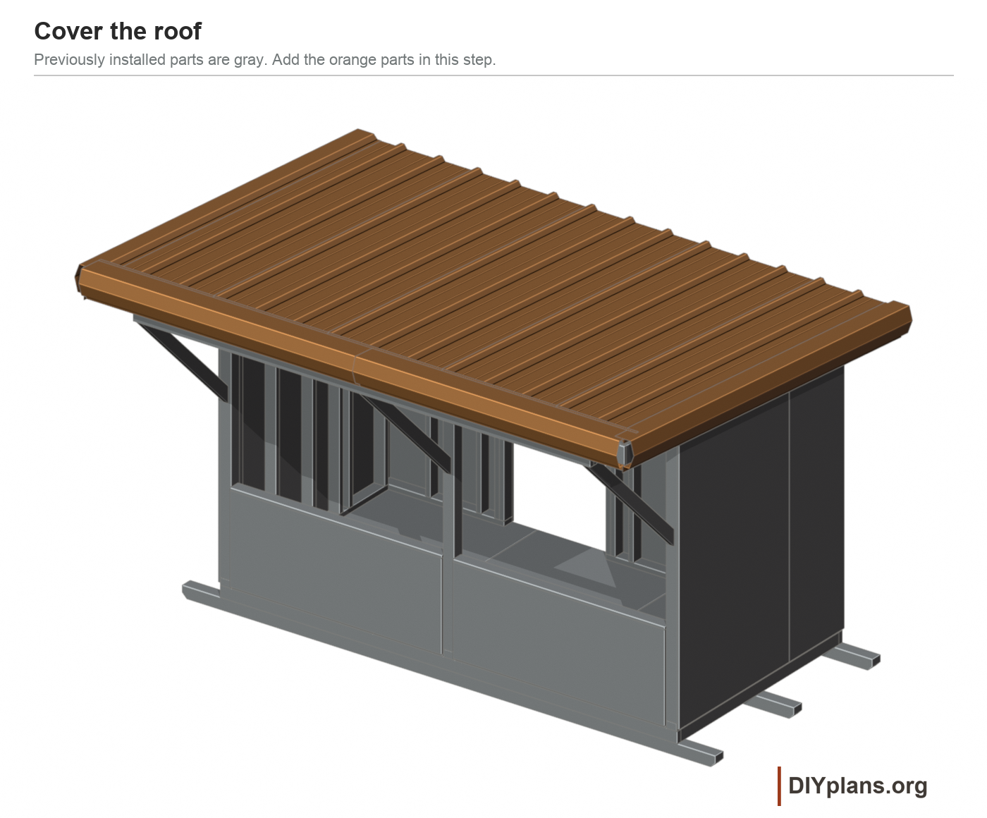
- On padded supports, check all five 122 in sheets and label their installation order. Run the ribs downhill from the front high edge to the rear low edge. Lay out four 36 in cover widths and the 25 1/2 in finishing width across 169 1/2 in.
- Nest the factory side laps in the direction shown in the metal layout; orient the sheltered lap away from the prevailing wind where the site permits. Square the first sheet to the rear eave and secure it without changing the 36 in cover width.
- Seal and fasten each side lap as the next sheet is placed. Keep all five low ends on one string line at the dimensioned overhang. Lift sheets into place instead of dragging them across the coating.
- Use 1/4-14 x 7/8 in lap screws, MBCI #4, at 20 in maximum spacing along each of the four laps. Apply continuous 1/2 x 3/32 in tape to the mating lap face before nesting each sheet. Put the seal between the exposed lap edge and screw line. Keep the tape joined at the closure seals. Fit all lap screws before covering the high edge.
- Fasten the panel flats into sound plywood. Keep holes clear of plywood butt joints and roof edges. Mark all rows before drilling; do not drive a roof screw into a gap or use the sign fasteners as roof screws.
- Use 1/4-14 x 1 in Type AB screws with sealing washers, MBCI #2B or the current plywood-roof equivalent. At each full-panel end use six screws in the flats beside the major ribs; use three per intermediate row. Mark rows 3, 27, 51, 75, 99 and 118 in from the high sheet end, along the slope. All six rows are over the deck; the four intermediate rows are no more than 24 in apart. Use the supplier's closer spacing where site exposure requires it. Preserve the corresponding rib pattern on the finishing strip, clear of its upturned edge. Drive square and seat washers evenly without stripping the plywood.
- Measure the remaining cover before trimming the final sheet. Preserve its mating lap, mark the 25 1/2 in cover line, and leave material outside that line for a 1 in upturned leg. Form the leg with a brake to the supplier's bend detail before fitting the rake trim.
- Collect metal chips and sweep them away after each cut or drilling session. Use snips or a nibbler for field cuts and deburr exposed edges. Keep the coating and sealing washers intact.
Check: Five full-length sheets lie square to the eave, with sealed side laps and a formed finishing edge.
18 Seal the metal roof edges
- Fit the outside closures across the front high edge with matched 1 x 3/32 in tape on both faces. Position the high-side trim so its roof flange shelters the closure by 1/2 to 1 in.
- Fit the starting rake over its rib and the finishing rake over the 1 in upturned leg. Place the matched tape below the contacting trim face. Close exposed trim ends with matching factory end caps or formed, sealed tabs made from the trim allowance. Leave no hollow profile ends open, and keep the corner returns draining toward the rear.
- Secure the high-side and rake trims. Keep the rear inside closures seated and the low drip edge unobstructed. Check every washer and remove swarf from the gutters of the profile.
- Use the matched lap screws at each major rib across the high-side trim, at 12 in spacing on the starting rake and at 6 in spacing on the finishing rake. Fasten trim faces with #10 x 1 1/2 in washer-head wood screws into the fascia at 12 in maximum spacing. Fit the ordered trim's cleats where required. Keep panel edges and closures supported. Seal both 3 in eave-trim laps and the folded corners with compatible urethane sealant.
- Install and flash the two raised hinge feet and two stay feet at their backed positions. Use the selected metal-roof boot or profile-fitted base detail, rigid spacers and through-bolts to framing; keep tightening loads off the unsupported sheet ribs.
- After the sealants permit wetting, apply a gentle water flow from the high edge. Inspect under the deck, around all four mounts and along the edges. Repair leaks before fitting the sign or stocking the stand.
Check: All four sign mounts and the roof perimeter shed water, and no fixing crushes a rib.
19 Build the rear door
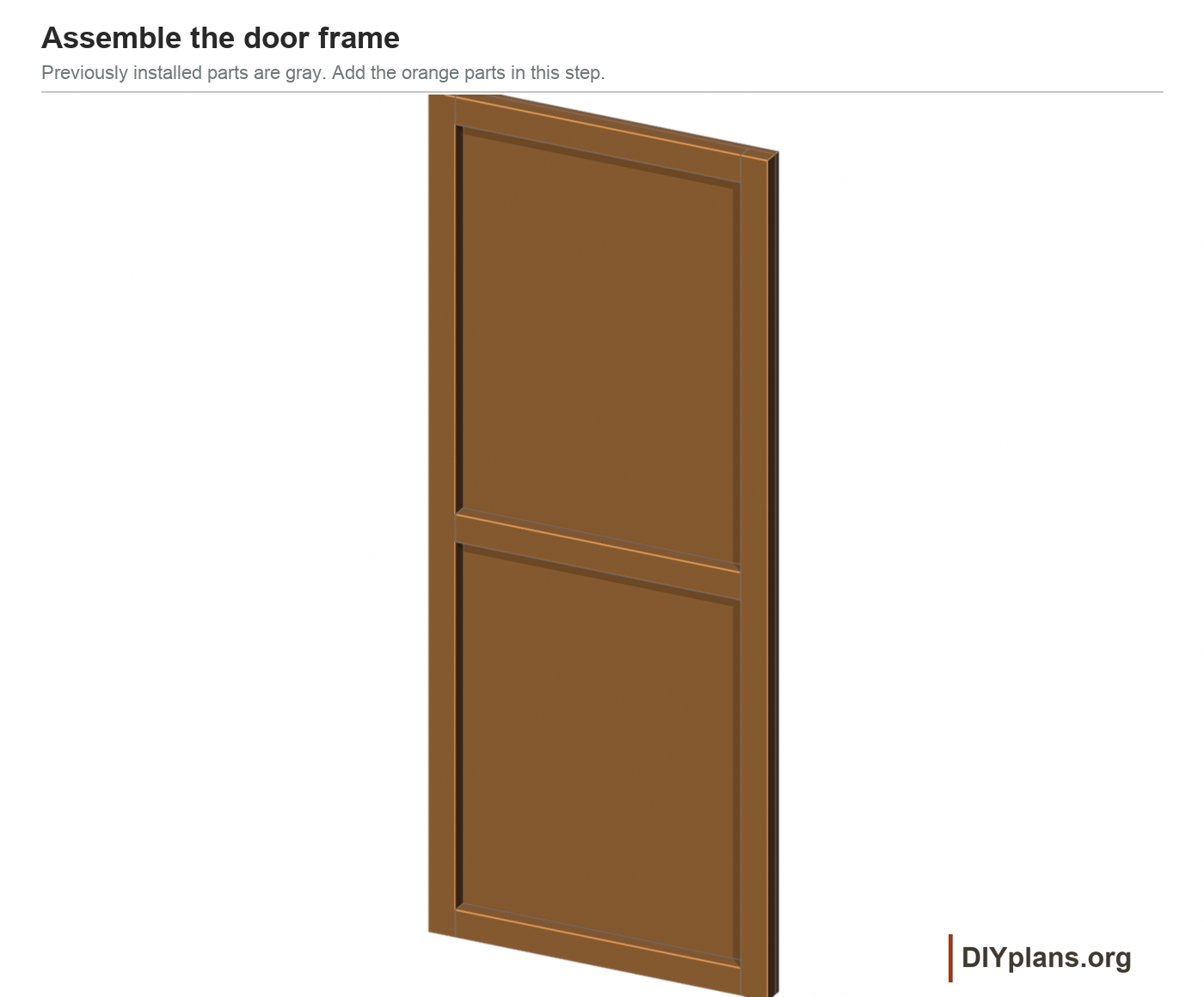
- Cut the door panel to 31 1/2 x 76 1/2 in. Cut two 2x3 stiles to 76 1/2 in and two rails to 26 1/2 in.
- Lay the frame flat, with the rails between the stiles and the outside corners square. Pilot and join each rail end with one 4 in structural screw through the stile; the screwed plywood panel completes the door frame.
- Fit a 26 1/2 in 2x3 middle rail between the stiles, with its center 37 1/4 in above the leaf bottom, to back the middle hinge strap. Its bottom will be 44 in above the skid bearing plane when the door is hung.
- Screw the panel into every frame member. Seal the bottom edge, all cuts and both faces before hanging.
- #10 x 2 in exterior screws at 6 in around supported edges and along the counter rails. Predrill and set heads flush. Use two rows along each fixed hinge cap, staggered at 12 in. Keep every counter hinge strap hole over full-depth backing. Do not drive a screw into an unbacked skin.
Check: The door leaf is square, fully framed and measures 31 1/2 x 76 1/2 in.
Play movementStop movement
20 Hang the rear door
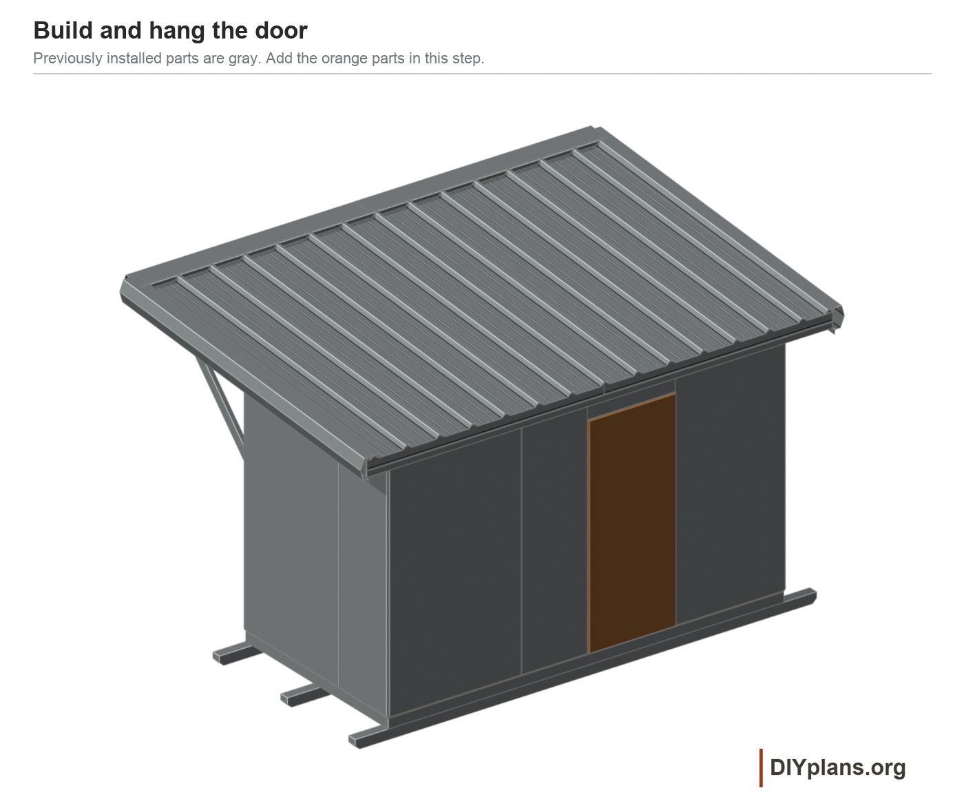
- Pack the leaf in the 32 x 77 in opening with 1/4 in clearance at the head, sill and both jambs.
- Align three hinge pins on the left jamb. Put the upper and lower straps over the door rails and the middle strap over its backing; use the fastening detail below for mounting.
- Per hinge: four #14 x 2 1/2 in structural screws into the hinge jamb; four 1/4 x 3 in through-bolts into the door frame. Place top and bottom straps across the door rails. Provide full backing behind the middle strap. Keep bolt heads on the outside, washers and locknuts inside. Fill every required mounting hole.

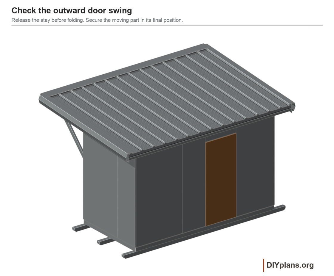
- Swing the door outward with a helper holding its weight. Check the rear skid, latch side and door-head flashing before removing the packers.
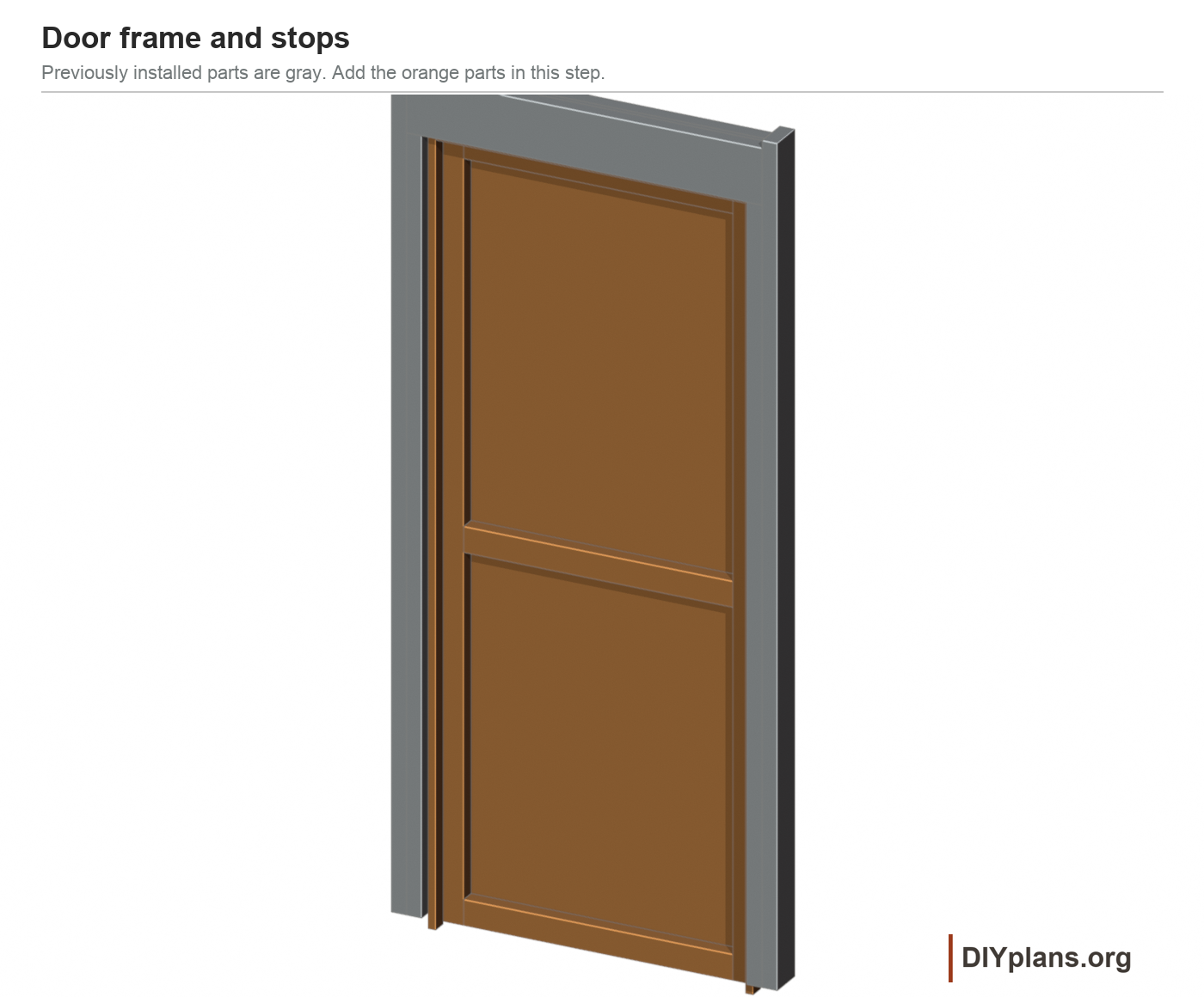
- Fit the two 77 in 1x2 side stops and the 30 1/2 in head stop to the closed door, then add weatherstrip, the latch and the hold-open catch. Leave the latch operable from inside.
- Keep hands away from the hinge gap while cycling the leaf.
Check: The door opens fully, latches without lifting and compresses its weatherstrip evenly.
21 Build the counters
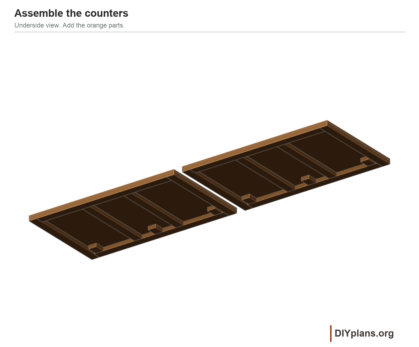
- Build two counter frames from flat 2x4s. Each uses two 40 in end rails, two 59 1/2 in long rails between them and two 33 in cross rails.
- Place the cross-rail left edges 22 and 41 in from each counter's left edge. Keep the frame square at 66 1/2 x 40 in overall.
- Fit three flat 2x4 hinge-backing blocks to each counter, each cut to 4 1/2 in. Center them 6, 33 1/4 and 60 1/2 in from the counter's left edge, against the front face of its rear rail. Each block continues the rail backing to 8 in forward of the counter's rear edge; use the fastening detail below before bolting the hinge straps.
- One 5 in exterior structural timber screw through the rear rail into each 4 1/2 in block, plus two #10 x 2 in screws through the plywood into each block; six long screws and twelve skin screws total. Lay the six 2x4 blocks flat, centered below the hinge straps, with their tops flush with the rear rail. Pilot the rail-to-block screw. Keep skin screws clear of the hinge bolt holes; through-bolt the straps only after the backing and skin are fixed.
- Join the flat-frame butt joints. Lay a 66 1/2 x 40 in 3/4 in plywood top over each frame and screw it to every rail.
- One 5 in exterior structural timber screw at each butt joint, plus the screwed plywood top. With the 2x4s flat, center the screw through the wide passing member into the mating rail. Pilot to prevent splitting. The top must be attached to every rail before moving the panel. The assembly has no stated load rating.
- #10 x 2 in exterior screws at 6 in around supported edges and along the counter rails. Predrill and set heads flush. Use two rows along each fixed hinge cap, staggered at 12 in. Keep every counter hinge strap hole over full-depth backing. Do not drive a screw into an unbacked skin.
- Round sharp exposed edges lightly and seal both faces and all edges. Keep the underside clear where the legs must fold.
Check: Both counter panels are square and every moving hinge hole has solid backing.
22 Fit the folding legs
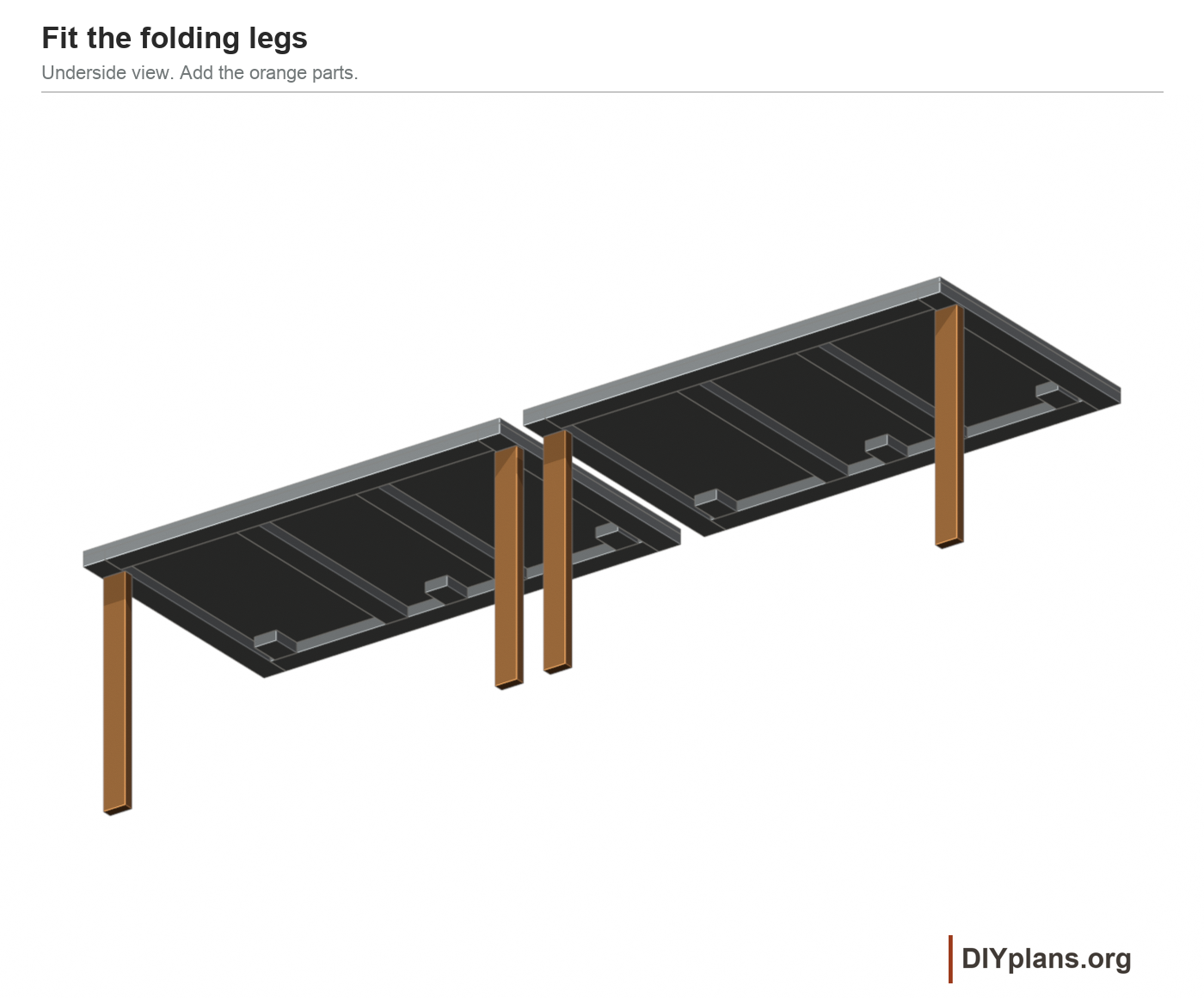
- Cut four 2x4 legs to 33 3/4 in and treat their bottom ends. Fit two to each counter using the positive-locking leg brackets.
- Set the leg hinge line 35 1/4 in ahead of the front framing line and 33 3/4 in above the skid bearing plane. The legs fold toward the building, beneath the counter.
- Dry-fit the brackets on the counter end rails using their mounting templates. Check that the legs contact the frame when extended and both locks engage.
- Fold each leg through 90 degrees toward the rear and fit its retaining clip. Check all bolts, brackets and backing clear the folded legs before drilling remaining holes.
Check: All four legs lock open and clip flat beneath their counter without collision.
23 Hang the counters
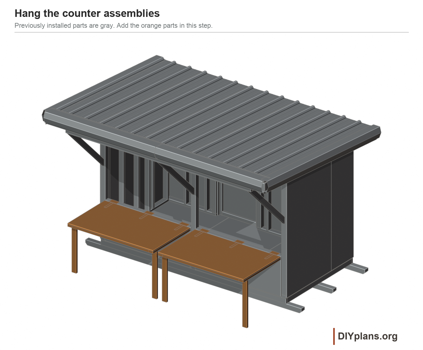
- Clamp stable temporary props under one counter and bring its top level with the 36 in hinge cap. Use a helper to hold the panel throughout fitting.
- Leave a 1/4 in gap between the counter's rear edge and the cap's front edge. Center the panel in its bay, with 1/8 in clearance at each side.
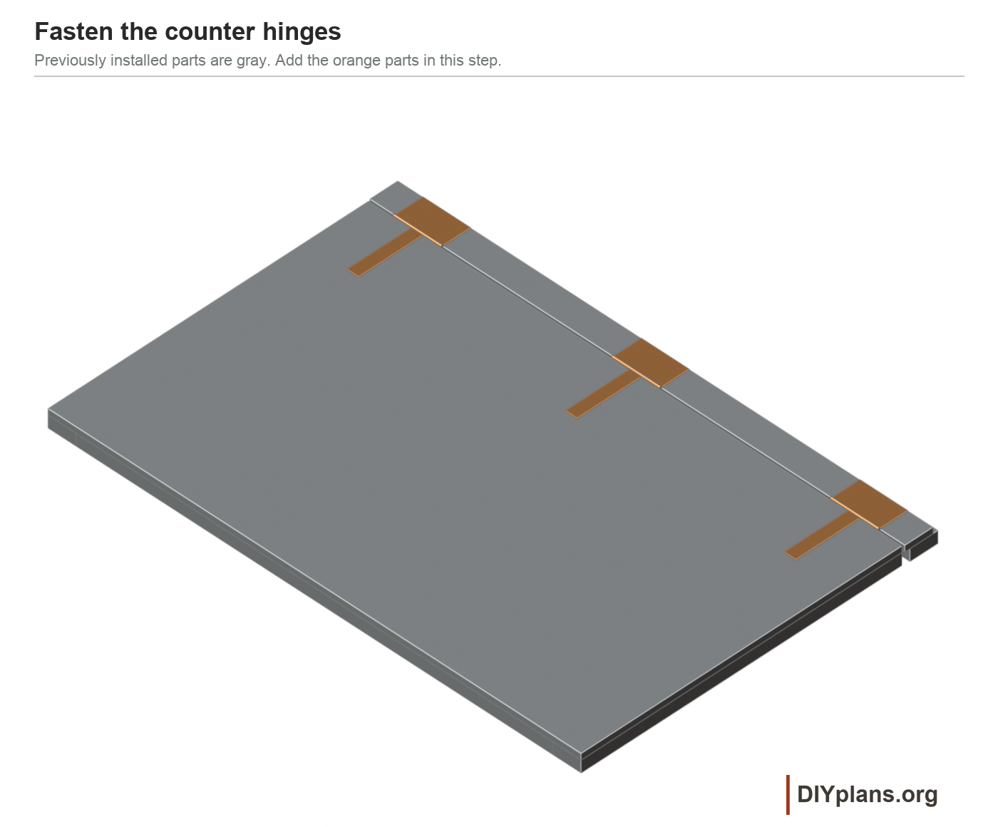
- Lay the three 8 in tee hinges flat across the cap and counter top at the marked centerlines. Run each moving strap forward over its backing. Keep all hinge pins on one straight line, 36 1/8 in above the skid bearing plane.
- Pilot the fixed leaves into the cap and underlying plate; through-bolt the moving straps into the counter frame. Fit the positive closed-position latches to solid posts and end rails.
- Per hinge: four #14 x 2 in structural screws into the fixed cap and its top plate; four 1/4 x 3 in through-bolts into the counter frame. Use the selected hinge's complete hole pattern. Fit wide washers and locknuts below the moving frame. Put any additional backing under the full moving strap before bolting. Keep the axis straight and the gap clear.
- Repeat for the other bay. Keep props in place and hands out of the pin line until the legs, chains and latches have been checked.
Check: Each counter is level on its props, has the specified gaps and moves without binding.

24 Fit the counter chains
- Keep both counters supported on props. Extend and lock all four legs onto firm pads at the skid bearing plane; fit the foot contact so the counter tops remain 36 in above that plane.
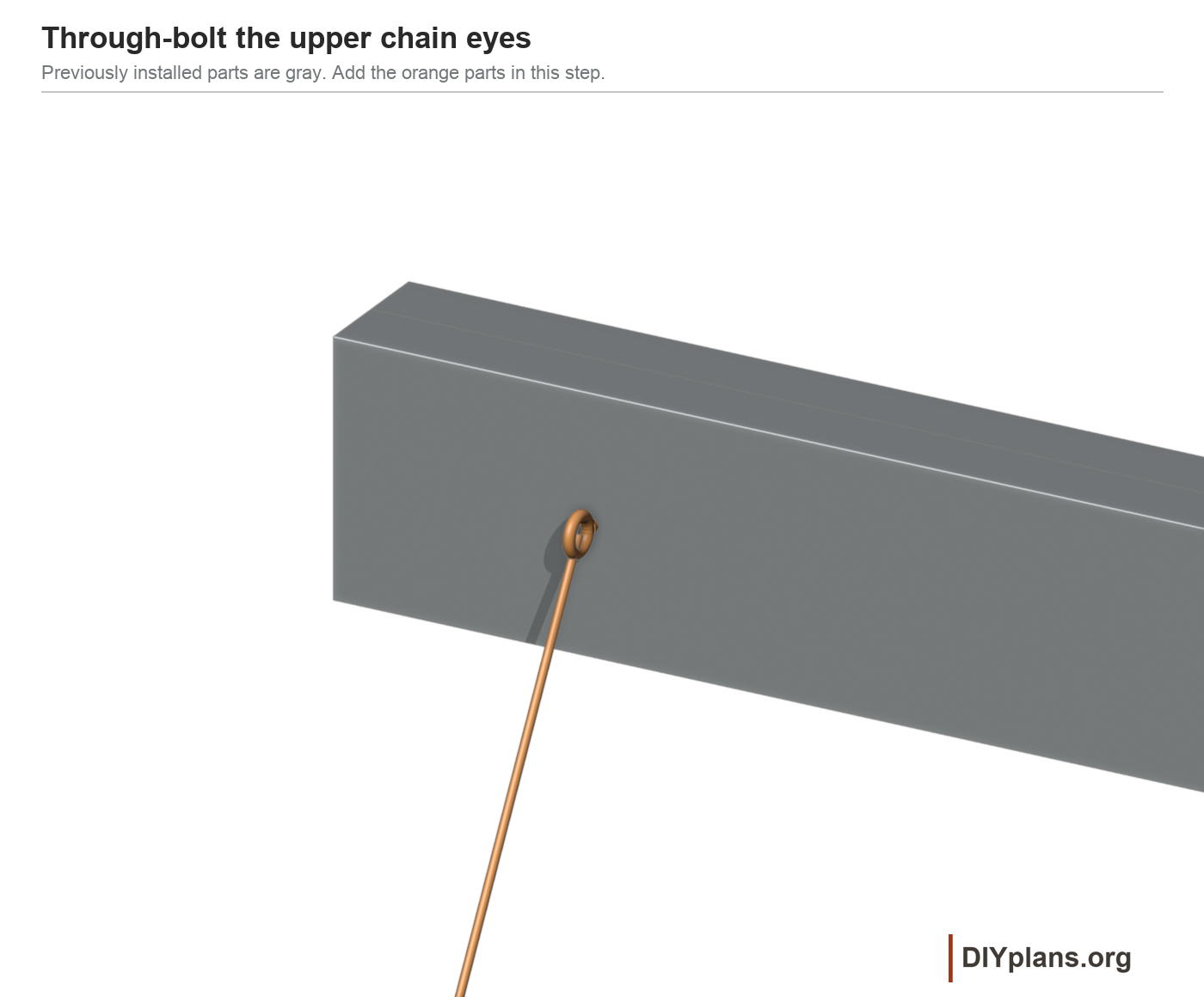
- Mark four upper eye holes at 5 5/8, 68 1/8, 75 7/8 and 138 3/8 in from the left floor edge, all at 97 1/4 in above the skid bearing plane. Drill through both plies of the solid front header and fit forged closed shoulder eyebolts with wide washers and locknuts behind the full 3 in beam.
- Set each upper eye center 1/2 in ahead of the header front face, at y = -1/4 in on the detail. Use a shank long enough to pass the whole beam and the rear washer and locknut; use through-bolted eyes, not screw-in eyes.
- Through-bolt the lower eyes through the counter end-rail assemblies near the outside front corners. Keep the bolts clear of leg brackets and provide wide washers against the framing.
- Fit the four chain lengths with upper threaded quick links and lower gated detachable connectors. Shorten them link by link while the counter is level; keep both sides even and all legs bearing.
- Install four chain-storage hooks inside the stand. Check that an unhooked chain can hang clear of the counter and door before removing the props.
Check: Both counters remain level with four locked legs, four attached chains and secure eyes.
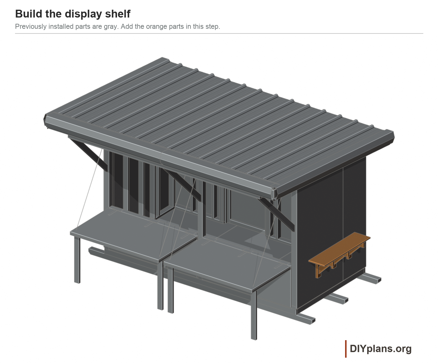
25 Fit the side shelf
- Make three brackets, each with a 10 1/2 in 2x4 wall cleat, a 12 in 2x4 arm and a diagonal brace with 8 in horizontal and vertical long-edge runs. Cut its ends at 45 degrees; its long edge is about 11 5/16 in.
- Assemble the brackets. Set the wall-cleat bottom 21 1/4 in above the skid bearing plane and its top at 31 3/4 in, directly beneath the arm.
- Three 4 in structural screws per wall cleat; two 3 in framing screws at each arm-to-cleat joint; two 3 in framing screws at each brace end. Assemble each bracket on the bench. Pilot screws from the back of the cleat into the arm and lower brace before mounting. Angle the upper brace screws into the arm. Fasten the cleat on the wall-stud centerline, through siding into the stud.
- Fasten the cleats over the right-wall studs whose front faces are 19 1/2, 35 1/2 and 51 1/2 in behind the front floor line. Put all wall screws on the stud centers.
- Fit the 48 x 12 in plywood shelf with its front end 12 in behind the front floor line. Its top is 36 in above the skid bearing plane. Screw it into all three arms and seal its edges.
Check: The shelf is level, all three cleats fasten into studs and every brace bears tightly.
Play movementStop movement

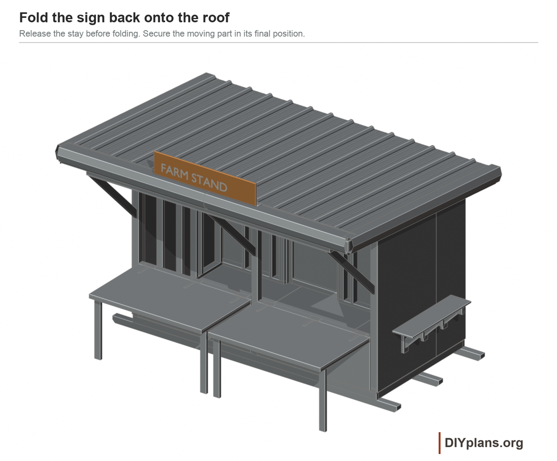
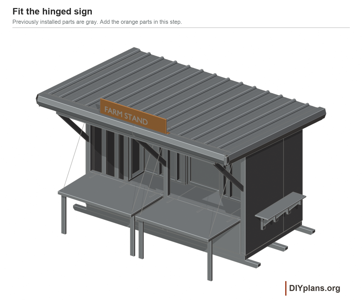
26 Fit the farm sign
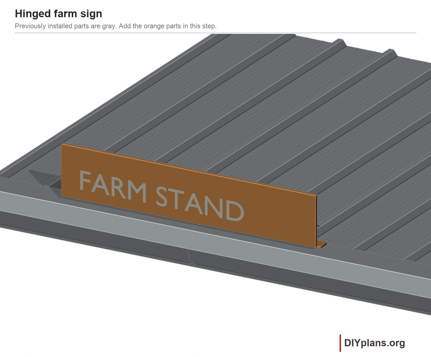
- Cut and finish the 60 x 12 in plywood sign. Center it across the front roof edge, with its left edge 42 in from the left floor edge.
- Fit the two raised hinge assemblies to the backed mounting lines and set the pivot at 111 1/2 in above the skid bearing plane. Through-bolt the sign with wide backing washers or plates. Its upright top is 123 1/2 in above that plane.
- Attach both locking stays to the flashed raised feet on the 48 and 96 in rafter centers, 27 in ahead of the front wall. Fit the supplied rigid spacers and backing washers; snug the bolts without deforming the cladding.
- Support the sign with a helper and move it slowly from upright to folded back. Keep its lower edge, hinges, stays and bolt ends clear of every rib and the high-side trim throughout the swing. Keep fingers out of the hinges and stay joints.
- Fit two 3 x 3 in tapered resting pads to the high-side trim, with their tops at 110 3/4 in above the skid bearing plane. Bond them with compatible adhesive and fit both transport catches. Lock both stays upright, then release and stow them under control and latch the sign folded. Recheck the four mount seals after tightening.
Check: The sign locks in both positions, clears the metal roof throughout its swing and rests on the prepared pads.
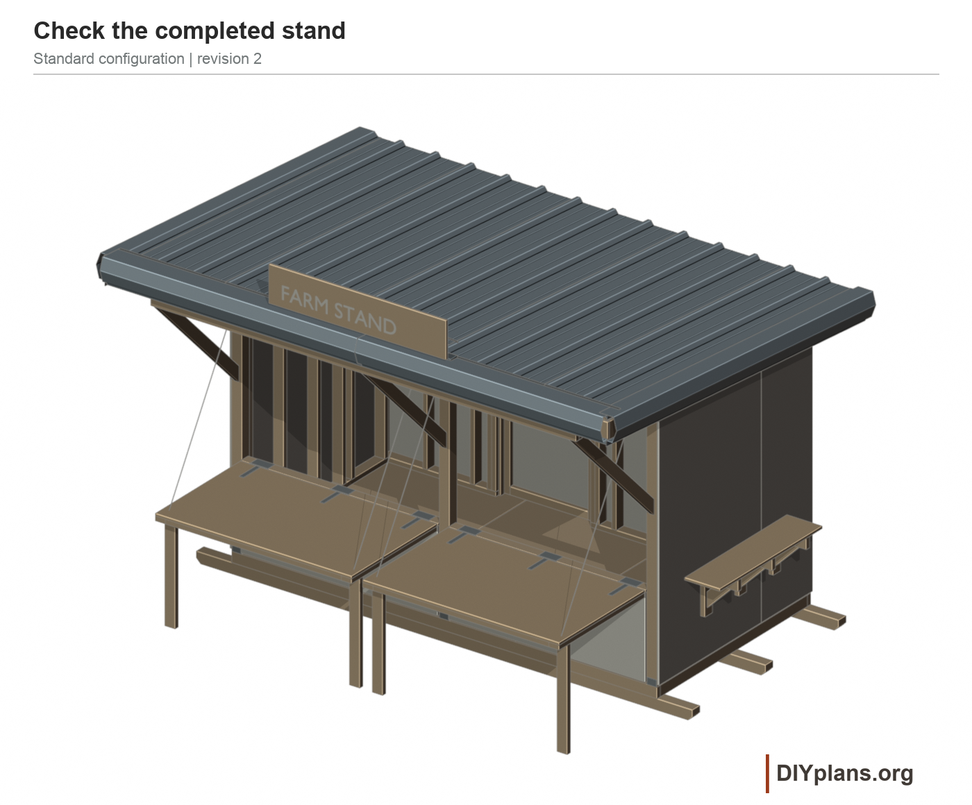
27 Finish and check the stand
- Finish exposed wood and reseal field cuts, keeping paint off hinges, roofing seals and hardware bearing surfaces. Let all coatings cure before stocking; remove the last metal chips and inspect the panel coating.
- Complete and tension the selected site anchors. Inspect the full connection path from skids through wall framing and roof ties to the roof edges.
- Check the floor, counter and shelf heights, all four leg locks, chain gates, counter latches, door latch and sign stays. Remove temporary props only after these checks.
- Set a few small display containers over supported rails and check for rocking or movement. Keep bulk storage low inside the stand, clear of the door; this check does not establish a load rating.
- Keep washable trays between produce and the finished wood. Leave the sales area and rear exit clear of legs, anchor ties and stored chains.
Check: The stand is anchored, dry, stable and ready for attended display within the stated construction limits.
Play movementStop movement

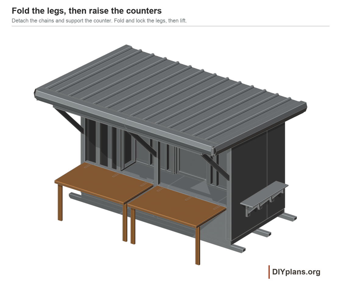
28 Fold the counters closed
- Remove everything from both counters. Have a helper support one counter and place a stable temporary prop beneath it before releasing any support.
- Open its two lower chain connectors and detach the chains from the counter. Hang them on the inside storage hooks, clear of all moving parts.
- With the counter still supported, release each leg lock. Fold the legs up 90 degrees toward the rear first and secure both retaining clips.
- Keep hands off the hinge gap. With the helper carrying the panel, remove the prop and lift the counter upward 90 degrees into the opening. Stop if a leg, hinge or chain catches.
- Engage both counter latches before letting go. Repeat on the second counter; fold and catch the sign, then close and latch the rear door.
Check: Both counters are positively latched with legs clipped underneath and chains detached and stowed.
29 Open the stand for use
- Inspect the base and anchors before opening. Check for soft ground, loose screws, damaged chain links, split backing and roof leaks; correct the fault before loading the affected part.
- Support one counter with a helper, release both latches and lower it onto a stable prop. Keep the legs folded until the counter is horizontal.
- Swing both legs down and engage their positive locks. Seat their feet on the prepared pads, then reconnect both lower chain connectors and close their gates.
- Check the counter level and all supports before removing the prop. Repeat on the second counter, then open and secure the door and raise and lock the sign.
- Close the stand when unattended or before strong winds. Recheck feet, hinges, roof screws, flashing and anchors after moving the stand or after severe weather. Arrange snow removal from the ground without scraping the coating or deforming panels; keep the rear exit clear.
Check: Every open counter has two locked legs and two connected chains; the door and sign are secured.
Sources
Prepared for DIY Plans using construction information from Movable Roadside Stand, plan 5699, Florida Agricultural Extension Service, University of Florida College of Agriculture, with USDA cooperation; hosted by NDSU. Scene lighting and textures include CC0 assets from Poly Haven.
- Movable Roadside Stand, plan 5699
- Kloppenheim 05 HDRI, Greg Zaal, Poly Haven, CC0
- Gravel Floor, Matterfield and Jenelle van Heerden, Poly Haven, CC0
- Aerial Grass Rock, Rob Tuytel, Poly Haven, CC0
- Weathered Planks, Dimitrios Savva and Dario Barresi, Poly Haven, CC0
- MBCI PBR panel product details
- MBCI PBR/PBU installation manual, PB28, PB32 and PB33
- MBCI PBR wood-deck attachment detail PBR-W-ELP-01