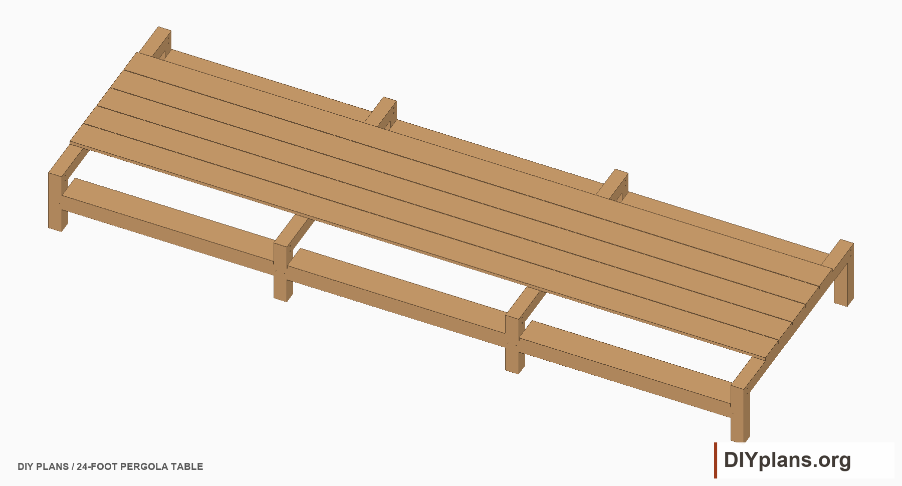
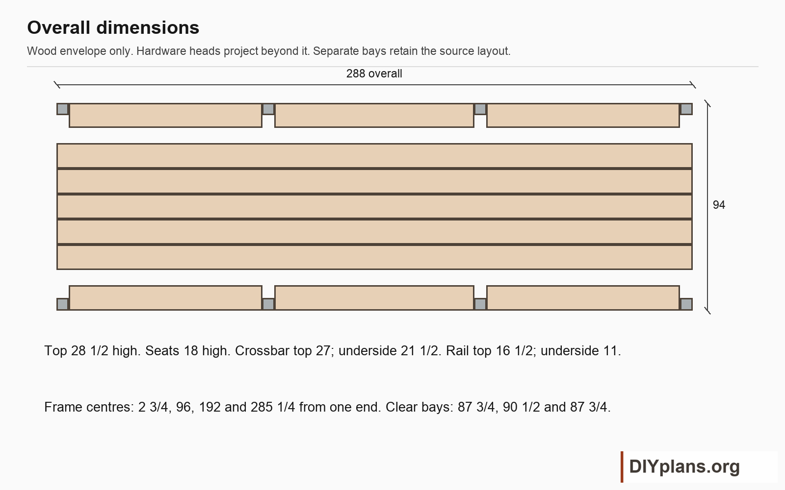
BEFORE YOU BUILD
Use this work at your own risk
These files have not been checked for accuracy, safety, structural adequacy, or building-code compliance. They may contain serious errors and are not construction-ready. Obtain independent qualified design and review before building.
No person or organization makes any guarantee or warranty, express or implied, regarding this design, its documentation, digital files, or website views. They are not professional services and do not create an architect-client or other professional-client relationship. No promise is made about accuracy, completeness, reliability, code compliance, or fitness for your project.
Buildings and building projects are complex, and many things can go wrong. You are responsible for checking dimensions and site conditions, choosing suitable materials and methods, obtaining permits, following codes and manufacturer instructions, and getting qualified professional help when needed. To the fullest extent permitted by law, DIYPlans.org disclaims liability for damages resulting from use of this work. Read the FAQ about your responsibilities.
Instructions
Step 1 Check and cut the stock
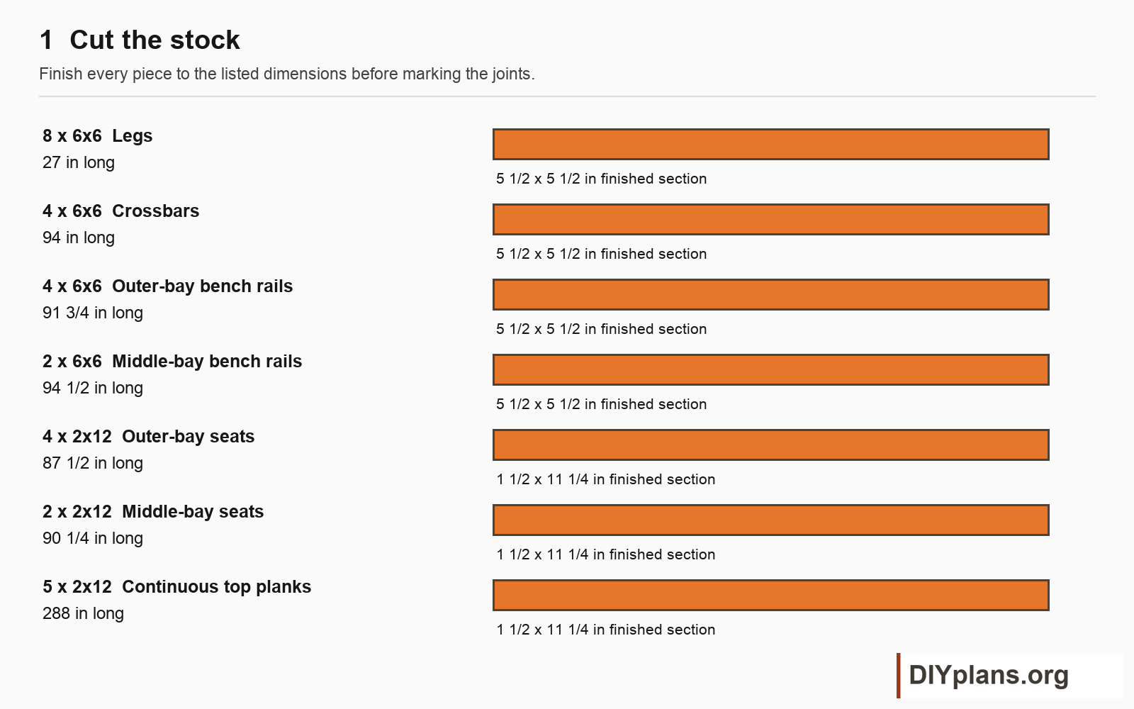
- Measure the actual board thicknesses and widths. Stop and revise the model if they differ from the scheduled sections.
- Crosscut and label the eight legs, four crossbars, six rails and six seats. Keep the longer middle-bay pieces separate.
- Trim the five top planks to 288 in only after confirming the final frame layout. Reserve straight, sound stock for the long spans.
Check: Count 29 wood parts. All ends are square; the top boards have no splice.
Step 2 Mark the leg joints
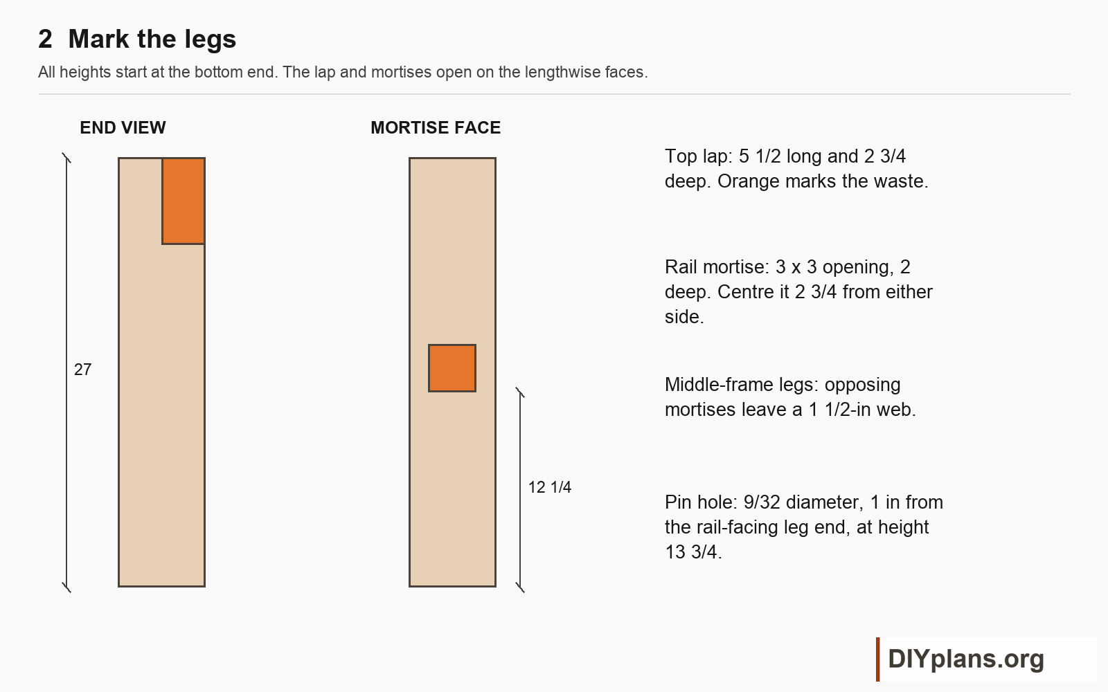
- Mark every leg from its bottom end. Mark the top lap from 21 1/2 to 27 in, removing 2 3/4 in from the same longitudinal half of each leg.
- Mark each rail mortise 12 1/4 to 15 1/4 in above the foot and centred across the 5 1/2-in leg width. Cut it 3 in wide and 2 in deep from the rail-facing end.
- Cut one mortise in each end-frame leg. Cut opposing mortises in each middle-frame leg, leaving a 1 1/2-in web. Keep the outer side faces intact.
- Fit a trial 3 x 3-in tenon in scrap. Adjust for a snug sliding fit before cutting all joints.
Check: The rail shoulders will finish at 11 and 16 1/2 in above the foot.
Step 3 Assemble the cross frames
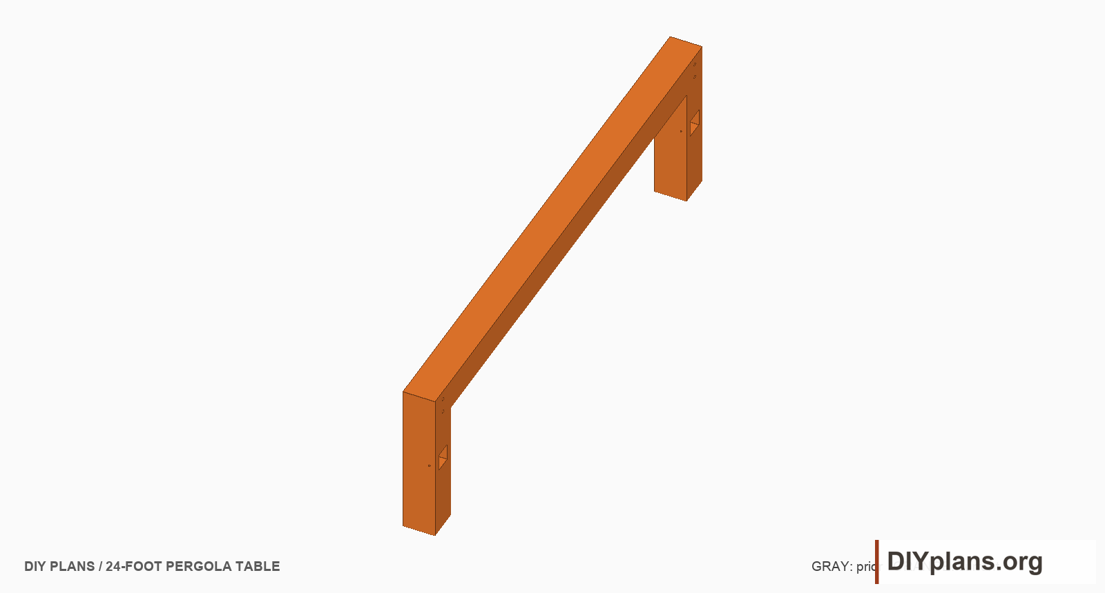
- Cut the complementary 5 1/2-in-long, 2 3/4-in-deep lap at each end of every 94-in crossbar.
- Clamp one crossbar to its two legs. Keep the crossbar top 27 in above the feet and the outside leg faces 94 in apart.
- Match-drill 9/16-in holes along the table length at 23 and 25 1/2 in above the feet, centred 2 3/4 in across each leg. Fit two 1/2-in bolts per joint.
- Repeat for the remaining three frames and label them 1 to 4. Keep them movable until the bench rails are fitted.
Check: Each frame has equal diagonals and coplanar feet. Tighten without crushing the wood.
Step 4 Cut the bench-rail tenons
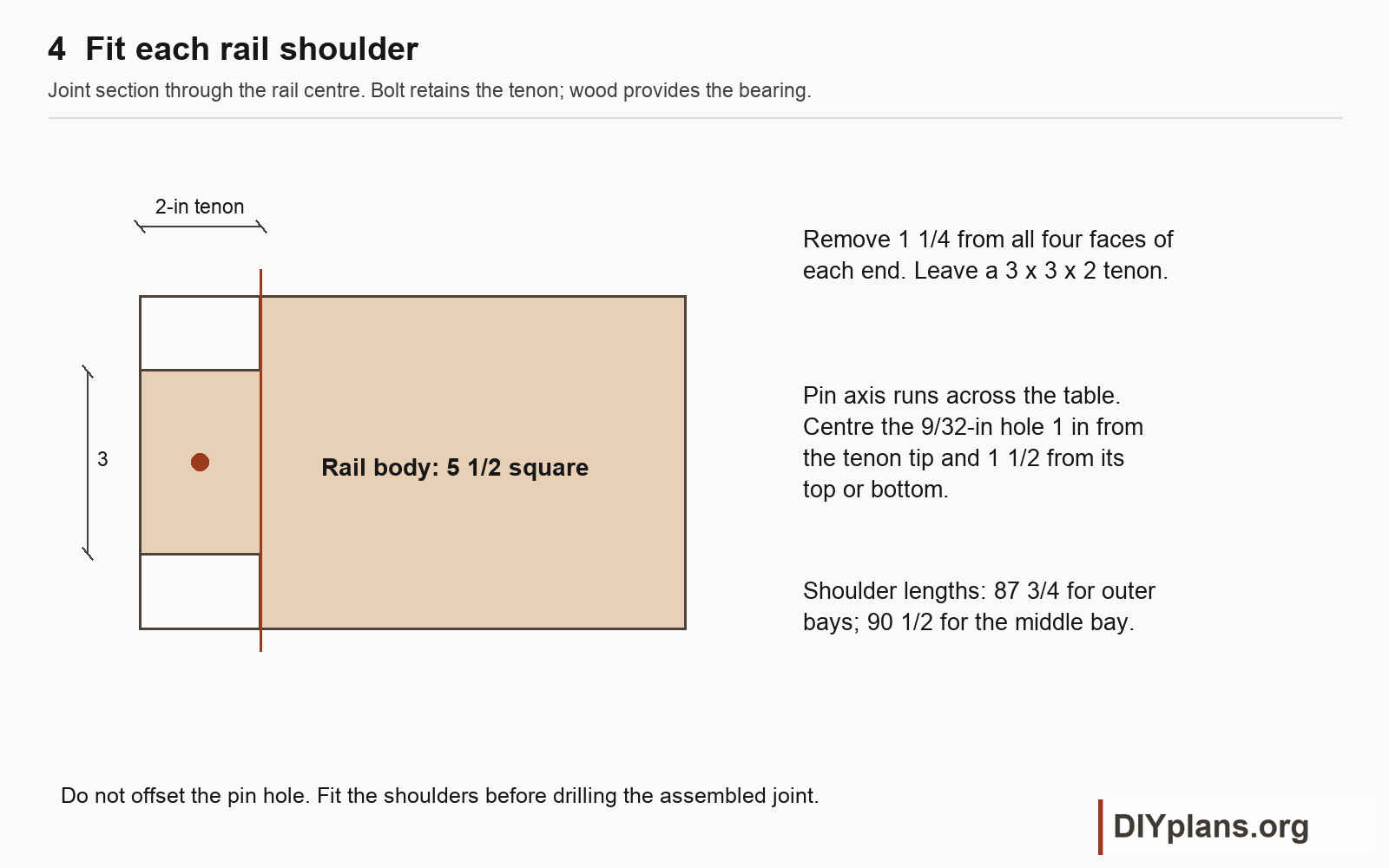
- Mark a 2-in shoulder at each end of every rail. Leave a centred 3 x 3-in tenon by removing 1 1/4 in from each face.
- Keep 87 3/4 in between shoulders on the four outer-bay rails and 90 1/2 in on the two middle-bay rails.
- Mark each retaining-bolt line 1 in from the tenon tip and centred through the tenon height. Do not drawbore or offset these holes.
- Dry-fit the rails to the corresponding mortises. Keep the shoulders square and fully seated.
Check: The middle rail is 94 1/2 in overall; each outer rail is 91 3/4 in.
Step 5 Join the first bay
Play animationStop animation
 Loading image
 Loading image
- Stand frame 1 on the level base and brace it temporarily. Insert both first-bay rails into its mortises at the same time.
- Support the free rail ends at the correct height. Slide frame 2 onto both tenons until every shoulder closes. Keep hands away from closing joints.
- Match-drill 9/32-in holes across the table width through the leg and tenon at each marked pin line. Fit the four 1/4-in retaining bolts and washers.
- Check 93 1/4 in from the outer end of frame 1 to the leading face of frame 2. Do not use the bolts to pull a badly fitted joint closed.
Check: The clear first bay is 87 3/4 in; the rail tops are 16 1/2 in above the base.
Step 6 Add the middle bay
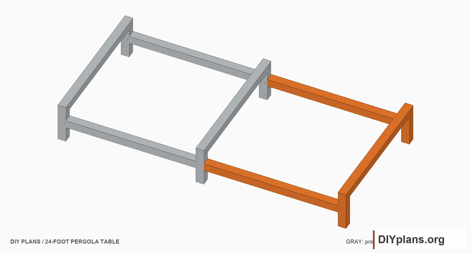
- Insert the two longer rails into frame 2. Support them and slide frame 3 onto both free ends.
- Seat the shoulders, then match-drill and install four retaining bolts as for the first bay.
- Measure the leading face of frame 3 at 189 1/4 in from the same outer end. Check the base diagonals and frame alignment.
Check: The middle clear bay is 90 1/2 in. Both middle frames stay upright and parallel.
Step 7 Close the final bay
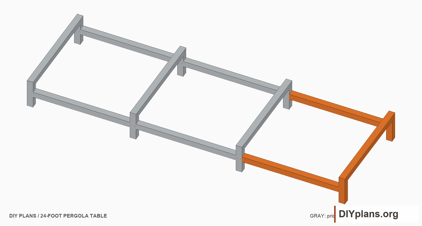
- Insert the remaining two outer-bay rails into frame 3 and slide frame 4 onto their ends.
- Install the last four rail retaining bolts. Align the leading face of frame 4 at 282 1/2 in.
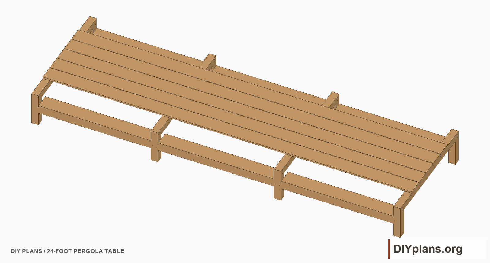
- Check the complete frame measures 288 x 94 in across its outer wood faces. Adjust the base so all eight feet bear before removing temporary braces.
Check: All rail shoulders close and the four crossbar tops share one plane.
Step 8 Fit the six seats
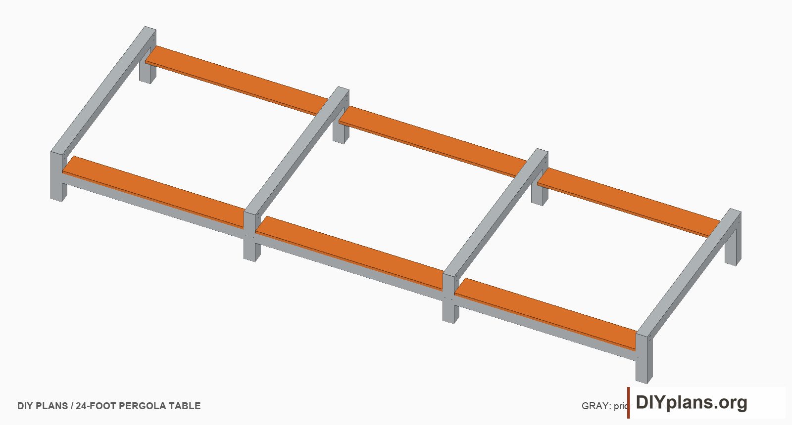
- Position the two longer seats in the middle bay and the four shorter seats in the outer bays. Keep 1/8 in clear at each leg.
- Align each seat outside edge with the outside of the frame. The seat projects 5 3/4 in inward beyond its bench rail.
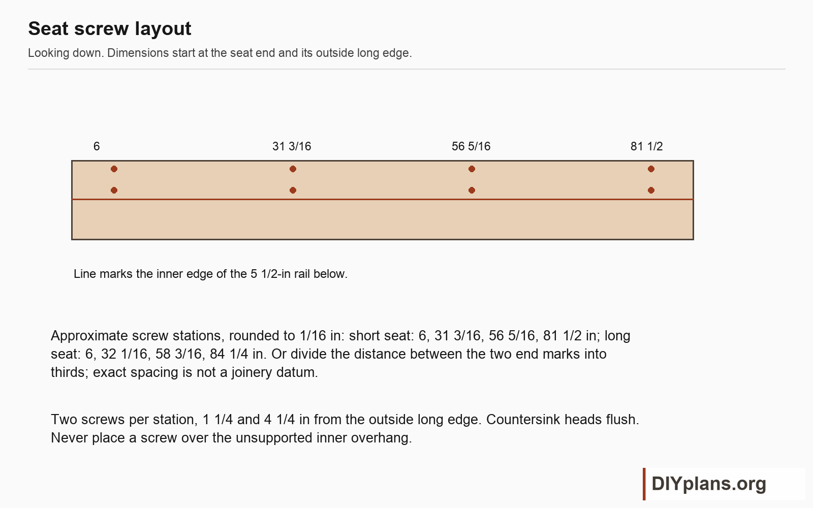
- Use four screw stations along each seat, 6 in from the ends and evenly spaced between. At each station, place screws 1 1/4 and 4 1/4 in from the outside edge.
- Drill clearance holes through the seat and manufacturer-sized pilots into the rail. Drive eight #12 x 3-in screws per seat with heads flush.
Check: Every screw enters the rail. Seats finish at 18 in and do not bridge the leg gaps.
Step 9 Position the first top plank
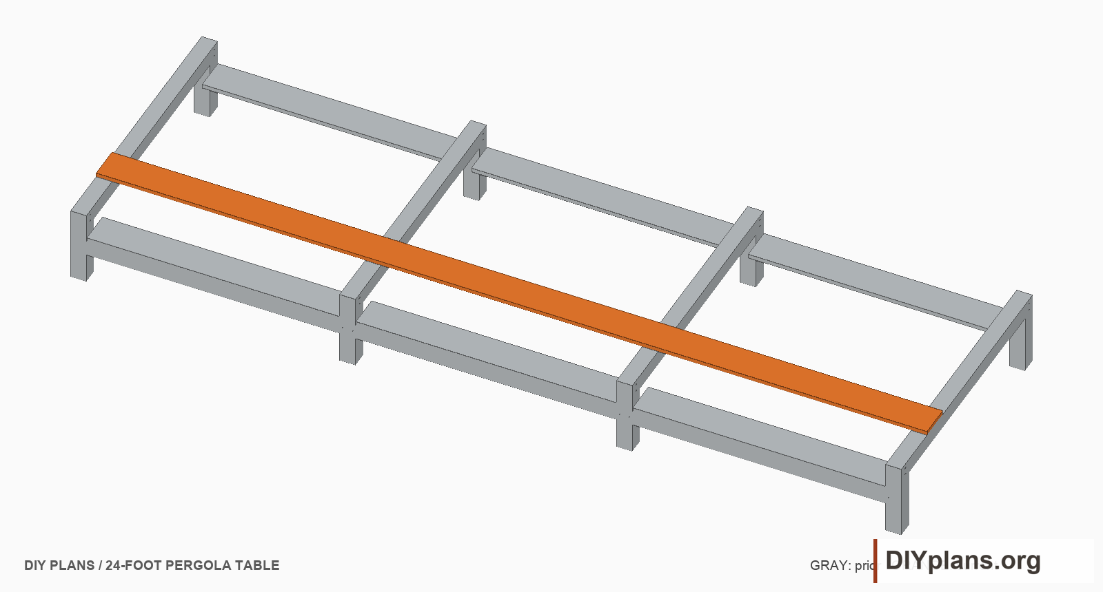
- Mark the first tabletop outside edge 18 3/8 in from the near outside frame edge.
- With the planned lifting assistance, set the first 24-ft plank across all four crossbars. Align both ends with the outer frames.
- Use one #12 x 3-in screw on the plank centreline at each crossbar centre, measured from one end at 2 3/4, 96, 192 and 285 1/4 in.
- Drill board clearance holes and manufacturer-sized pilots. Keep the screw heads flush and the plank edges free to move across their width.
Check: The first plank bears on all four crossbars without rocking.
Step 10 Complete the tabletop
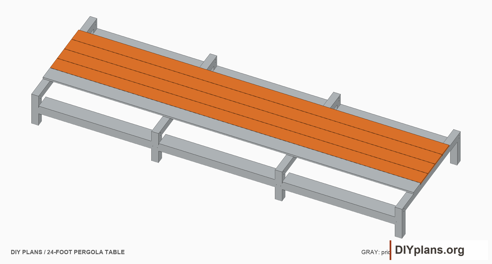
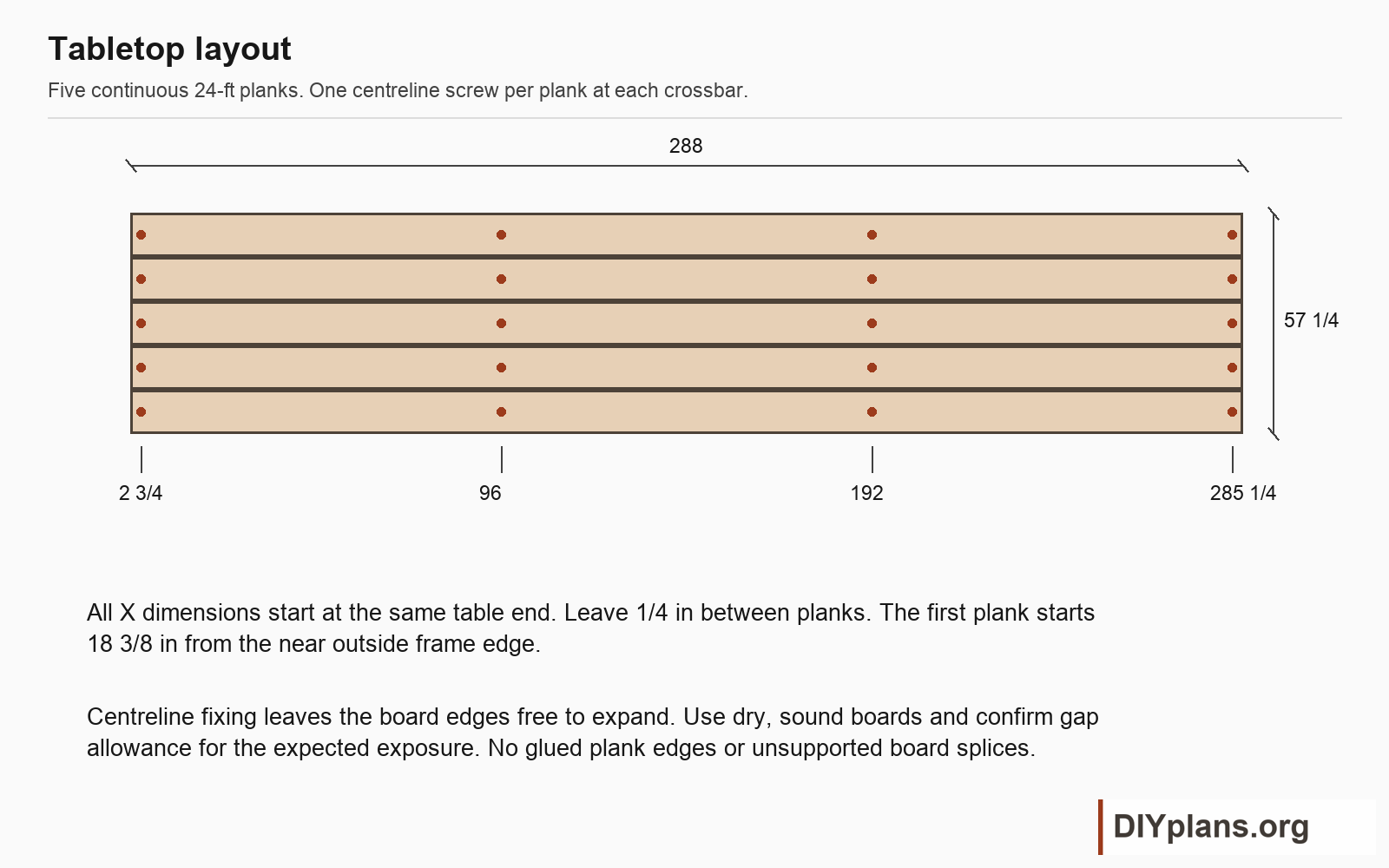
- Set the remaining four planks with 1/4-in spacers between their long edges. Keep the ends aligned.
- Fasten each plank through its centreline at the four crossbars. Use 20 top screws total. Do not glue the edges or add fixed fasteners near both edges.
- Check the final tabletop width is 57 1/4 in and the outside margins are 18 3/8 in on both sides.
- Remove the spacers and confirm the planned gaps remain open along the full length.
Check: The tabletop finishes at 28 1/2 in high. Each board can expand towards the adjacent gaps.
Step 11 Finish and inspect the table
- Ease exposed edges and corners, remove splinters and sand the touch surfaces. Keep bearing shoulders and tenons square.
- Apply the selected exterior finish and end-grain treatment, including accessible undersides, according to its instructions. Keep timber feet off soil and standing water.
- Check every joint, screw and bearing point. Recheck fasteners after the timber settles, and inspect periodically for movement, splitting and decay.
- Complete the joint and loading review before use. Keep the table unloaded if a joint moves or a board splits.
Check: All eight feet bear, no joint racks, and all hardware is secure without crushing the timber.
Sources
Design reference: Donald Judd, Pergola Table 23, 1982. Independent CAD interpretation, illustrations and instructions by DIYplans.org, licensed CC BY-NC 4.0. This is an unbuilt interpretation, not an authorized Judd fabrication drawing or product.