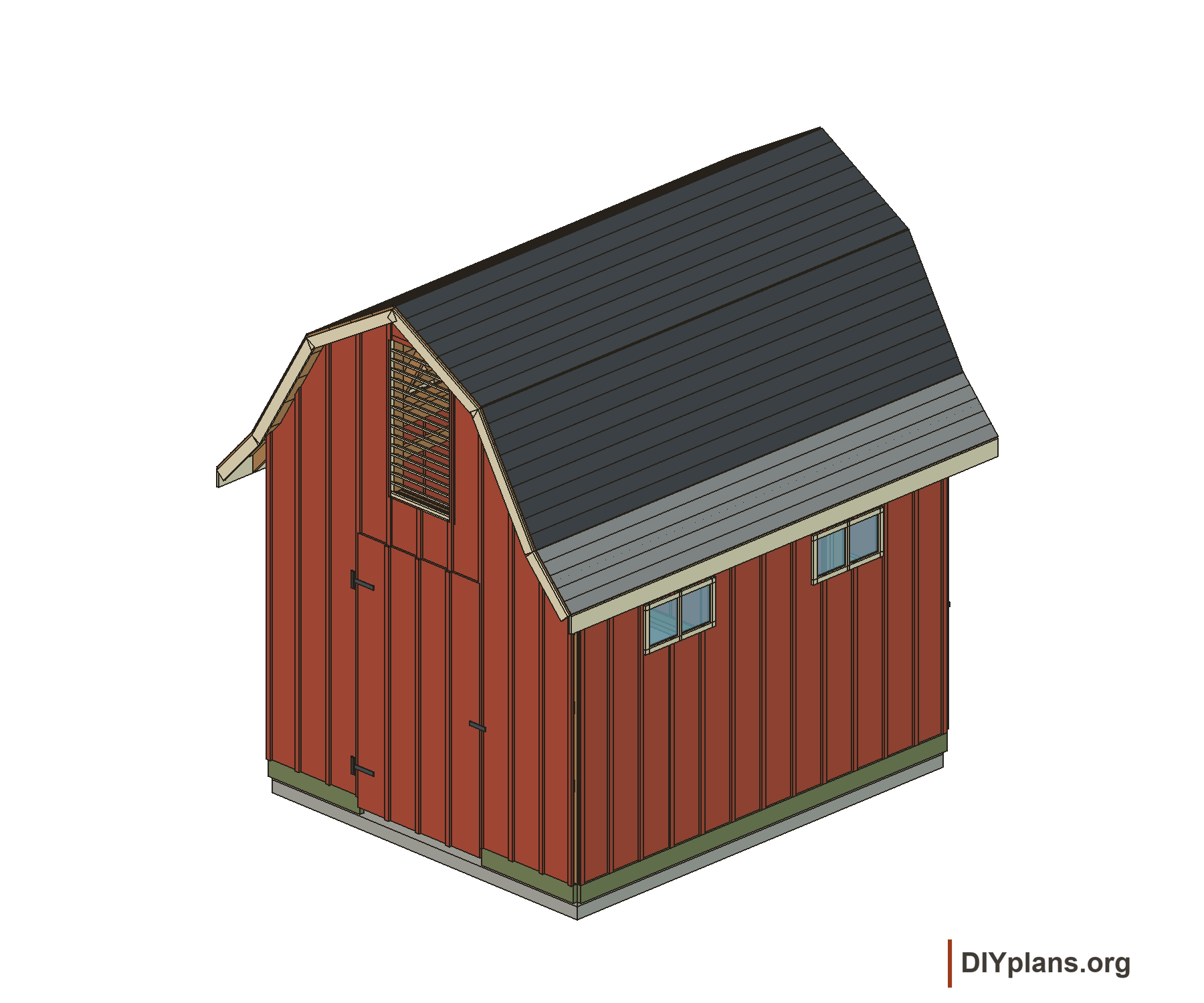
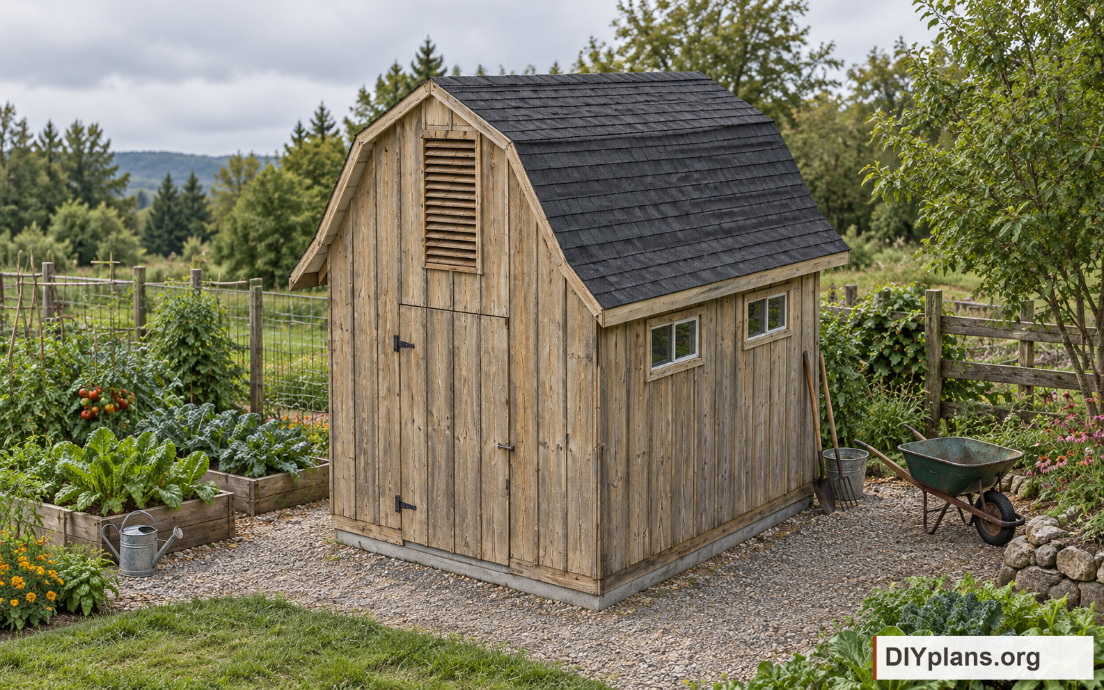
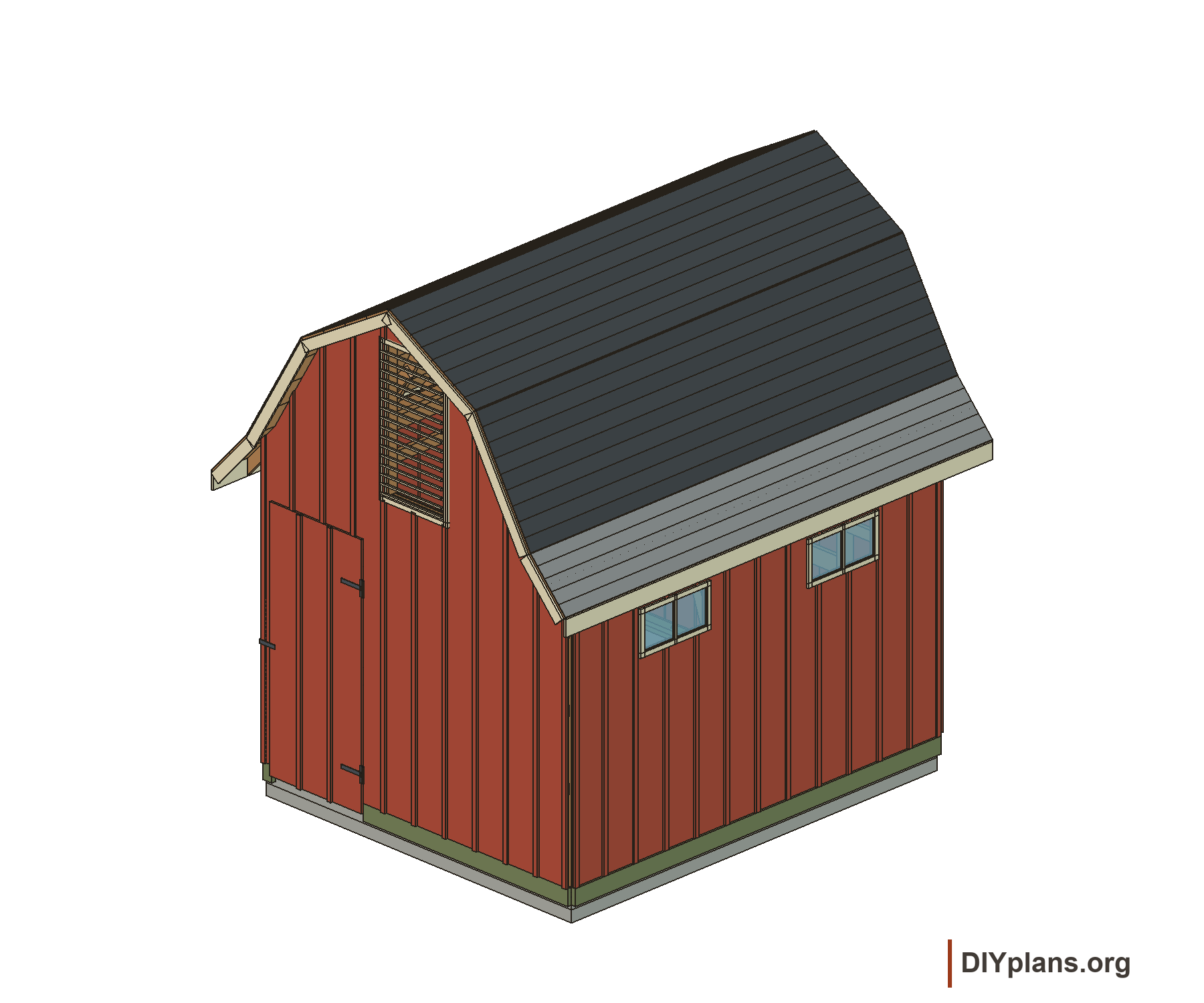
Before you start
- The foundation edge is modeled as 12 in wide and 8 in total depth, with a 4 in slab field. Soil, frost, wind/snow loads and foundation capacity have not been assessed.
- This work reconciles the plan geometry. Member capacity and connection fastening have not been certified for a building site.
- Roof planks are 14 ft long and nominal 1 in thick. Board widths, paper/shingle thicknesses and shingle course layout are chosen visualization dimensions. The design plywood alternatives are recorded separately.
- Door offsets, window/louver positions, board joints and hardware sizes that the sheet does not specify use the documented model layout. Glazing beads, anchors, nuts and hinges are simplified; individual nails, screws and threads are omitted.
- The design BOM is a purchasing schedule. Stock counts, concrete allowance, mesh area and sheathing allowance are kept separate from modeled quantities. The small nail-weight text remains marked uncertain.
- The lettered cut list covers A-E only. The material allowance is a preserved purchasing transcription, not a stock-nesting or consumption reconciliation for all modeled parts.
- This is a drawing reconstruction with simplified joinery and hardware. The sections below describe the preserved model; they do not add a completed construction fastening schedule.
Dimensions and opening sizes
- Outside framing width
- 120 in
- Outside framing length
- 144 in
- Roof bearing elevationAbove slab top
- 96 in
- Framing ridge elevationRoof finishes above this datum
- 163 11/16 in
- Front door nominal opening width
- 48 in
- Rear door nominal opening width
- 36 in
Shopping & cut lists
Get the shopping and cut lists
Includes all available CAD files, shopping lists and cut lists for every configuration of this plan. One payment, $19 USD.
Get the plan package · $19Secure checkout with Stripe. Your account is created after payment.
Already purchased? Sign in to access your plans.
Tools & equipment
- FreeCAD or a STEP viewer for examining the model
- Measurement and section tools in the CAD viewer
BEFORE YOU BUILD
Use this work at your own risk
No person or organization makes any guarantee or warranty, express or implied, regarding this design, its documentation, digital files, or website views. They are not professional services and do not create an architect-client or other professional-client relationship. No promise is made about accuracy, completeness, reliability, code compliance, or fitness for your project.
Buildings and building projects are complex, and many things can go wrong. You are responsible for checking dimensions and site conditions, choosing suitable materials and methods, obtaining permits, following codes and manufacturer instructions, and getting qualified professional help when needed. To the fullest extent permitted by law, DIYPlans.org disclaims liability for damages resulting from use of this work. Read the FAQ about your responsibilities.
Instructions
01 Foundation
- 10 ft x 12 ft. Resolved as nominal outside framing, 120 x144 in.
- 4 in concrete slab; thickened edge drawn. 4 in field; modeled approximation 12 in wide and 8 in deep edge flagged.
- 6 x 6 in 10/10 WWF; 180 sq ft. Grid modeled, hidden inside slab; purchasing area retained separately.
- 12 anchors, 5/8 x 9 in. 12 plain shanks with schematic nuts; locations inferred.
Check: Foundation
02 Wall framing
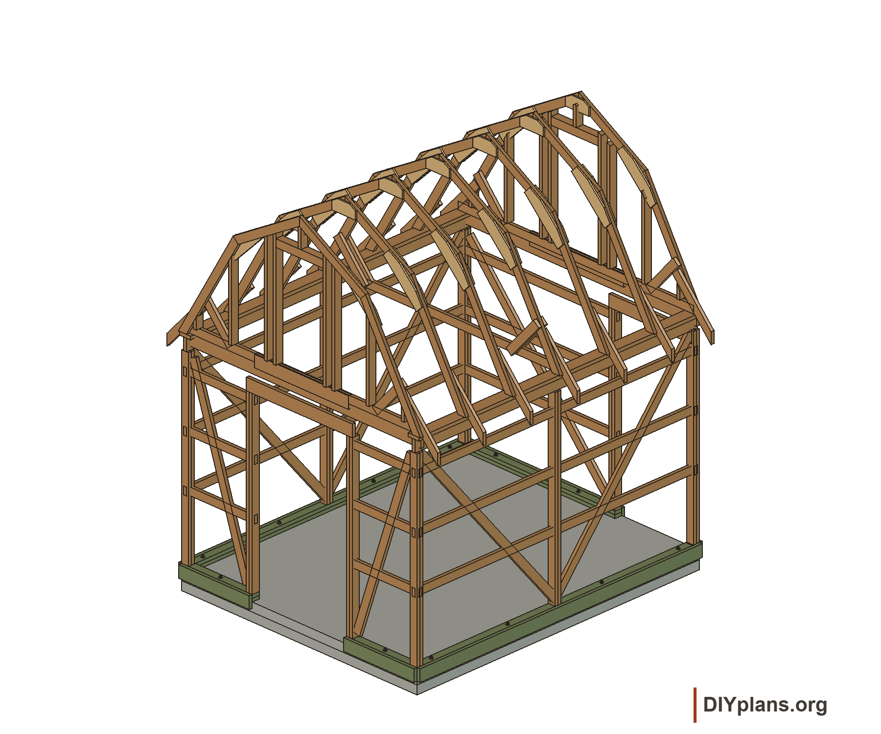
- Two 2x4 sills, cold-soak or pressure treated. Two flat sill layers, cut at doors.
- 2x6 cold-soak or pressure treated. Separate vertical perimeter member.
- Two 2x4 posts, back to back. Six principal double posts plus paired structural door-jamb posts; rear corner post shared.
- 2x4 girts; 2 ft vertical spacings. Girt levels use 24 in intervals; absolute levels inferred.
- 2x6 plates, header, door header. Separate top and door headers; joints simplified.
- 2x4 cross brace. Four side-wall and three end-wall diagonals, separate from door leaf framing.
Check: Wall framing
03 Roof frames
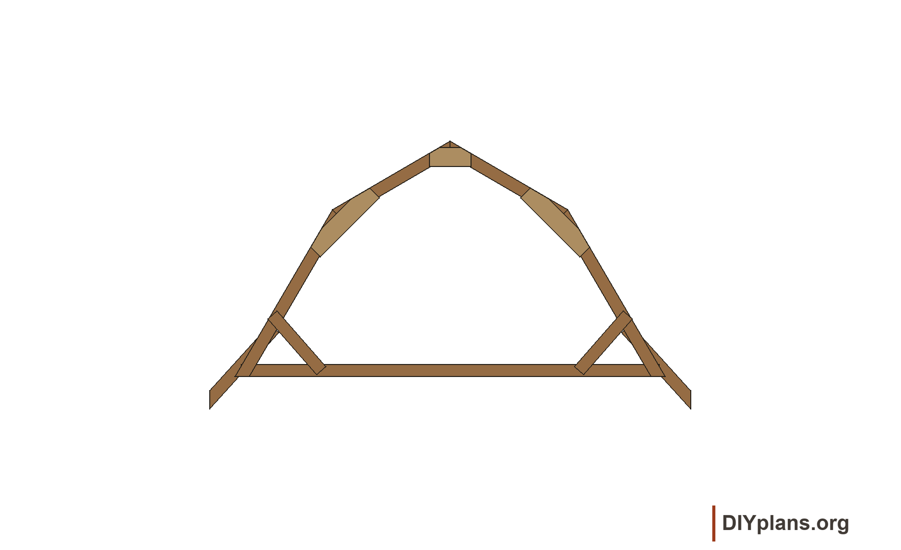
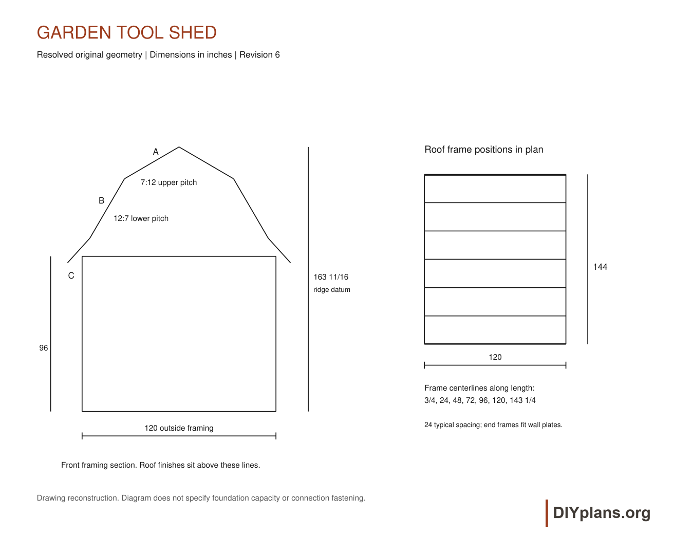
- 2x4 rafters, 24 in OC. 24 in typical spacing; end frames flush to 144 in wall plates; A/B/C grouped per frame.
- 27 1/2 and 34 1/4 in horizontal runs; 48 and 19 1/2 in rises. Resolved lower run 28, upper run 33 3/4 in, upper rise 19 11/16 in; outside arris datum has a real horizontal heel.
- 12:7 lower and 7:12 upper pitch symbols. Exact pitch symbols govern. Approximate section and cut dimensions are superseded by the resolved schedule.
- C eave; 9 in projection; 4 in drop; 15 in upper joint. Solved C 47.828694 degrees; 15 in marks its head; separate roof break from actual B/C intersection.
- Two 1x6 splice plates; one side only at end rafters. 24 D plates and 12 E plates; inward-only end plates.
- 2x4 crosstie at each end and center. Exactly 3 ties at stations 0, 72, 144.
- 2x4 brace; one on end rafters, two on middle; 23 in run, 19 1/2 in rise. 8 mirrored brace pieces across 3 tied frames; ends fitted approximately.
- Two 16d nails, toenail each rafter. Installation note retained; individual nails not represented.
- 8 ft height. 96 in slab-to-tie underside/bearing datum.
Check: Roof frames
04 Resolved master patterns / installed roof frames
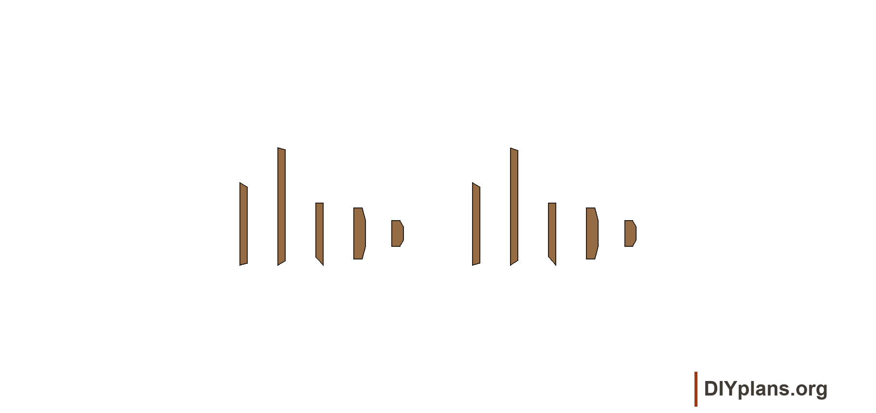
- 2x4 piece A; cuts in design comparison. Resolved: 39 1/16 in long; 36 1/8 in short/flat nose; profile is congruent to installed parts.
- 2x4 piece B; cuts in design comparison. Resolved: 55 9/16 in long; 52 5/8 in short/flat nose; profile is congruent to installed parts.
- 2x4 piece C; cuts in design comparison. Resolved: 29 1/2 in long; 25 5/8 in short/flat nose; profile is congruent to installed parts.
- 1x6 piece D; cuts in design comparison. Resolved: 24 in long; 12 in short/flat nose; profile is congruent to installed parts.
- 1x6 piece E; cuts in design comparison. Resolved: 12 in long; 6 in short/flat nose; profile is congruent to installed parts.
Check: Resolved master patterns / installed roof frames
05 Doors
- 3 ft x7 ft and 4 ft x7 ft doors. Opposite END walls; rear door near corner, front door centered; offsets inferred.
- 2x6 door framing. 2x6 door leaf rails and diagonal, plus door header; structural jamb posts are doubled 2x4.
- Two sets of two 8 in T strap hinges with screws. Four 8 in straps; simplified pins; screws retained as design note.
- Two lock hasps with screws. Two schematic hasps.
Check: Doors
06 Windows
- Two 12x12 in fixed panes per unit; 8 panes total. Four two-pane units; two per long wall; pane dimensions exact.
- 64 linear ft quarter-round. Glazing retention strips represented; exact bead section unspecified.
Check: Windows
07 Louvers
- 2 ft x4 ft louver, both ends. Two 24x48 in openings; blade pattern and location inferred.
- 2x6x4 ft header. One 48 in member at each gable.
Check: Louvers
08 Cladding / doors
- Board and batten; 1x12 boards and 1x2 battens. Selected board construction; 12 in board module; dressed lumber modeled approximation.
- 1/2 in exterior plywood, 1x2 strips 12 in OC. Alternative retained as note; not superimposed on board siding.
Check: Cladding / doors
09 Roof finish
- Solid deck 1 in boards, 14 ft long, 12 in overhang. Separate full-length boards with 12 in end overhangs.
- 265 lb asphalt shingles over asphalt building paper. Separate paper and shingle courses; thicknesses schematic.
- 5/8 in plywood sheathing. Alternative retained as note; board decking selected.
- 1x6 trim at eaves. Separate 1x6 fascia, 14 ft long.
- 1x4 trim at 12 in gable overhang. Separate 1x4 rake strips on all roof slopes at both ends.
Check: Roof finish