
BEFORE YOU BUILD
Use this work at your own risk
These files have not been checked for accuracy, safety, structural adequacy, or building-code compliance. They may contain serious errors and are not construction-ready. Obtain independent qualified design and review before building.
No person or organization makes any guarantee or warranty, express or implied, regarding this design, its documentation, digital files, or website views. They are not professional services and do not create an architect-client or other professional-client relationship. No promise is made about accuracy, completeness, reliability, code compliance, or fitness for your project.
Buildings and building projects are complex, and many things can go wrong. You are responsible for checking dimensions and site conditions, choosing suitable materials and methods, obtaining permits, following codes and manufacturer instructions, and getting qualified professional help when needed. To the fullest extent permitted by law, DIYPlans.org disclaims liability for damages resulting from use of this work. Read the FAQ about your responsibilities.
Instructions
Step 1 Read the four-sided base
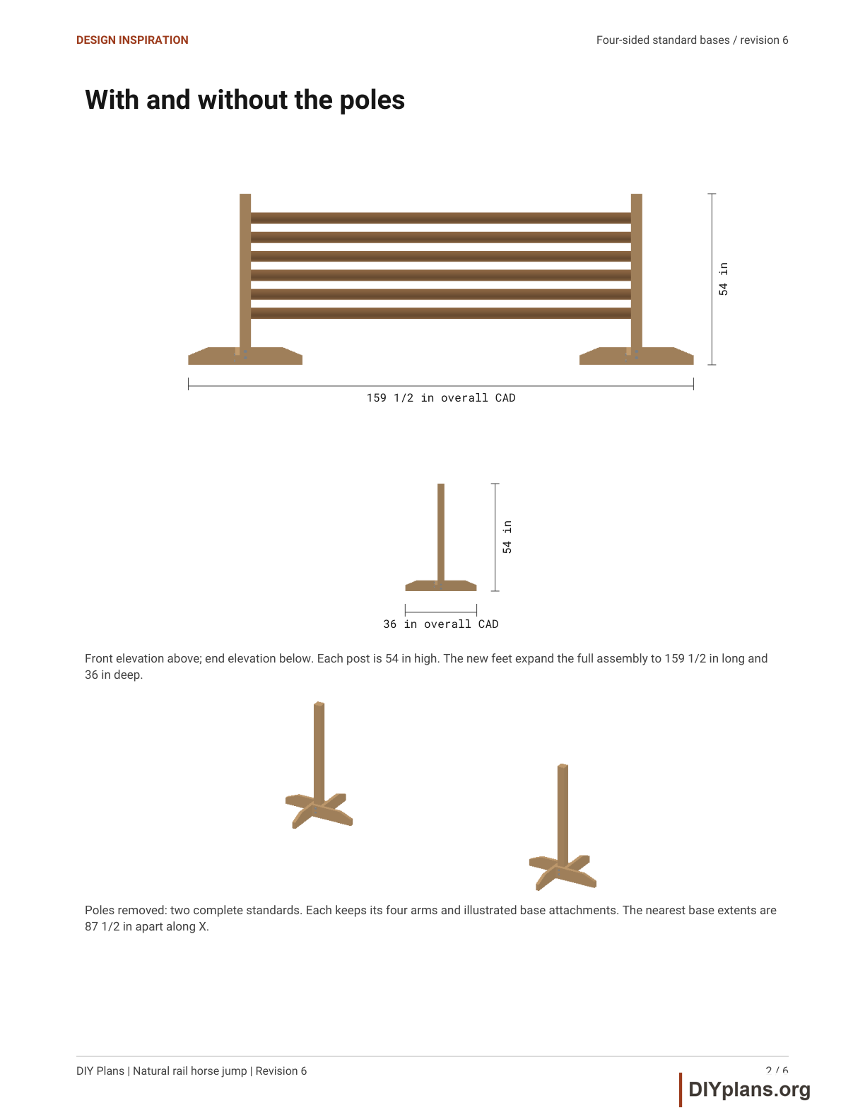
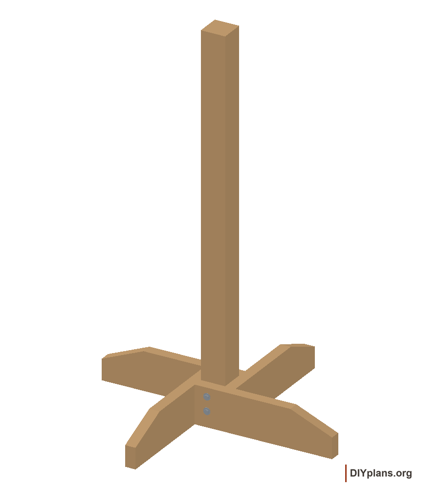
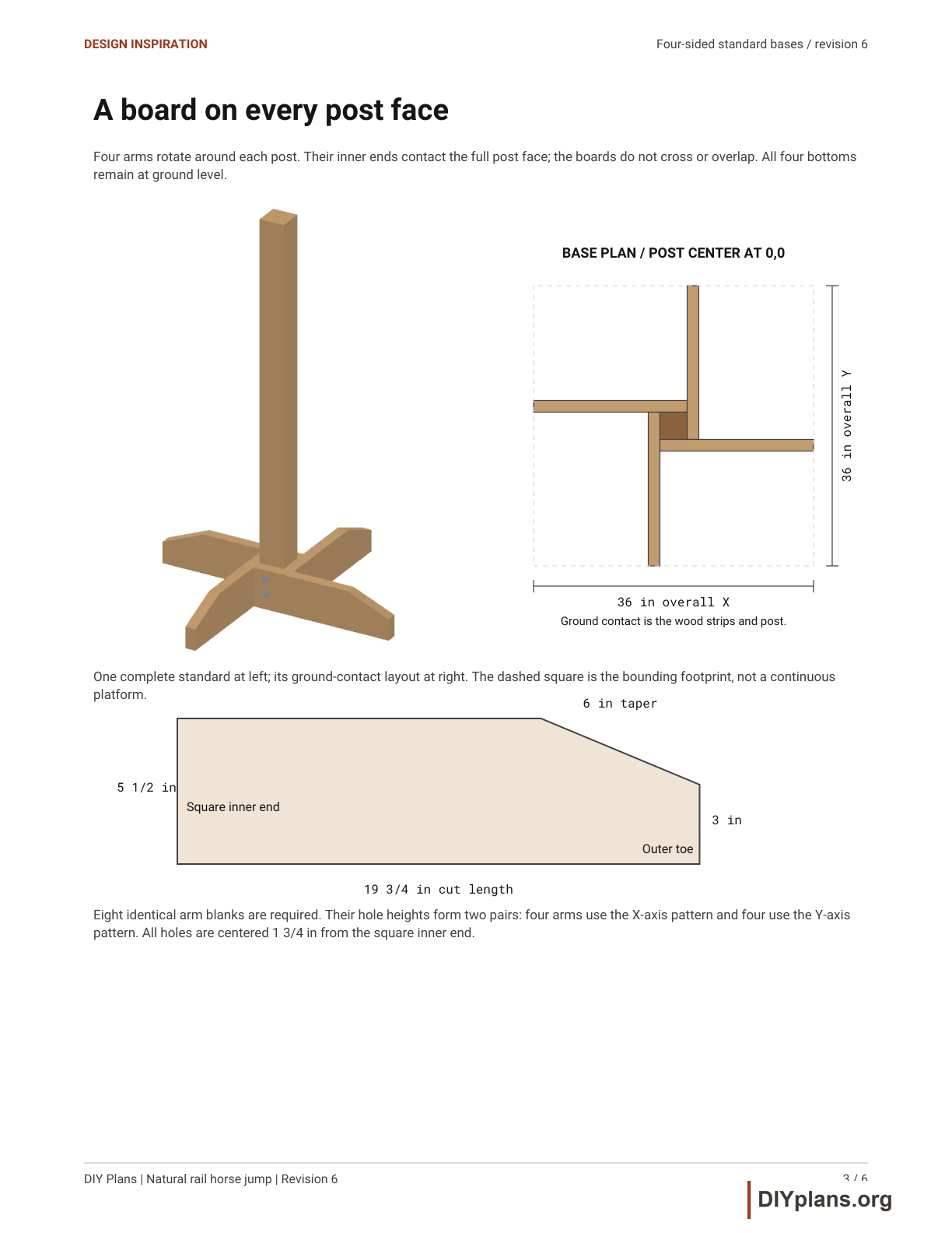
- Each standard has one 19 3/4 in arm on each of its four faces. The arms rotate around the post in a pinwheel, giving a 36 x 36 in bounding footprint without crossing boards. All arm bottoms and the post base share the ground plane.
Check: Find four arms on each standard, with support extending in both horizontal directions.
Step 2 See the standards without poles
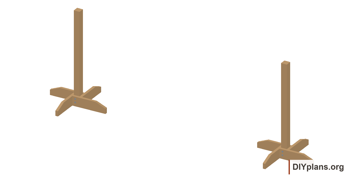
- The poles-removed view shows both complete standards. Their four-arm bases and depicted through-bolt attachments are unchanged by pole removal. Ground contact is the four narrow arm strips and post, not a solid square platform.
Check: Identify the clear gap between the two independent bases and the flat contact beneath every arm.
Step 3 Inspect the illustrated base connections
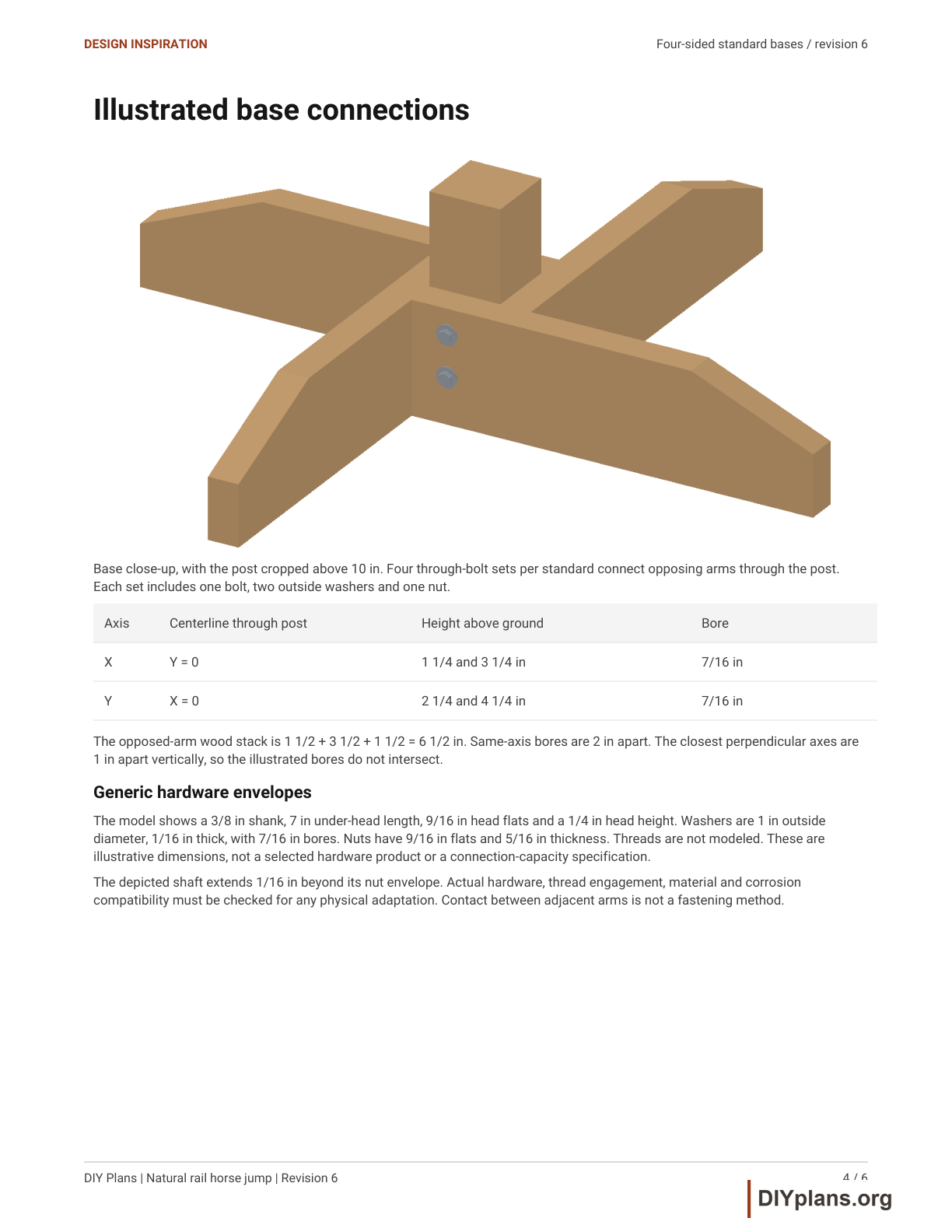
- Each standard has four bolt sets. The X-directed axes are 1 1/4 and 3 1/4 in above ground; the Y-directed axes are 2 1/4 and 4 1/4 in above ground. Each axis passes through two opposed arms and the post, a 6 1/2 in wood stack.
Check: Locate two bores in each arm and check that the perpendicular bore pairs sit at different heights.
Step 4 Compare the rail positions
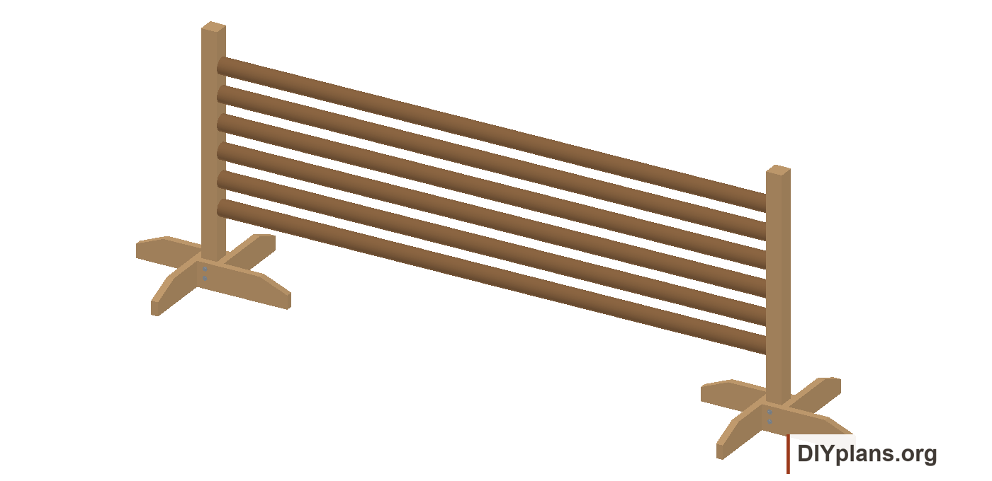
- The six 120 in pole bodies have tops at 18, 24, 30, 36, 42 and 48 in. The drawings show uniform 3 1/2 in poles within the 3-4 in natural-pole range. Pole ends, post slots and release hardware are not modeled.
Check: The six rail positions are identified; their end connections remain unspecified.
Step 5 Explore a separate variation
- Use the native CAD to study proportions, finishes or base details. Individual solids are editable; the dimension sheet is informational. Update drawings and quantities together if you change the geometry.
Check: Save a separate copy and record the dimensions changed.