BEFORE YOU BUILD
Use this work at your own risk
These files have not been checked for accuracy, safety, structural adequacy, or building-code compliance. They may contain serious errors and are not construction-ready. Obtain independent qualified design and review before building.
No person or organization makes any guarantee or warranty, express or implied, regarding this design, its documentation, digital files, or website views. They are not professional services and do not create an architect-client or other professional-client relationship. No promise is made about accuracy, completeness, reliability, code compliance, or fitness for your project.
Buildings and building projects are complex, and many things can go wrong. You are responsible for checking dimensions and site conditions, choosing suitable materials and methods, obtaining permits, following codes and manufacturer instructions, and getting qualified professional help when needed. To the fullest extent permitted by law, DIYPlans.org disclaims liability for damages resulting from use of this work. Read the FAQ about your responsibilities.
Instructions
Step 1 Sort the pair’s stock
- Choose straight boards without splits, loose knots or wane where the cuts and screws will land. Check the sections against the cut list before laying out the parts.
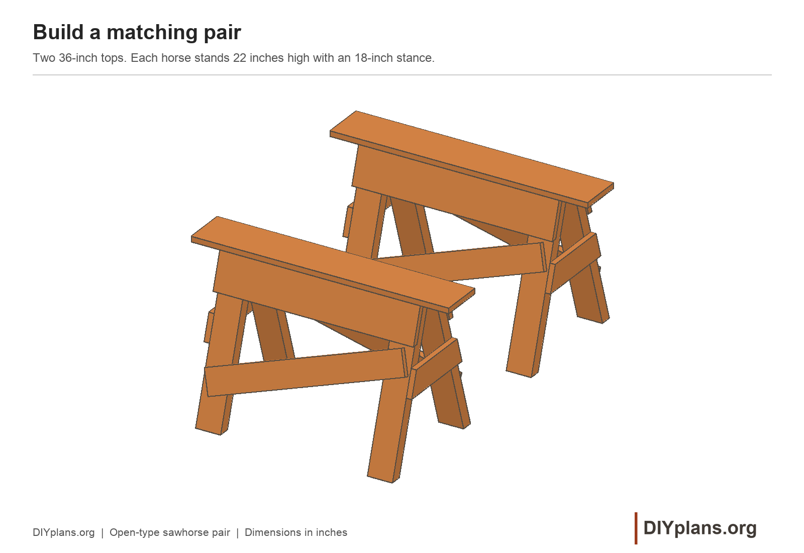
- Mark parts for Horse A and Horse B. Each horse needs one cap, two aprons, two top blocks, four legs, two end ties and two diagonals.
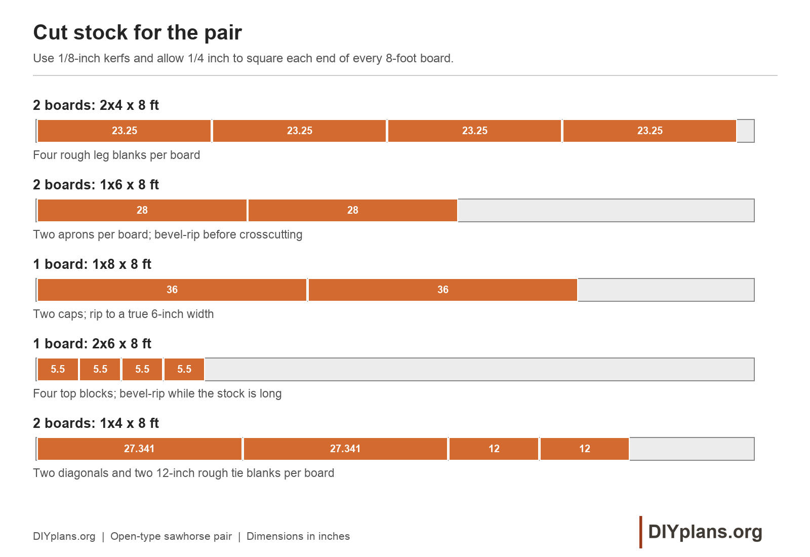
- Reserve four 23 1/4-in rough leg blanks per 2×4. Reserve two 28-in aprons per 1×6, two 36-in caps from the 1×8, and four 5 1/2-in blocks from the 2×6.
- Mark two 27 5/16-in diagonals and two 12-in rough tie blanks on each 1×4. Leave 1/8 in. for each separating cut and 1/4 in. at both stock ends.
Check: Both horses have a complete set of marked parts, with kerf and end-trim space left between cuts.
Step 2 Cut eight matching legs
- Crosscut eight 23 1/4-in rough blanks from the two 2×4s.
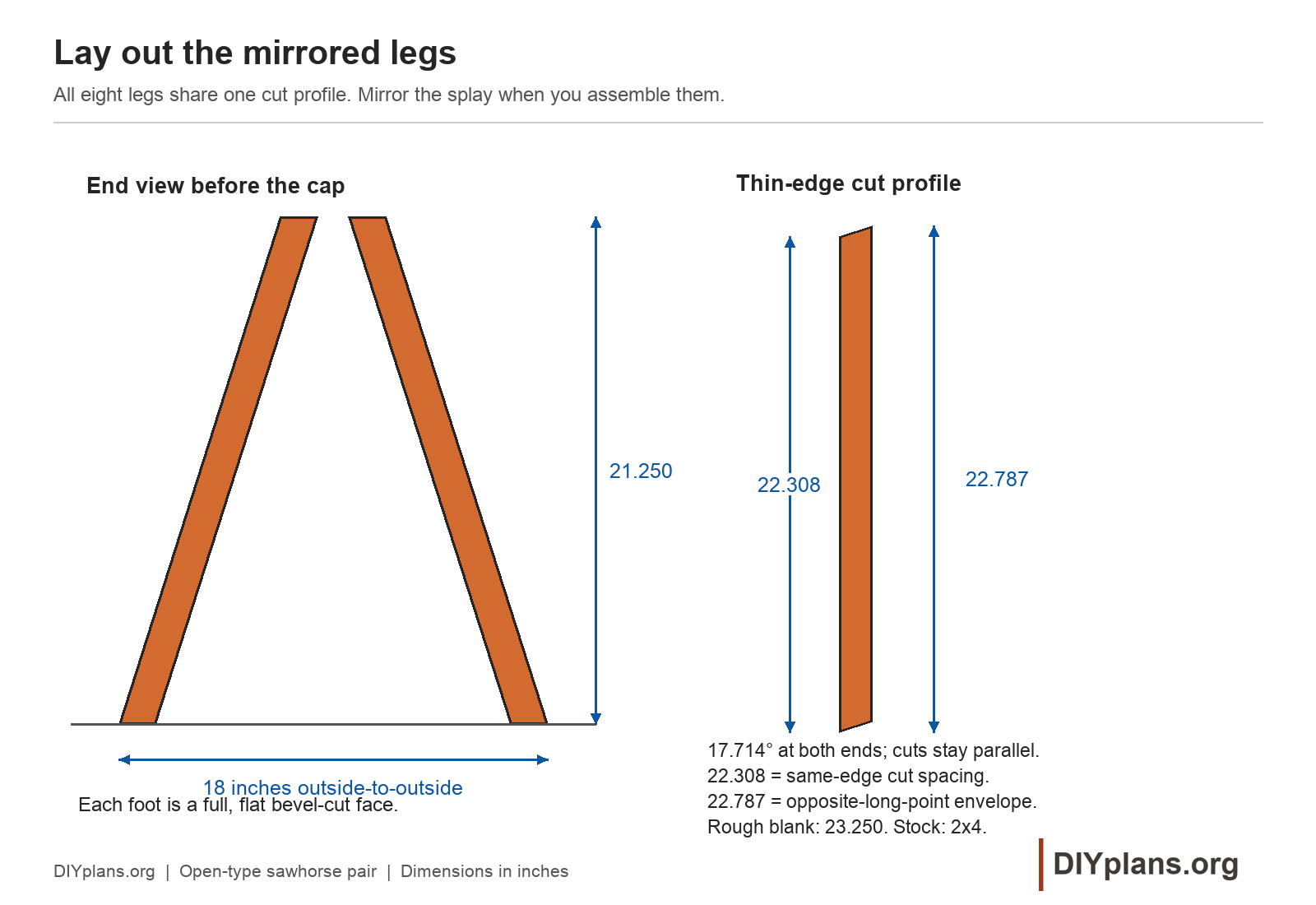
- Set the saw miter to zero and bevel to 17.714° from square. Make a trial cut in offcut stock and compare it with the dimensioned leg profile.
- Cut both ends of each leg parallel. Keep 22 5/16 in. between the two cuts along the same long edge of a broad face. The envelope between opposite long points is 22 13/16 in.; do not use that number as the same-edge length.
- Stack the finished legs against one reference stop and compare both cut faces. Label the near and far sets so they lean outward in opposite directions, with flat feet and level upper ends.
Check: Eight equal legs match the same profile. Their end faces are parallel, and the near and far sets mirror across the horse.
Step 3 Shape the top members
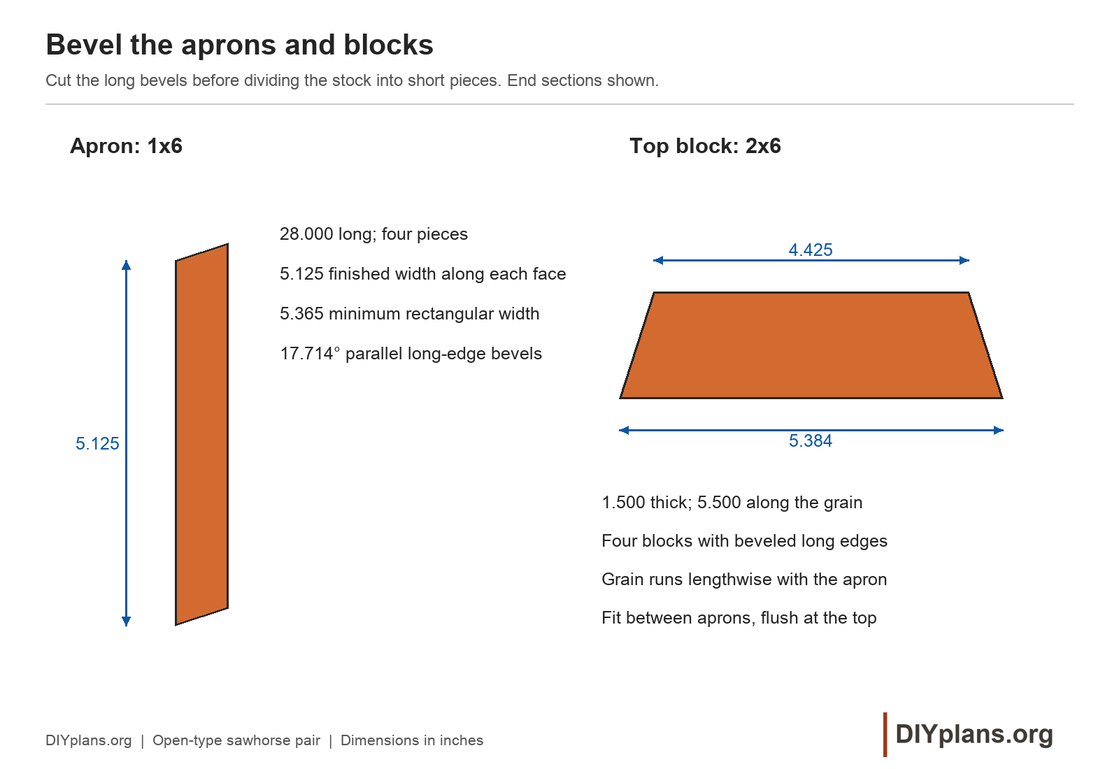
- Bevel both long edges of each 1×6 in the same direction at 17.714°. Finish each broad face 5 1/8 in. wide; the profile spans 5 3/8 in. between opposite edge tips. Crosscut four aprons to 28 in.
- Bevel-rip the long 2×6 with opposite 17.714° edge bevels. Make its lower face 5 3/8 in. wide and upper face 4 7/16 in. wide, keeping the full 1 1/2-in thickness.
- Keep the stock long and supported for these rip cuts. Use the saw’s guard and riving knife where the setup allows, and use suitable push blocks. Do not hold a short top block by hand against the blade.
- Crosscut four 5 1/2-in top blocks after ripping. The grain runs along each block’s 5 1/2-in length. Rip the 1×8 to 6 in. and crosscut two 36-in caps; leave their edges square and their thickness at 3/4 in.
Check: Four matching aprons, four matching trapezoidal blocks and two 36 × 6 × 3/4-in caps match the profiles.
Step 4 Fasten each top frame
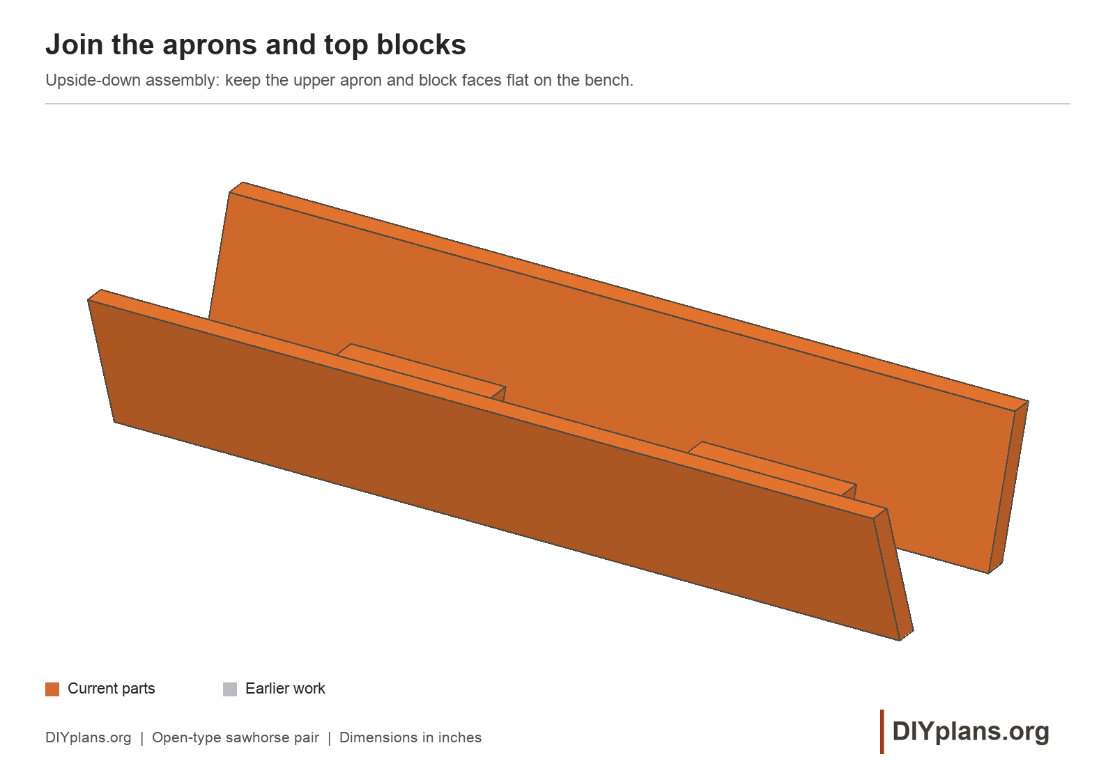
- Lay two aprons upside down on a flat bench with their top edges 6 in. apart. Fit two blocks between them, with each narrow block face against the bench.
- Measure from the left end of the aprons. Position the blocks from 5 to 10 1/2 in. and from 17 1/2 to 23 in. Clamp the top edges and block faces flat to the bench.
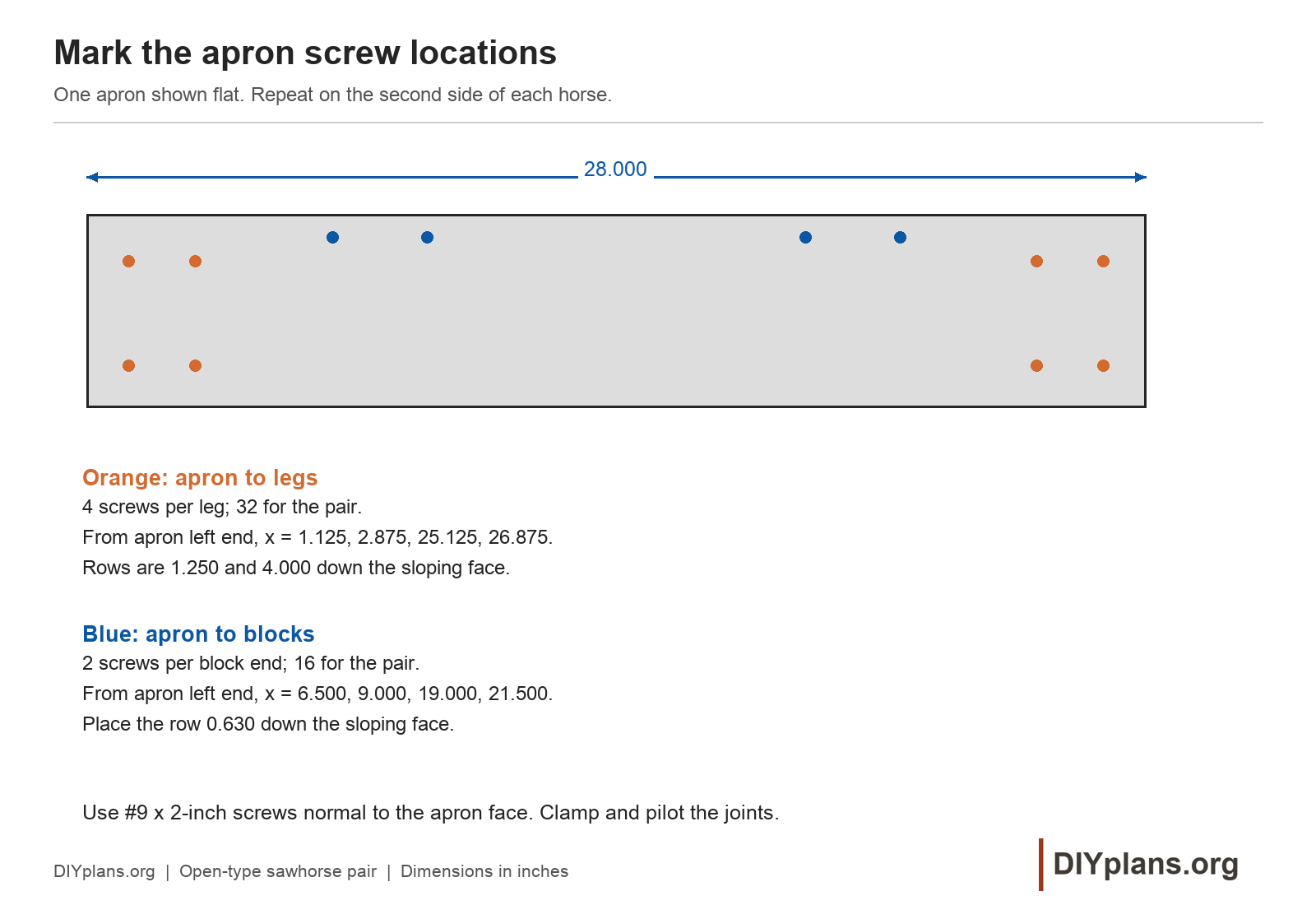
- Mark two screws per apron-to-block joint. Place the screw columns 6 1/2, 9, 19 and 21 1/2 in. from the apron’s left end, and 5/8 in. down its outside face from the top edge.
- Drive eight #9 × 2-in GRK R4 screws per frame, normal to the sloping apron face. Seat the heads flush. Build the second frame to the same layout.
Check: Each frame is 28 in. long, measures 6 in. across its top edges, and sits flat on the bench.
Step 5 Attach the four legs
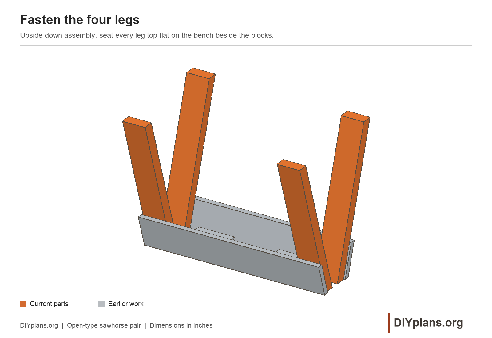
- Keep the top frame upside down. Seat the four leg tops against the bench inside the aprons, with the feet flaring outward across the horse’s width.
- Set each leg’s nearer edge 1/4 in. from the corresponding apron end. The leg centerlines are 2 and 26 in. from the apron’s left end. Keep the leg faces tight to the apron faces.
- Mark four screws at each apron-to-leg joint. Space the columns 1 3/4 in. apart, centered on the leg; place the rows 1 1/4 and 4 in. down the apron face from its top edge.
- Drive the 16 #9 × 2-in screws per horse normal to the apron face. Clamp or support the assembly until both kinds of bracing are installed. Repeat for the second horse.
Check: All four upper leg faces meet the same plane as the frame top, and each leg is tight against its apron.
Step 6 Fit the end ties
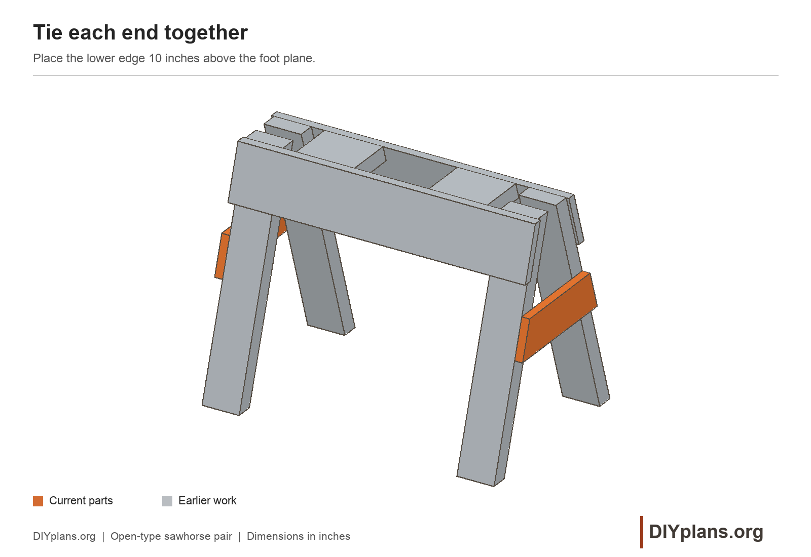
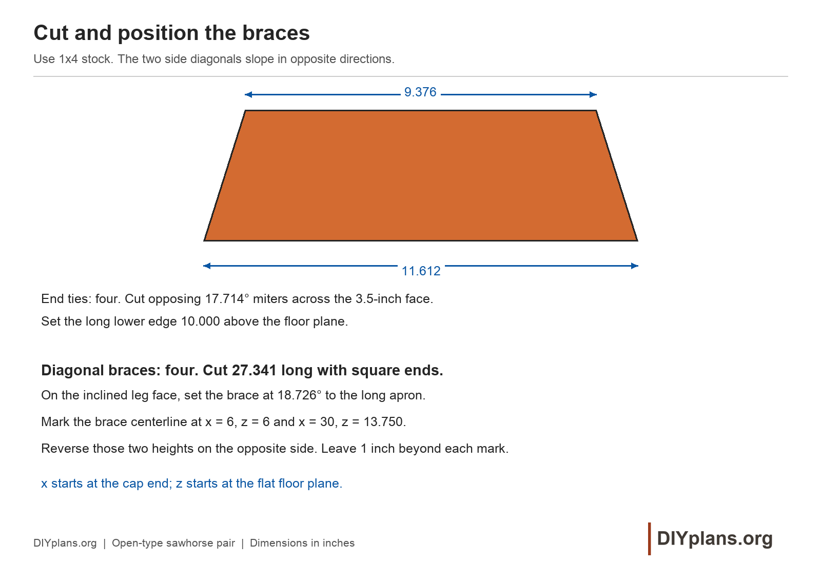
- Finish the four rough tie blanks with opposite 17.714° miter cuts across the 3 1/2-in face. Keep the saw bevel at zero. Each tie has an 11 5/8-in bottom edge and a 9 3/8-in top edge.
- Stand each supported horse on a flat, level surface. Set the outer foot-to-foot spread to 18 in. and keep both top aprons level. Clamp one tie across the leg edges at each end of the horse, with its long edge 10 in. above the floor.
- Mark two screws into each leg. Place the rows 7/8 and 2 5/8 in. above the tie’s bottom edge, each 13/16 in. inward horizontally from the adjacent sloping tie end.
- Drive four #9 × 2-in screws through each tie into the legs, square to the tie face. Use eight per horse and repeat on the second horse.
Check: The tie bottoms are 10 in. above the same floor datum, and both end pairs retain an 18-in stance.
Step 7 Brace the long sides
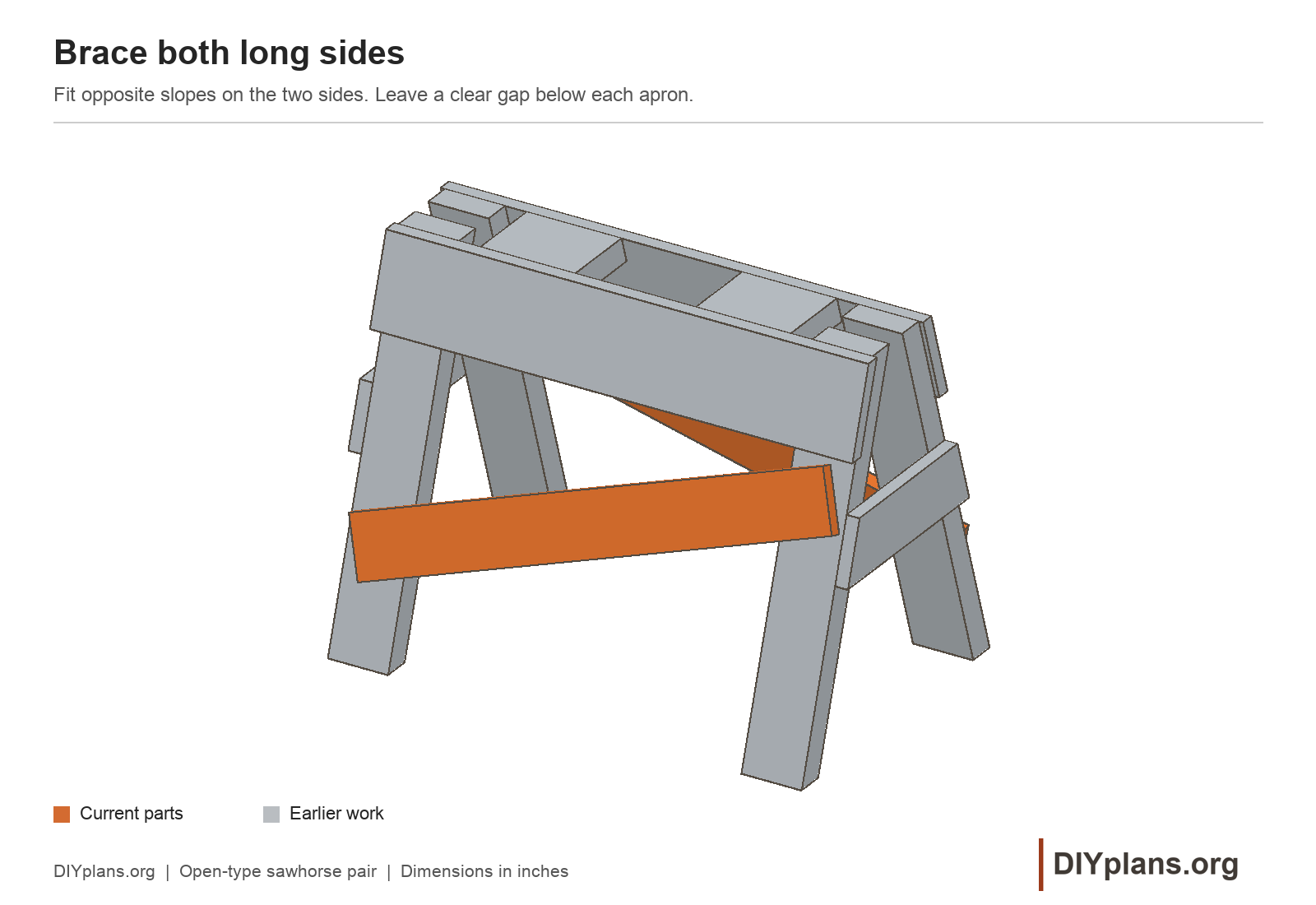
- Crosscut four 1×4 diagonals to 27 5/16 in. with square ends. The 18.726° angle is the brace’s installed angle on the sloping leg face, not a saw setting.
- On the near side, mark the left leg centerline 6 in. above the floor and the right centerline 13 3/4 in. above the floor. Connect these marks along the diagonal’s centerline and leave 1 in. of brace beyond each mark.
- Reverse the slope on the far side, from 13 3/4 in. at the left leg to 6 in. at the right. Clamp both braces tight to the leg faces, with space between each high brace end and the apron.
- At each marked leg centerline, place two screws 3/4 in. vertically above and below the mark. Drive eight #9 × 2-in screws per horse, normal to the brace faces. Repeat the layout on the other horse.
Check: Each horse has two diagonals with opposite slopes. All brace ends clear the aprons and all four feet remain on the floor.
Step 8 Attach the replaceable caps
Play animationStop animation
 Loading image
 Loading image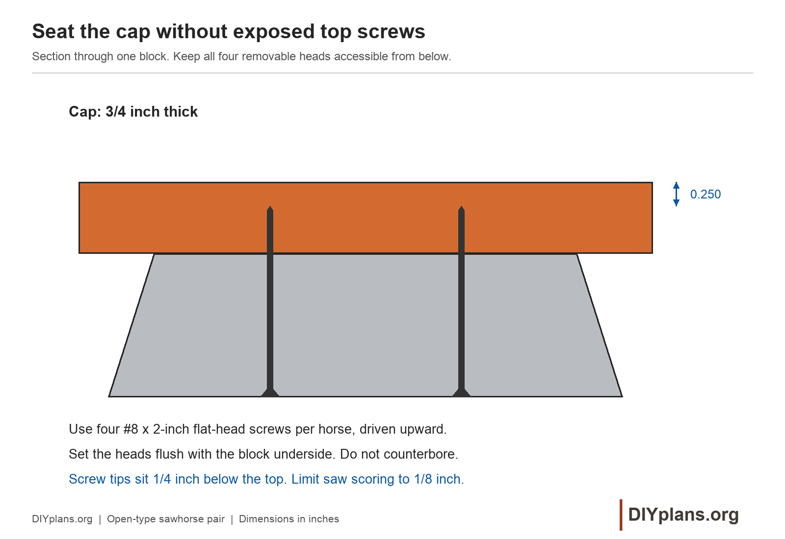
- Set a cap on each frame with 4 in. of overhang beyond each apron end. Align the 6-in cap width with the top apron edges and clamp it in place.
- Mark two holes through each top block, centered along its 5 1/2-in length and 1 in. to either side of the cap centerline. Drill 3/16-in clearance holes through the blocks and shallow seats for flush flat heads.
- Transfer those centers to the cap underside. Drill 3/32-in softwood pilot holes no deeper than 1/2 in., using a positive depth stop. Keep the pilot and screw paths vertical.
- Drive four #8 × 2-in flat-head screws upward through the blocks into each cap. Stop with each head flush with the block underside; do not bury it. Use eight screws for the pair.
Check: Each cap is secure, has equal 4-in end overhangs, and has no fastener heads on its working face.
Step 9 Check the feet and height
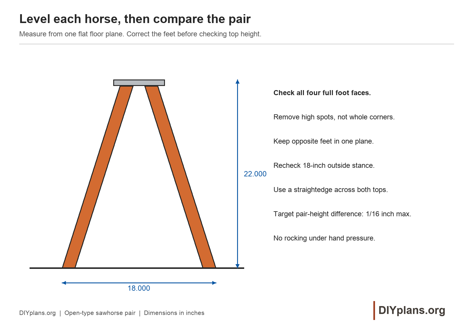
- Set each horse on the same flat, level reference surface. Check the top at both ends and press lightly at each corner to find rocking.
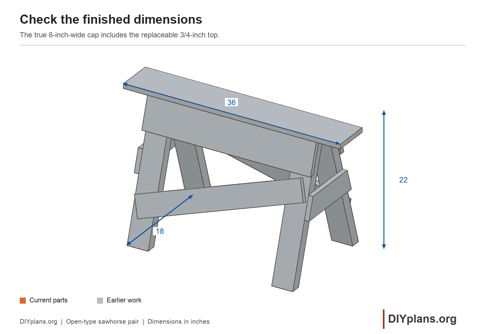
- Measure 22 in. from the reference surface to the cap top and 18 in. across the outside foot edges. Confirm that all four foot faces touch the surface.
- Correct an assembly skew or an uneven cut before removing wood from a foot. If a leg needs recutting, replace it to the common profile and recheck the pair; shortening one horse changes its finished height.
- Run a straightedge over each cap and inspect every joint for a gap, split or protruding screw. Ease sharp edges without rounding away the foot contact faces.
Check: Each horse stands without rocking, its cap is level at 22 in., and its stance measures 18 in.
Step 10 Match and inspect the pair
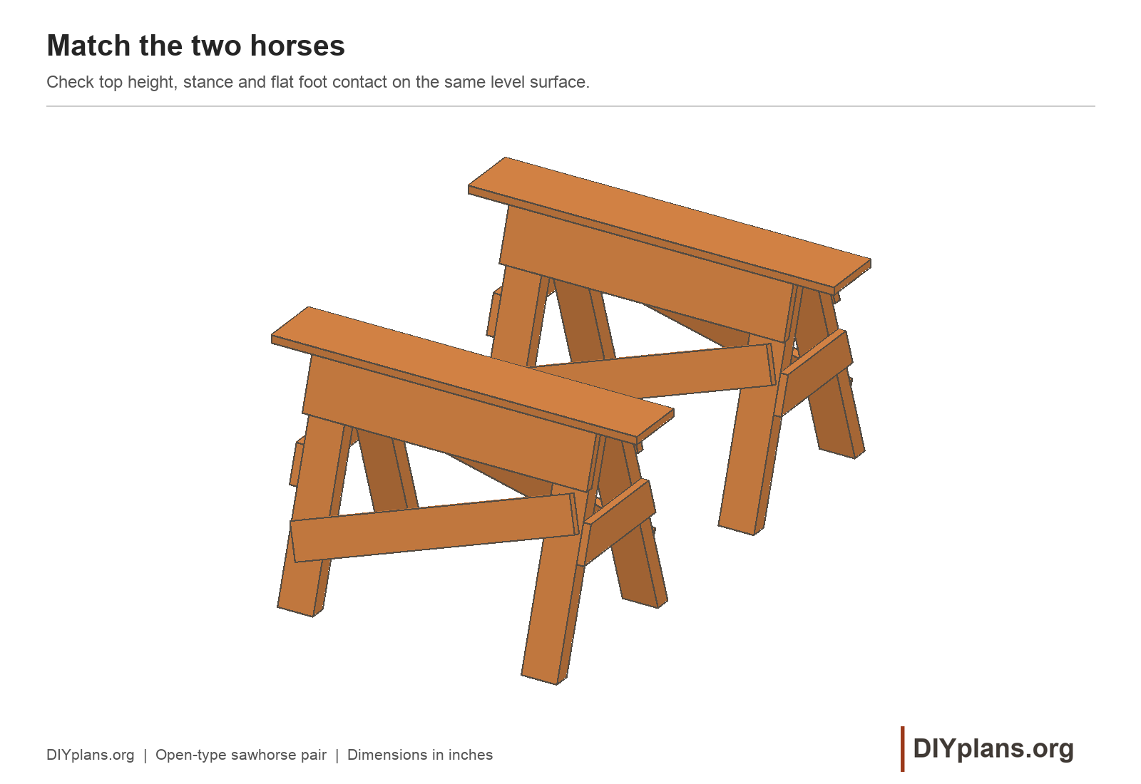
- Place the horses on the same level surface with their caps parallel. Lay a straight board across both caps and check that it contacts both without twist.
- Compare the 36-in top lengths, 6-in top widths and 22-in heights. Confirm the same leg positions, opposite diagonal slopes and 18-in stance on both horses.
- Try the clamps you intend to use at the clear cap ends. Keep clamp jaws and tool paths clear of the braces and hidden screws.
- Use separate spacers when cutting through a workpiece. Limit any scoring of the cap to 1/8 in. and replace it before a groove exceeds 1/8 in. A new cap has only 1/4 in. of wood above its hidden screw tips; never saw through it.
Check: The pair has matching, level working faces and four-foot contact on both horses. Clamps fit without striking a brace or fastener.
Step 11 Replace a worn cap
- Replace a cap before any groove exceeds 1/8 in., or sooner if it splits or loosens. Remove the workpiece and support the horse securely. Back out the four screws beneath the top blocks and lift off the cap.
- Cut a new cap to 36 × 6 × 3/4 in. from sound, flat stock. Keep the original thickness so the pair remains 22 in. high.
- Transfer the hole positions and drill the same stopped pilots. Refit the cap with four sound #8 × 2-in screws, stopping flush at the block undersides.
- Recheck top height, four-foot contact and alignment with the other horse. Replace a split or loose component before using the pair.
Check: The replacement cap is secure and the two working faces still match.
Sources
Original DIYplans.org adaptation of the 36 x 22 x 18-inch open-type sawhorse concept identified in NDSU ND 72-2-2. The historical drawing is not included.