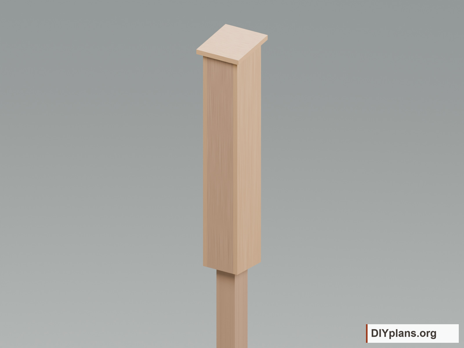
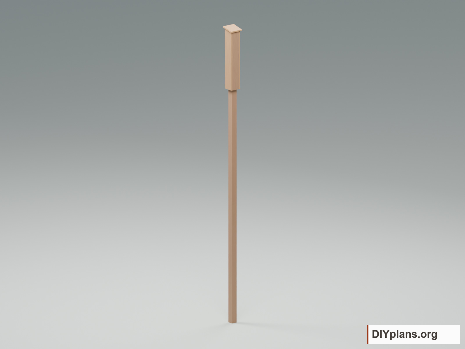
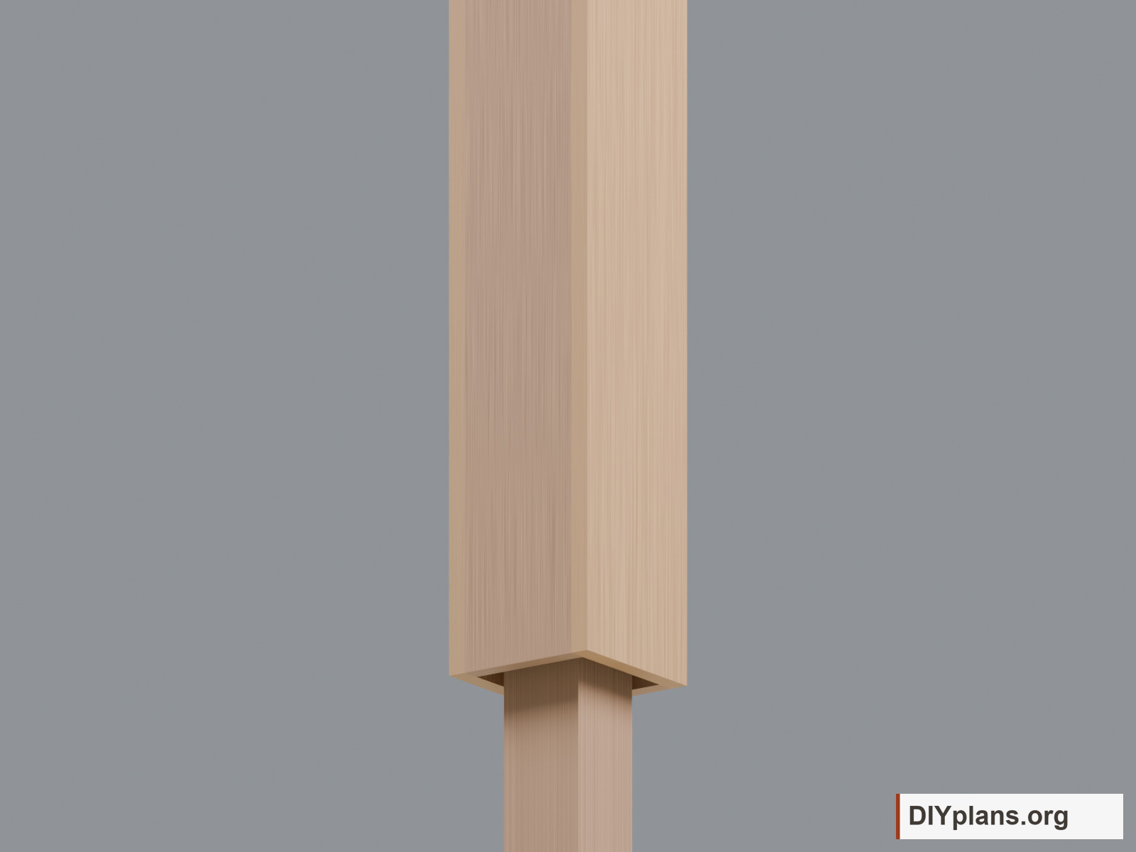
Before you start
- Read the complete cut list and dry-fit the assembly before fastening. Wear eye and hearing protection and control wood dust.
- Use untreated wood with rough roosting surfaces. Leave interiors and exposed landing surfaces unpainted; do not add plastic mesh.
- Choose exterior water-based finish shade for the local summer climate. Provide shade or a suitable alternative roost where overheating is possible.
- Plan at least 12 ft of clear space below the entrance and a clear flight path. Confirm access, mounting support and maintenance access before building.
Dimensions and opening sizes
- Outside shell width and depth
- 6 1/2 in
- Shell low height
- 36 in
- Roost gap
- 3/4 in
- Entrance above modeled ground
- 12 ft
Shopping list
| Buy | Material | Stock size |
|---|---|---|
| 1 piece | Untreated naturally durable cedar post | 4x4 x18 ft actual 3 1/2 square |
| 1 piece | Untreated cedar | 1x6 x8 ft |
| 1 piece | Untreated cedar | 1x8 x8 ft |
| 1 piece | Untreated cedar | 1x10 x2 ft |
| 1 piece | Exterior screws | No.8 x1 5/8 in, box50 |
| 1 piece | Exterior screws | No.8 x1 3/4 in, box25 |
| 4 pieces | Corrosion-resistant lag screws with washers | 1/4 x3 in |
| 1 piece | Exterior paintable sealant | 10 oz cartridge |
| 1 piece | Exterior water-based primer and finish | 1 quart finish plus primer per label |
| 1 piece | Corrosion-resistant roof flashing | 10 x10 in blank |
Quantity notes
One complete configuration, with stock allocation and allowance for saw kerf. Unused stock remains for other projects.
- Untreated naturally durable cedar post, 4x4 x18 ft actual 3 1/2 square: Special-order straight stock; structural support approval required before purchase. Do not splice shorter stock.
- Untreated cedar, 1x6 x8 ft: Rip 5 wide; cut front/back 37 1/2 blanks then bevel to dimensions. Use offcuts for spacers.
- Untreated cedar, 1x8 x8 ft: Rip 6 1/2 wide; two 37 1/2 blanks then slope to 36/37 5/16.
- Untreated cedar, 1x10 x2 ft: Rip 8 across; cut 8 3/16 along slope with end bevels.
- Corrosion-resistant lag screws with washers, 1/4 x3 in: Front/back screws are staggered vertically;1 1/2 in penetration into post.
- Exterior water-based primer and finish, 1 quart finish plus primer per label: No chemical treatment or coating on roosting wood.
- Corrosion-resistant roof flashing, 10 x10 in blank: Form to roof with drip edges; protect sharp edges.
Required installation supplies
- Have a competent local installer verify the 18 ft post, wind resistance, soil/frost conditions, foundation, raising equipment and long-term untreated ground-contact durability before purchase and installation.
- Obtain site-specific footing and temporary support supplies from that design. No footing quantity or structural capacity is implied.
Tools & equipment
- Saw with rip guide and bevel adjustment
- Drill, bits, countersink and screw driver
- Tape measure, square, clamps and 3/4 in spacing gauge
- Rasp or coarse scraper; eye, hearing and dust protection
- Site-appropriate access and lifting equipment
BEFORE YOU BUILD
Use this work at your own risk
No person or organization makes any guarantee or warranty, express or implied, regarding this design, its documentation, digital files, or website views. They are not professional services and do not create an architect-client or other professional-client relationship. No promise is made about accuracy, completeness, reliability, code compliance, or fitness for your project.
Buildings and building projects are complex, and many things can go wrong. You are responsible for checking dimensions and site conditions, choosing suitable materials and methods, obtaining permits, following codes and manufacturer instructions, and getting qualified professional help when needed. To the fullest extent permitted by law, DIYPlans.org disclaims liability for damages resulting from use of this work. Read the FAQ about your responsibilities.
CC CC BY-NC-SA 4.0 InternationalShare and adapt this free design for noncommercial purposes with appropriate credit. Link to the license, indicate changes, and license adaptations under the same terms.
Instructions
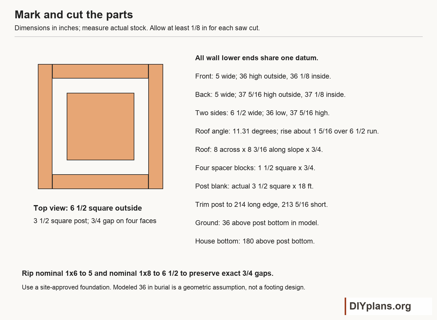
01 Cut and mark the shell
- Rip the 1x6 board to exactly 5 in and the 1x8 board to exactly 6 1/2 in. Actual thickness must be 3/4 in.
- Cut front,back and side blanks 37 1/2 in long. Mark the dimensions on the cut layout from one common lower-end datum; cut the roof slope 11.31 degrees.
- Cut four 1 1/2 in square spacers from 3/4 in offcuts. Cut the roof 8 in across and 8 3/16 in along the slope; bevel the short ends 11.31 degrees so they stand vertical.
Check: The dry-fitted shell is 6 1/2 in square outside and 5 in square inside.
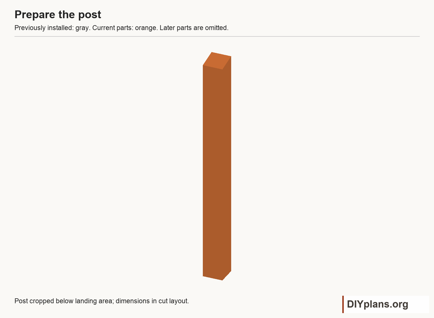
02 Prepare the untreated post
- Use one continuous 18 ft untreated naturally durable post, actual 3 1/2 in square. Obtain the site support design before buying or raising it.
- Trim its upper end to 214 in at the high edge and 213 5/16 in at the low edge, measured from its bottom. Keep the same 11.31 degree fall as the roof.
- Mark the future ground line 36 in above the bottom and the shell lower edge 180 in above the bottom. This puts the entrance 12 ft above the modeled ground.
- Roughen all post faces within the shell and the landing area below it. Roughen the inside walls and remove splinters. Leave these surfaces untreated and unpainted.
Check: Post top will sit 3 in below the matching underside of the roof over the post.
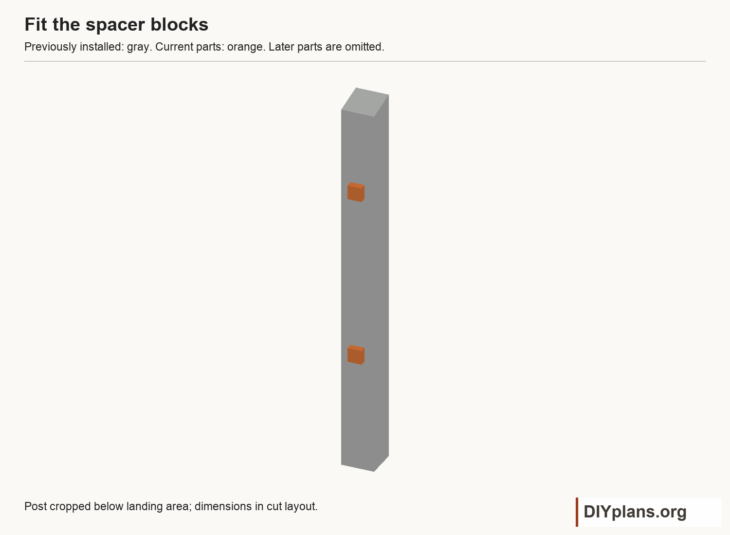
03 Locate the spacer blocks
- Work with the post supported horizontally. Mark its front face 6 and 24 in above the shell lower edge; mark its rear face 10 and 28 in above that edge.
- Set each spacer with its lower edge at the mark, centered across the 3 1/2 in post face. Hold blocks with clamps or a small spot of exterior wood glue while laying out the shell.
- Keep each block 1 1/2 in wide, leaving 1 in of clear post face on either side so bats can pass the blocks.
Check: Four blocks provide exact 3/4 in spacing; front and rear attachment heights are staggered.
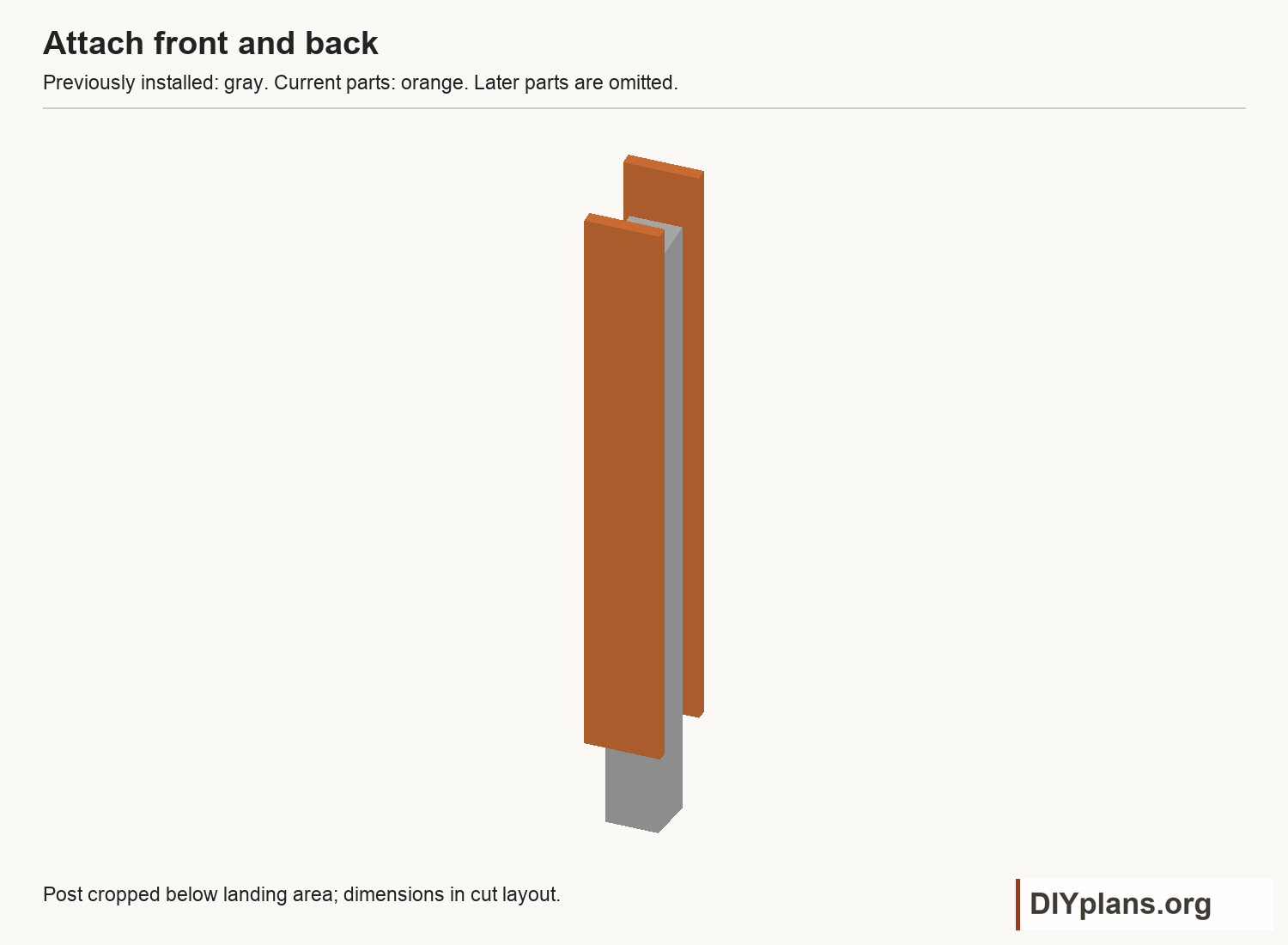
04 Fasten the front and back
- Set the front and back between the future side panels with their lower ends at the post mark. Match the low front and high back roof edges.
- At the center of each spacer, drill a clearance hole through the wall and spacer. Pilot the post to the lag manufacturer's specification.
- Install one 1/4 x3 in lag screw and washer through each block, four total. Tighten snugly without crushing the 3/4 in spacing.
Check: Walls stay parallel; each lag reaches 1 1/2 in into solid post and no tip enters a roost space.
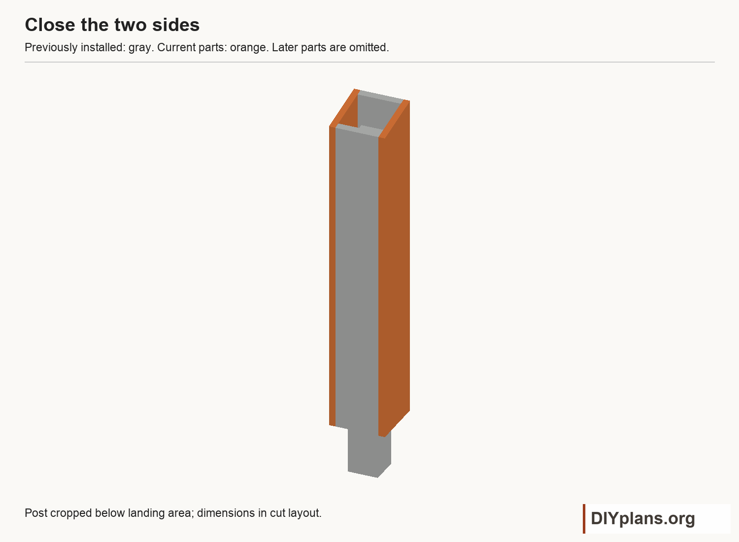
05 Attach the side walls
- Seal the long edges of the front and back. Fit the side panels outside those edges, aligning lower ends and roof slopes.
- Predrill through the side into the front/back edges. Fasten with 1 5/8 in screws every 6 in, starting 1 in from each end; keep centers 3/8 in from the side edges.
- Check the four open lower gaps with a 3/4 in gauge. Keep the bottom open and remove sealant squeeze-out.
Check: Each roost gap measures 3/4 in except where a spacer occupies it.
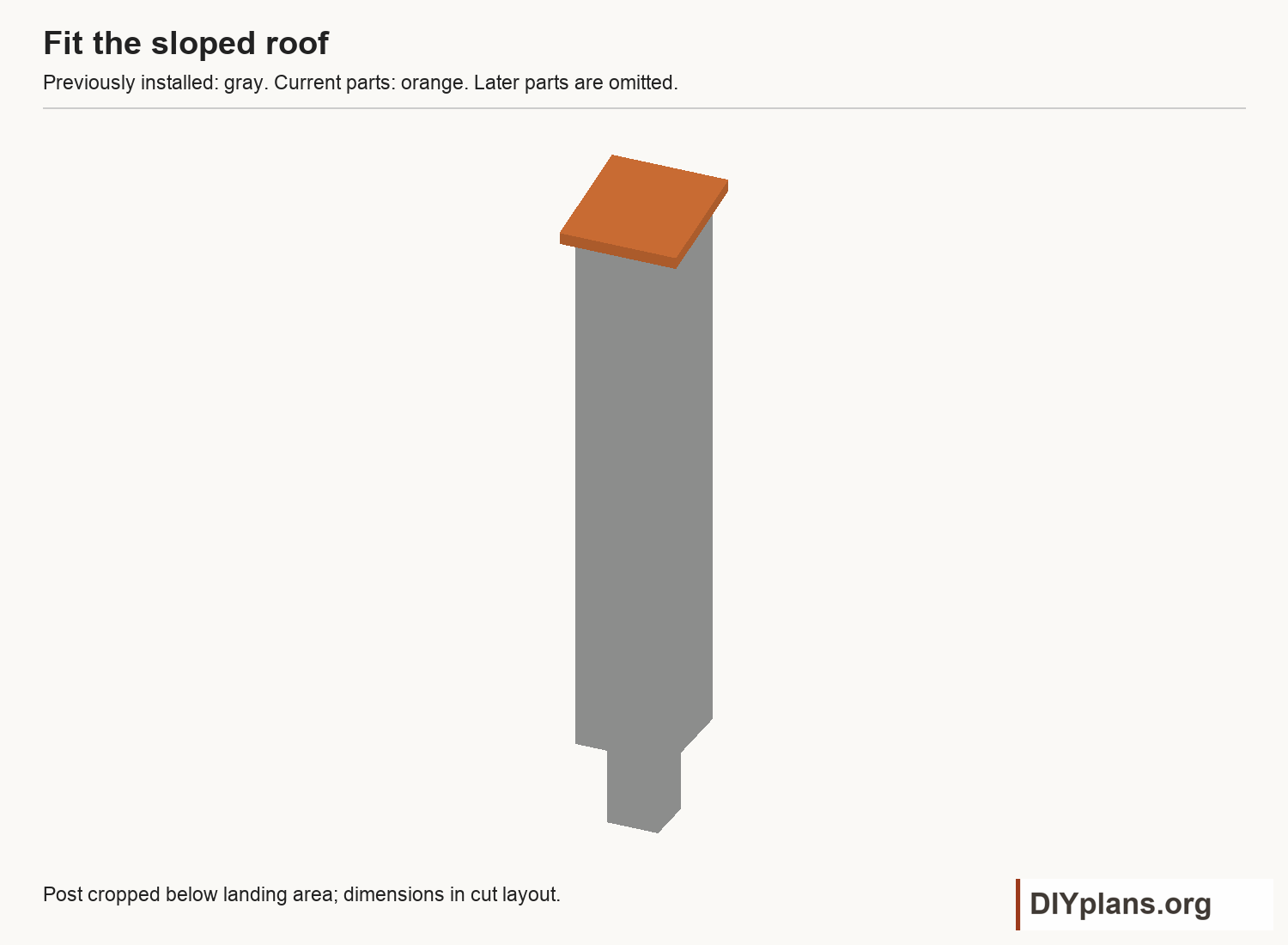
06 Fit the sloped roof
- Center the roof with 3/4 in horizontal overhang on all sides. Its underside follows the wall tops at 11.31 degrees.
- Seal the wall tops. Predrill and use four 1 3/4 in screws through the roof into wall edges, one over each wall.
- Cover the roof with formed flashing and drip edges. Seal its fasteners and the upper seams; keep the entrance and bypass spaces open.
- Prime and finish the exterior using water-based products and a shade appropriate to local summer temperatures. Allow the finish to cure; leave all roosting faces bare.
Check: Roof fits continuously along all four sloped tops and sheds water away from the openings.
07 Set the post and monitor the house
- Use a site-approved support and raising method for the 18 ft post, local wind, soil and frost conditions. The model shows 36 in burial only; it is not a footing design. Keep the complete post untreated rather than applying preservative near bat-accessible surfaces.
- Set the house with at least 12 ft of unobstructed air below the entrance and no nearby branches or predator access. Recheck clearance if the support design changes ground level or embedment.
- Confirm the post is plumb and secure before removing temporary support. Inspect groundline condition and anchors periodically; replace deteriorated components only when the roost is unoccupied.
Check: Mounting support has been checked for this site, and every entrance and roost passage remains clear.
Sources
Functional dimensions informed by the cited Washington Department of Fish and Wildlife woodworking sheet. CAD, instructions, schedules and illustrations authored for DIY Plans.