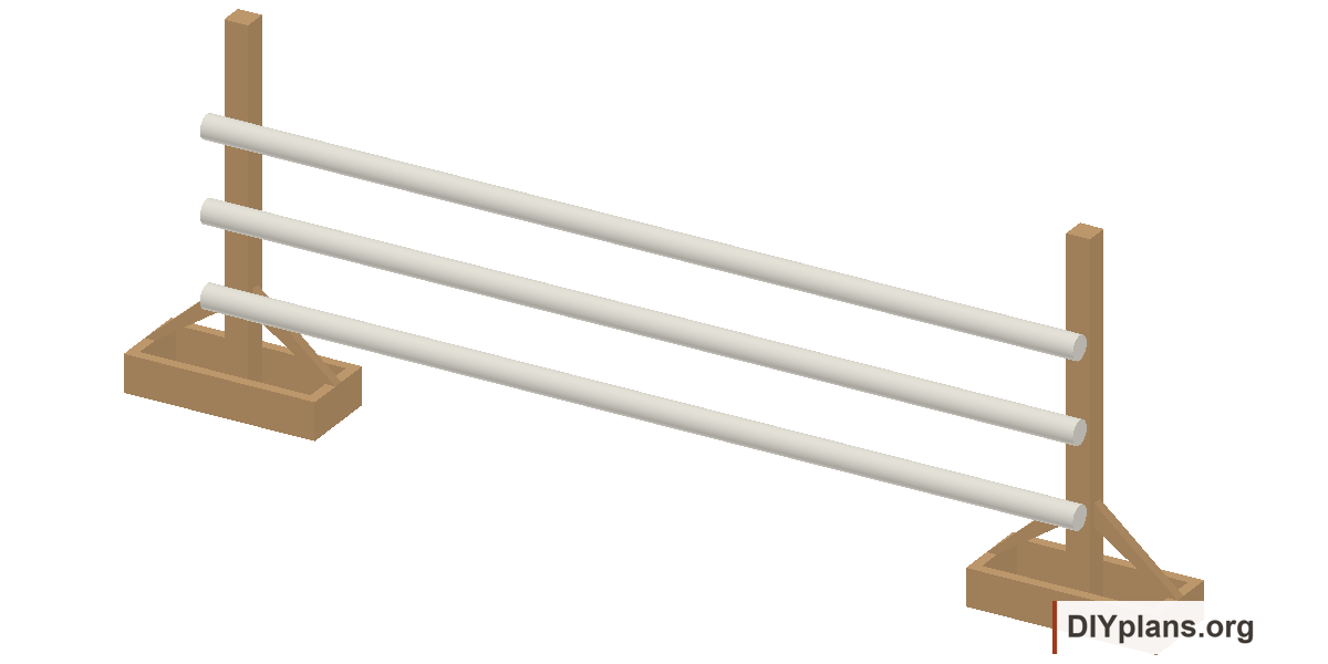
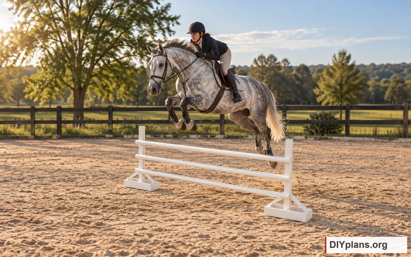
Before you start
- Design inspiration: dimensioned visual reference and editable concept geometry, not a construction plan.
- Use the files to study proportions and possible variations. A physical adaptation needs its own connection, release and installation details.
- Rail supports, track mounting and base/brace fastening are not specified. No release performance, stability or safe riding height is established.
- The 3 1/2 in round rails are modeled envelopes. Actual pole material, diameter, mass and end clearance must suit the selected support system.
- Changing to inward-facing cups requires coordinated changes to pole length, post spacing and actual rail-top heights.
Dimensions and opening sizes
- Clear opening between postsIllustrated concept geometry; no use or load rating.
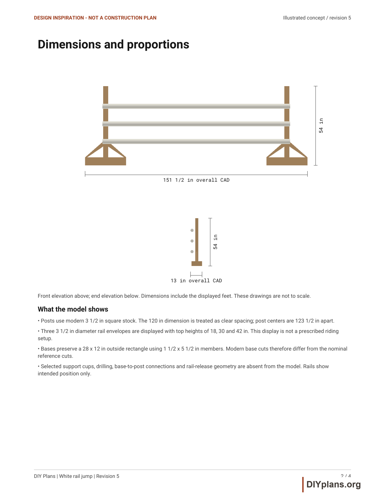
- 120 in
- Post lengthIllustrated concept geometry; no use or load rating.
- 54 in
- Rail lengthIllustrated concept geometry; no use or load rating.
- 128 in
- Base depthIllustrated concept geometry; no use or load rating.
- 12 in
- Base widthIllustrated concept geometry; no use or load rating.
- 28 in
Shopping list
| Buy | Material | Stock size |
|---|---|---|
| 1 board | 4 x 4 lumber | 10 ft |
| 3 board | Straight rail-quality 4 x 4 lumber | 12 ft |
| 2 board | 2 x 6 lumber | 10 ft |
| 1 board | 2 x 4 lumber | 8 ft |
Quantity notes
Indicative full-stock allocation for comparing the illustrated timber concept. This is not a complete purchase order. Hardware, structural connections, coatings, ground anchorage and installation materials are outside this timber takeoff.
- 4 x 4 lumber, 10 ft: Two 54 in posts with kerf allowance.
- Straight rail-quality 4 x 4 lumber, 12 ft: One 128 in rail blank from each; inspect before machining.
- 2 x 6 lumber, 10 ft: Each board yields 28 + 28 + 9 + 9 in with kerfs.
- 2 x 4 lumber, 8 ft: Four 18 in brace blanks with kerfs.
Tools & equipment
- FreeCAD for editing the native solid model
- STEP-compatible CAD software for exchange geometry
BEFORE YOU BUILD
Use this work at your own risk
No person or organization makes any guarantee or warranty, express or implied, regarding this design, its documentation, digital files, or website views. They are not professional services and do not create an architect-client or other professional-client relationship. No promise is made about accuracy, completeness, reliability, code compliance, or fitness for your project.
Buildings and building projects are complex, and many things can go wrong. You are responsible for checking dimensions and site conditions, choosing suitable materials and methods, obtaining permits, following codes and manufacturer instructions, and getting qualified professional help when needed. To the fullest extent permitted by law, DIYPlans.org disclaims liability for damages resulting from use of this work. Read the FAQ about your responsibilities.
CC CC BY-NC-SA 4.0 InternationalShare and adapt this free design for noncommercial purposes with appropriate credit. Link to the license, indicate changes, and license adaptations under the same terms.
Instructions
01 Read the two standards
- The illustrated posts are 54 in tall and have 120 in between their inside faces. Each base is 28 x 12 in, with two braces. The full model is wider than the opening because the bases project beyond the posts.
Check: Distinguish the clear opening from the full footprint.
02 Look at the rail arrangement
- Three 128 in rail envelopes are shown forward of the posts. Their tops are displayed at 18, 30 and 42 in; these heights illustrate the composition rather than prescribe a riding exercise.
Check: Locate the three rails and their offset from the posts.
03 Treat support hardware as a separate design
- Cups, tracks, attachment holes and release behavior are deliberately absent. A 128 in rail cannot simply move between inward-facing cups in a 120 in clear opening; pole length, spacing and support geometry must be coordinated.
Check: Recognize that the model does not provide a ready-to-fit cup layout.
04 Explore the appearance
- Use a copy of the CAD to compare rail colors and standard shapes. Keep this concept separate from any manufacturer-specific support design or site arrangement.
Check: Save the visual study separately from the supplied reference model.