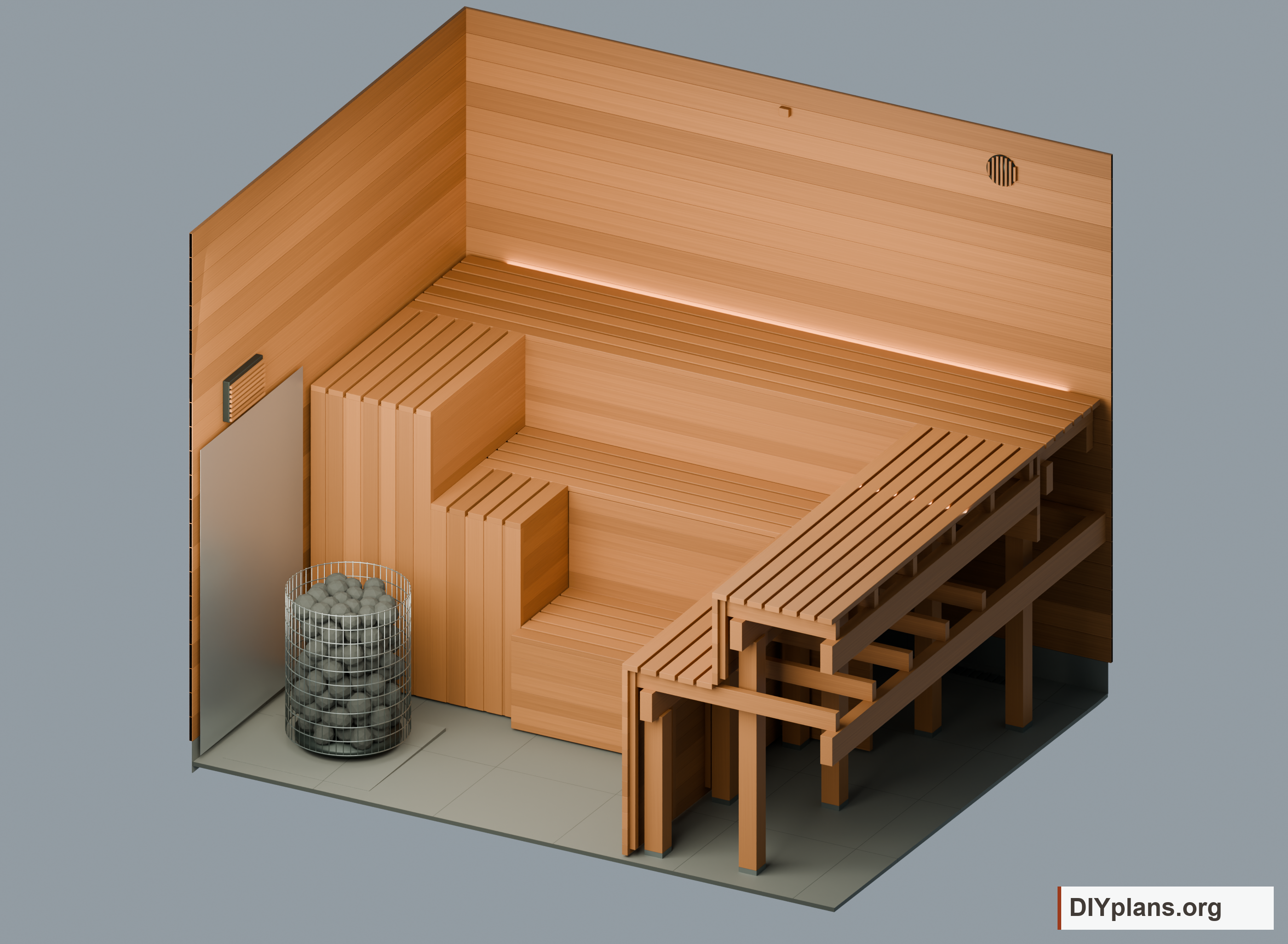
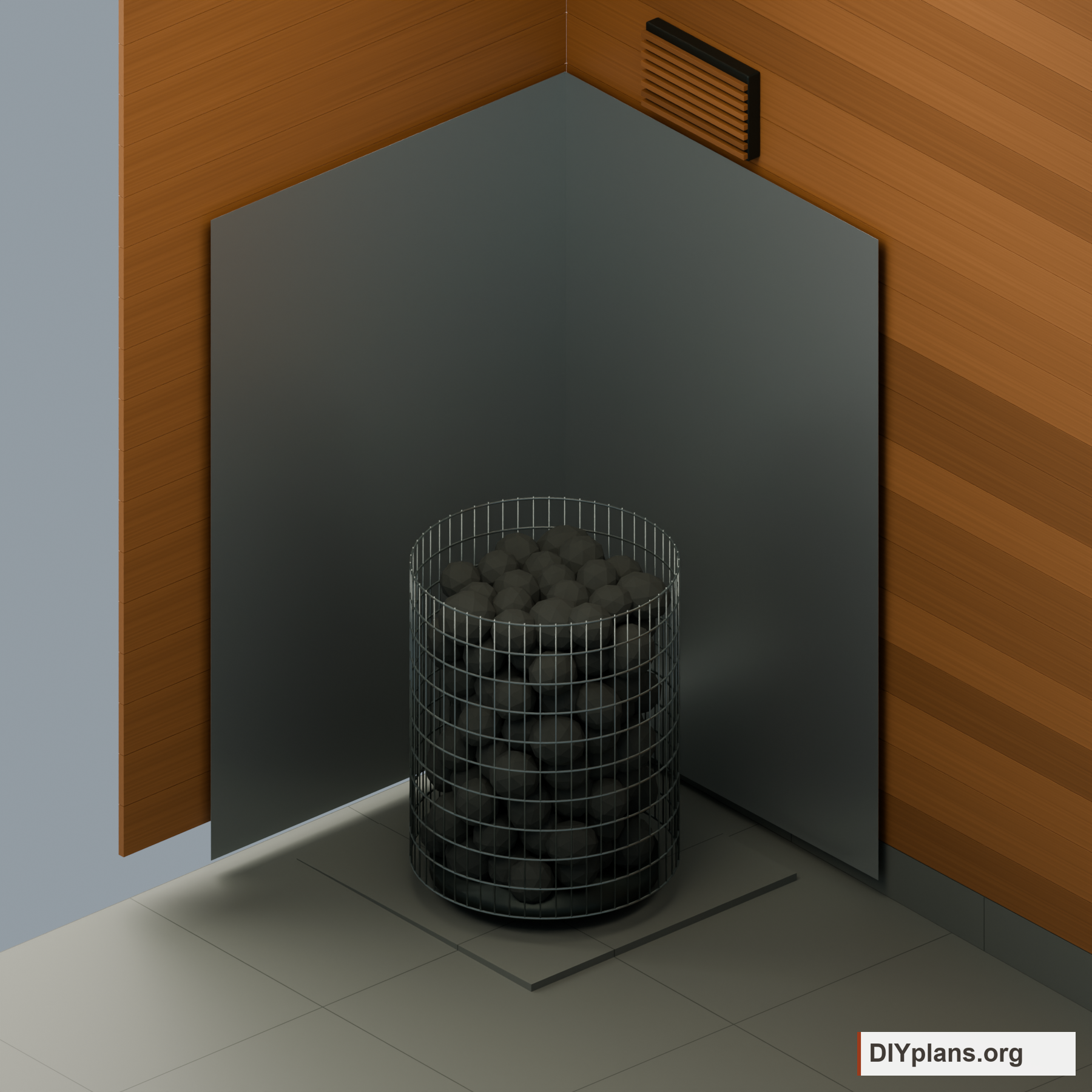
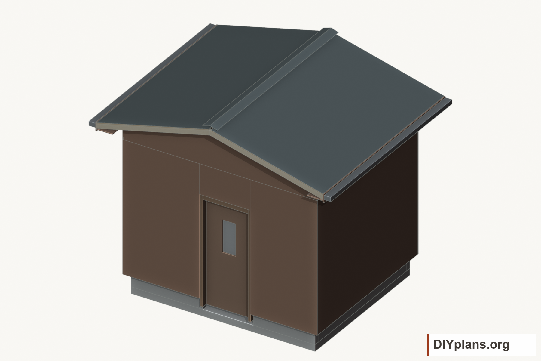
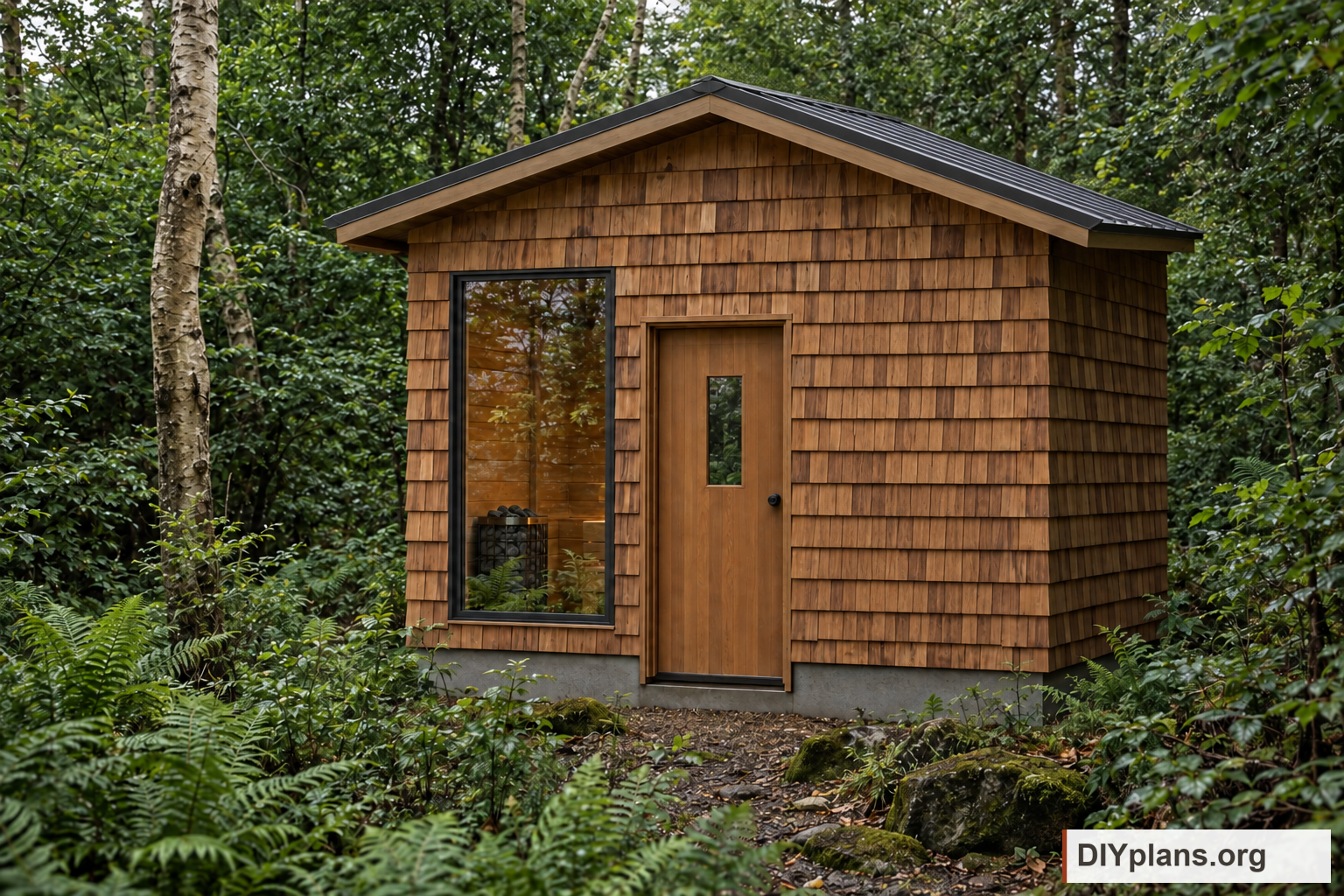
Dimensions and opening sizes
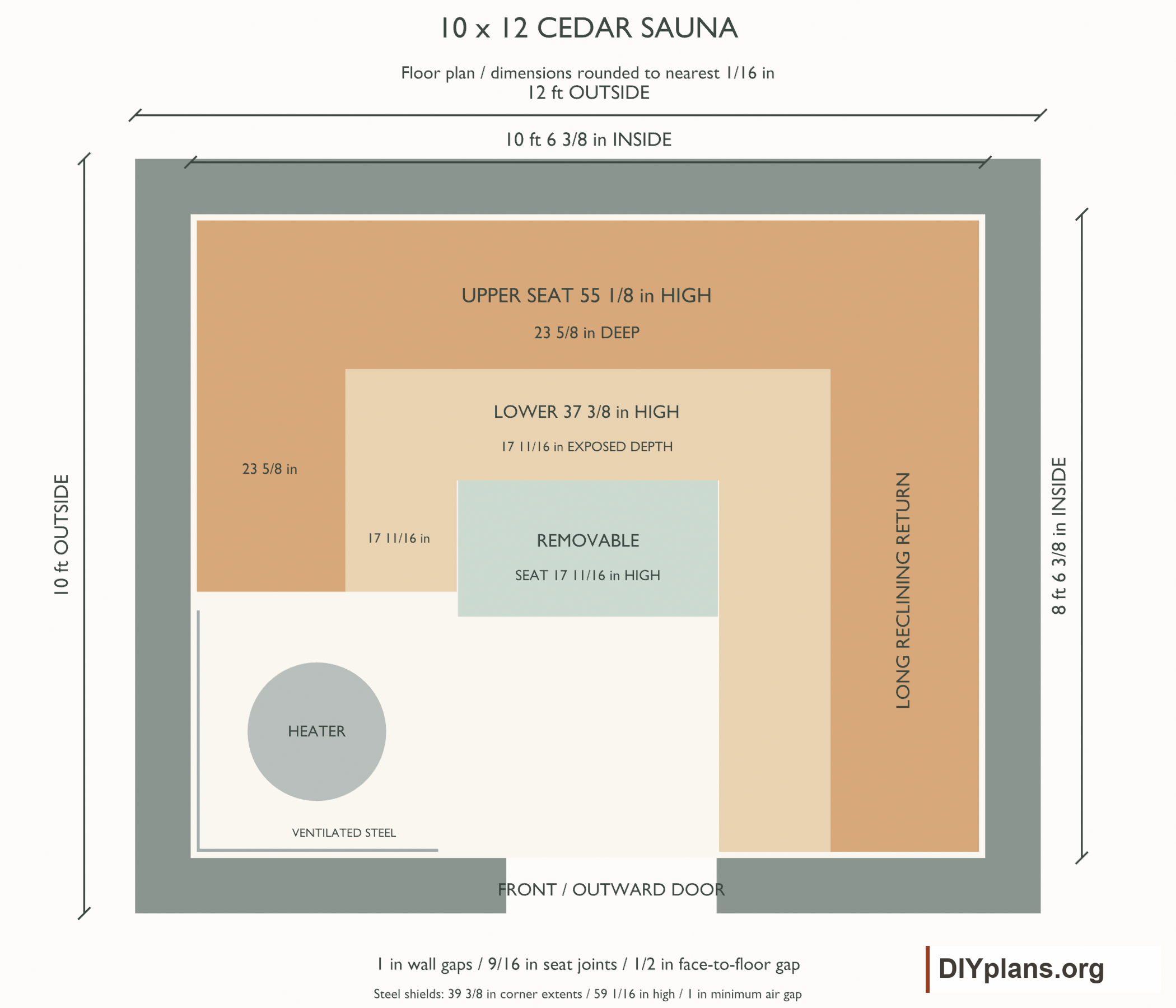
- Finished exterior widthAcross the front.
- 12 ft
- Finished exterior depthFront to rear.
- 10 ft
- Inside widthBetween finished wall faces.
- 126 3/8 in
- Inside depthFront to rear.
- 102 3/8 in
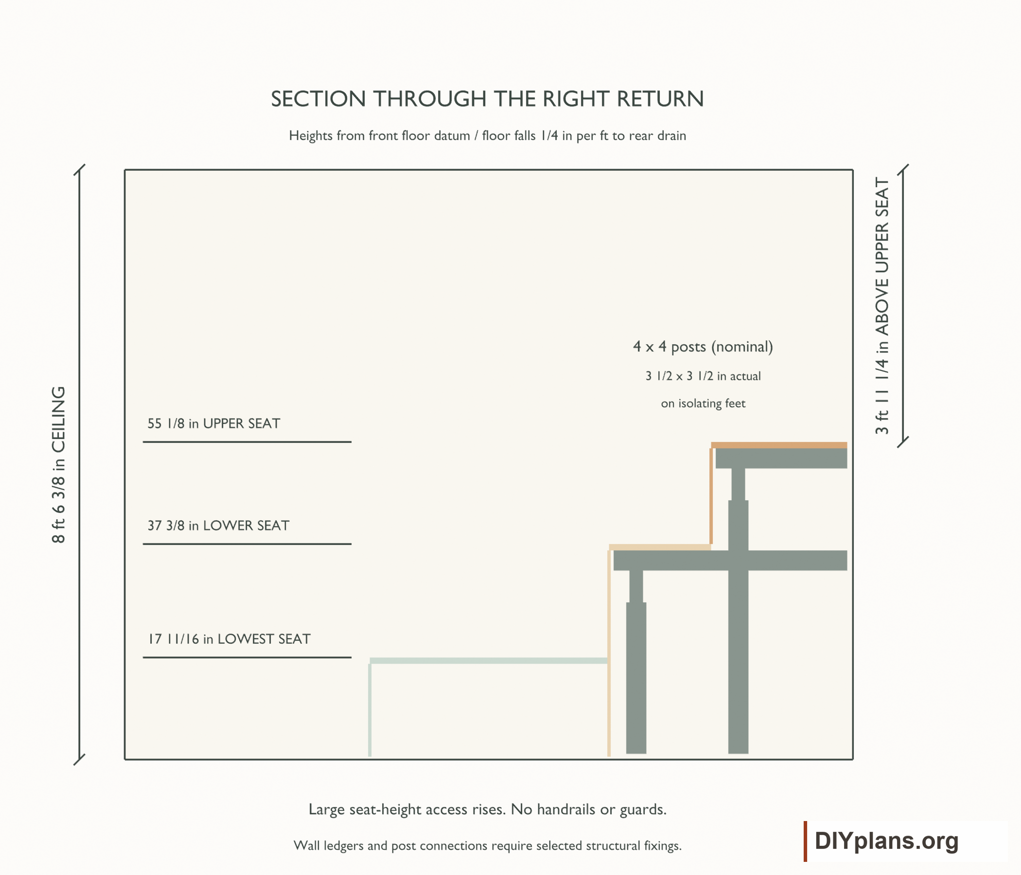
- Ceiling heightAbove the front floor datum.
- 102 3/8 in
- Upper seating heightAbove the front floor datum.
- 55 1/8 in
- Lower seating heightAbove the front floor datum.
- 37 3/8 in
- Lowest seating heightAbove the front floor datum.
- 17 11/16 in
- Upper bench depthRear and return seating.
- 23 5/8 in
- Exposed lower bench depthIn front of the upper benches.
- 17 11/16 in
- Facing clearance above floorScribed to the sloped floor.
- 1/2 in
- Roof overhangBeyond the finished exterior walls.
- 11 13/16 in
Shopping & cut lists
Get the shopping and cut lists
Includes all available CAD files, shopping lists and cut lists for every configuration of this plan. One payment, $19 USD.
Get the plan package · $19Secure checkout with Stripe. Your account is created after payment.
Already purchased? Sign in to access your plans.
Tools & equipment
- Tape measure, framing square, chalk line and laser level
- Circular saw or track saw, miter saw and suitable blade
- Router or shaper for cedar profiles, plus sanders and edge-rounding tools
- Drill/driver, pilot bits, countersink and clamps
- Tools for the selected structural fasteners and connectors
- Temporary wall and roof bracing, safe access equipment and helpers
- Tools for the selected waterproofing, tile and drain systems
- Airflow meter, temperature probes and a CO2 meter for commissioning
- Eye, hearing and dust protection appropriate to the work
BEFORE YOU BUILD
Use this work at your own risk
No person or organization makes any guarantee or warranty, express or implied, regarding this design, its documentation, digital files, or website views. They are not professional services and do not create an architect-client or other professional-client relationship. No promise is made about accuracy, completeness, reliability, code compliance, or fitness for your project.
Buildings and building projects are complex, and many things can go wrong. You are responsible for checking dimensions and site conditions, choosing suitable materials and methods, obtaining permits, following codes and manufacturer instructions, and getting qualified professional help when needed. To the fullest extent permitted by law, DIYPlans.org disclaims liability for damages resulting from use of this work. Read the FAQ about your responsibilities.
Instructions
01 Set out the base
- Complete the site-specific foundation, wall bracing, header, roof-truss and exterior-landing selections before starting construction. This is an unbuilt design concept with checked geometry; the foundation and trusses shown reserve space and are not fabrication designs.
- Use feet and fractional inches for layout. Dimensions are rounded to the nearest 1/16 in unless a minimum, maximum or product thickness is specified. Set the datum at the finished interior front-left corner, at the front floor height; measure x to the right, y toward the rear and z upward.
- Mark the finished exterior wall rectangle at 12 ft x 10 ft. Put the entrance on the 12 ft side.
- Allow 11 13/16 in roof overhang beyond every finished wall. Reserve a level exterior landing and drainage around the building.
- Have the local foundation design establish bearing, frost protection, reinforcement, anchorage and finished floor height. Place the specified compacted capillary break and bearing-rated insulation.
- Include approximately 605 lb for the HIVE 18 with its 552 lb stone allowance, plus the plinth, in the foundation and floor design.
Check: The exterior wall rectangle is 12 ft x 10 ft and its diagonals agree.
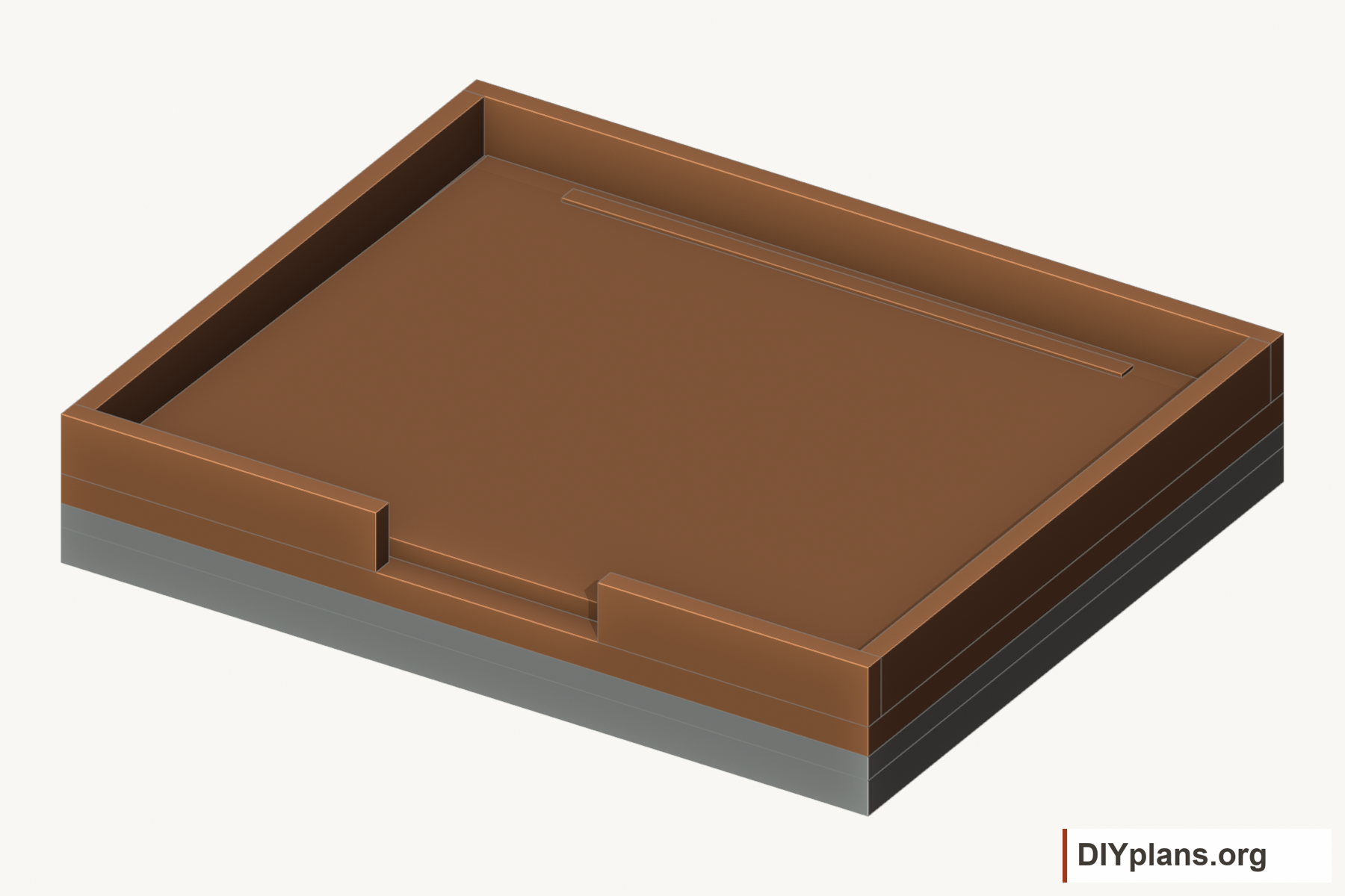
02 Build the slab and drain base
- Reserve the electrical supply and controller arrangement for the 18 kW, 240 V heater with the electrician before placing the slab and service rough-ins.
- Select a compatible floor membrane, bonded drain, tile and sauna-foil transition before setting the drain rough-in and floor heights.
- Install the drain rough-in and services before pouring. Center the 94 1/2 in rear channel at x=63 3/16 in, y=98 7/16 in.
- Build the selected slab and raised perimeter curb. Keep the front curb interrupted between x=48 1/4 in and x=85 5/8 in for the door opening.
- Form the cementitious floor base for a 1/4 in fall per foot to the rear drain, with a short reverse fall behind it. The 4 15/16 in slab shown is a coordination allowance, not a site footing specification.
Check: The drain, sill opening and floor fall match the plan and chosen waterproofing system.
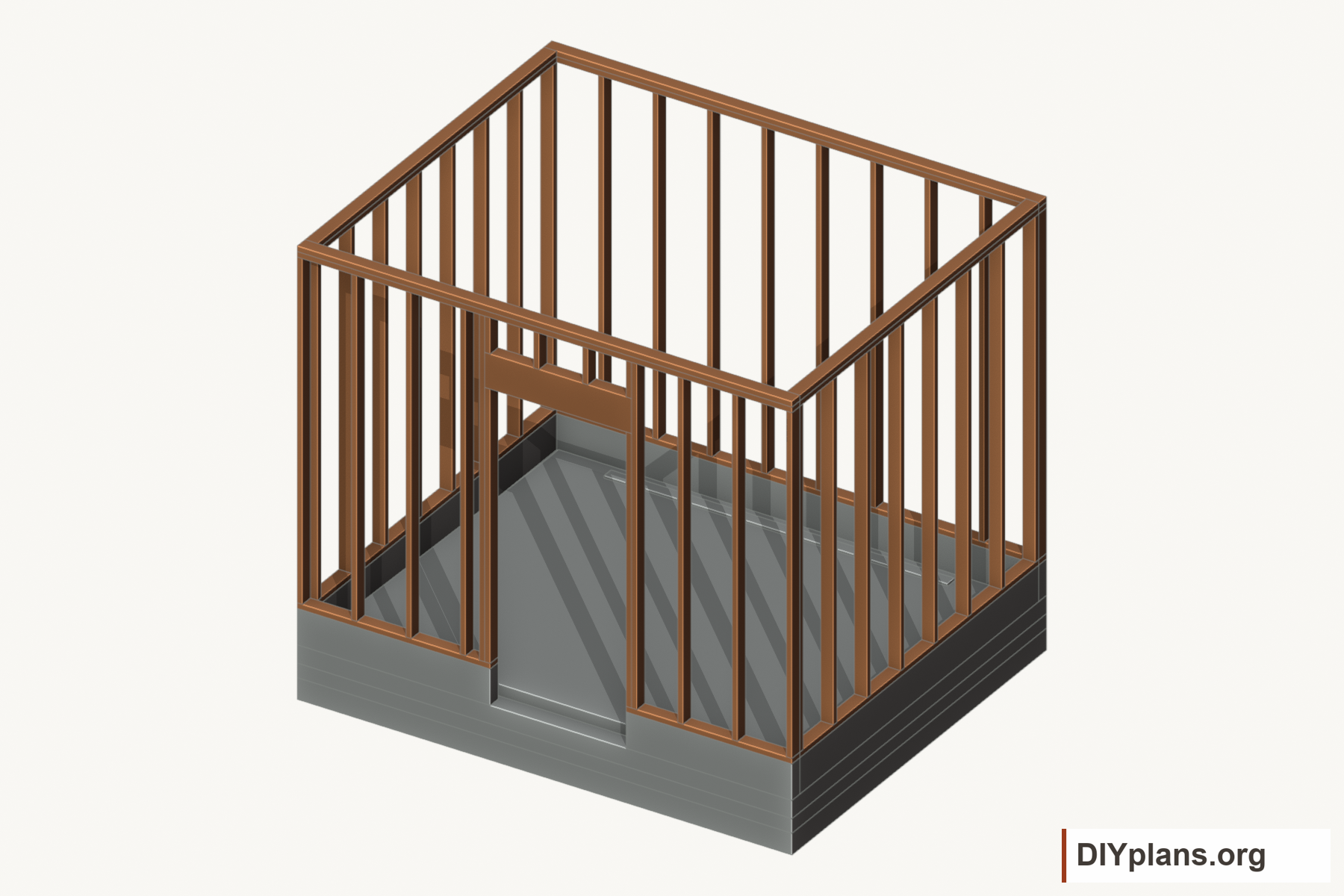
03 Frame the walls and door
- Fit sill isolation and anchor the plates to the selected foundation detail. Use nominal 2x4 framing, actual 1 1/2 x 3 1/2 in, at the stations in the wall schedule, no more than 15 15/16 in apart.
- Frame the provisional 37 3/8 x 81 1/2 in door rough opening between x=48 1/4 in and x=85 5/8 in. Confirm it with the selected factory door before cutting.
- Install the selected header on jack studs, the king studs and 9 13/16 in coordination-length cripples. Lap top plates and add corner and sheathing-edge backing to the local bracing design.
Check: The door rough opening and wall heights match the selected components.
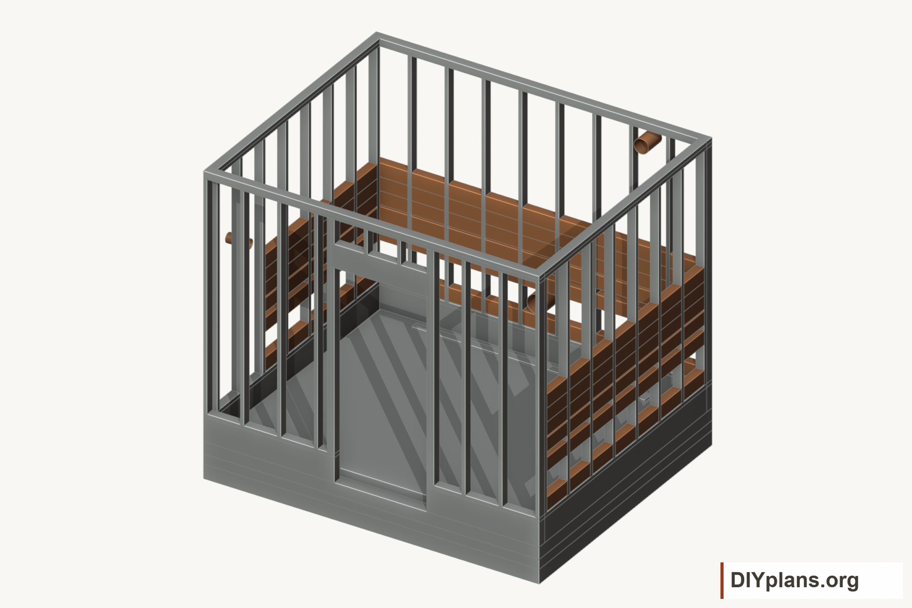
04 Fit blocking and service sleeves
- Select the bench timber grades, ledger fixings, post-to-beam ties, moisture-isolating feet and joist fixings. Size the wall blocking and compression spacers for those connections before installing them.
- Fit the wall blocking shown in the component schedule. Connect its ends to the studs for the selected wall-ledger fixings.
- Place the supply sleeve, about 3 15/16 in in diameter, in the left wall at x=0 in, y=17 1/2 in, z=64 15/16 in. Place the low exhaust sleeve, about 7 7/8 in in diameter, in the rear wall at x=63 3/16 in, y=102 3/8 in, z=18 1/2 in. Match sleeves and duct fittings to the selected equipment before framing the openings.
- Place the drying sleeve, about 5 7/8 in in diameter, in the rear wall at x=105 1/2 in, y=102 3/8 in, z=94 1/2 in. Keep sleeves clear of studs and blocking.
- Reserve the common space below the benches. Keep the central cleaning opening and rear drain clear of supports and pipework.
Check: Ledger backing and service sleeves are in place without cutting through studs.
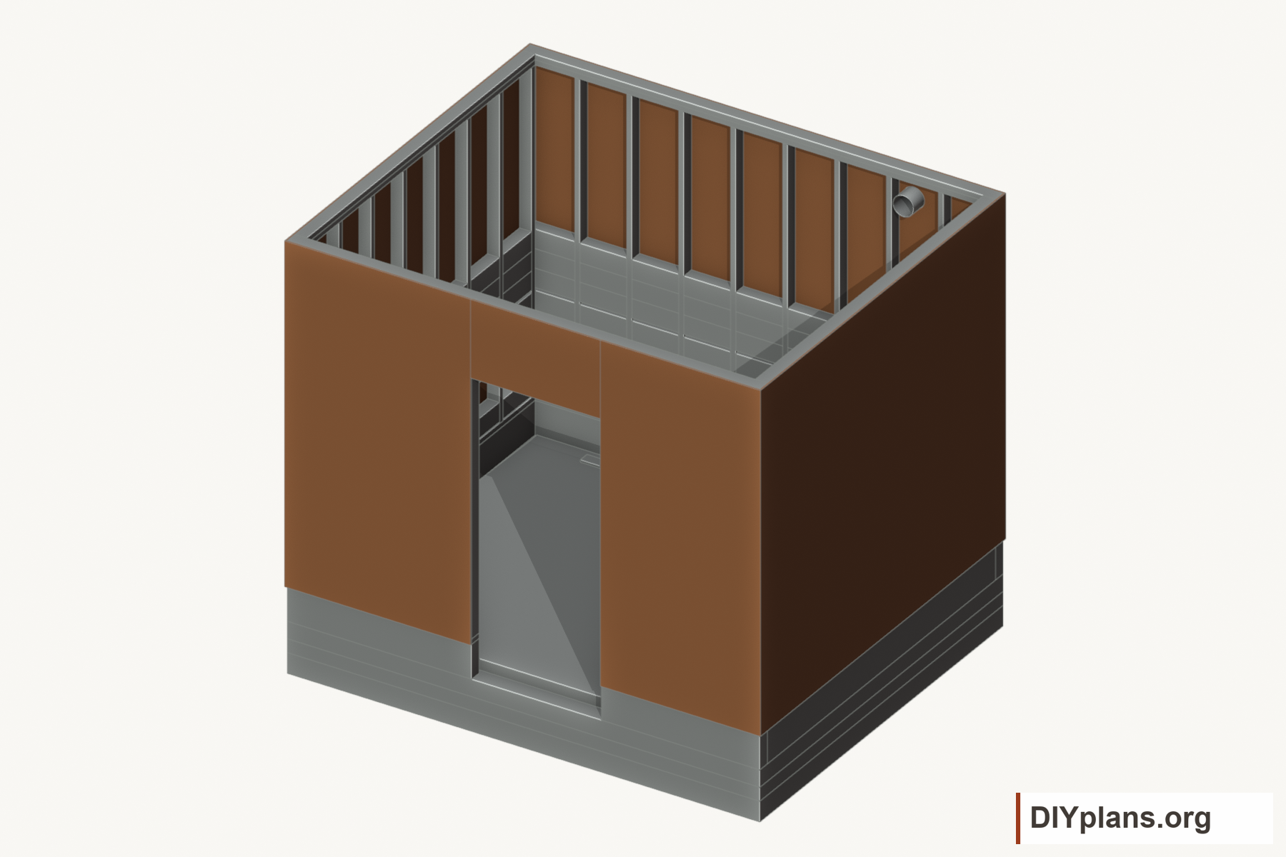
05 Sheathe and weatherproof the walls
- Fasten structural plywood using the local shear/bracing and edge-support schedule. Flash the base and the door sill pan with end dams.
- Apply a vapor-open water-resistive barrier. Lap it over head flashings, seal duct penetrations and connect it to the sill pan.
- Keep the drainage path outside the structural sheathing continuous. The interior sauna foil belongs on the hot side of the insulation.
Check: Wall drainage and sill flashing have a continuous path to the exterior.
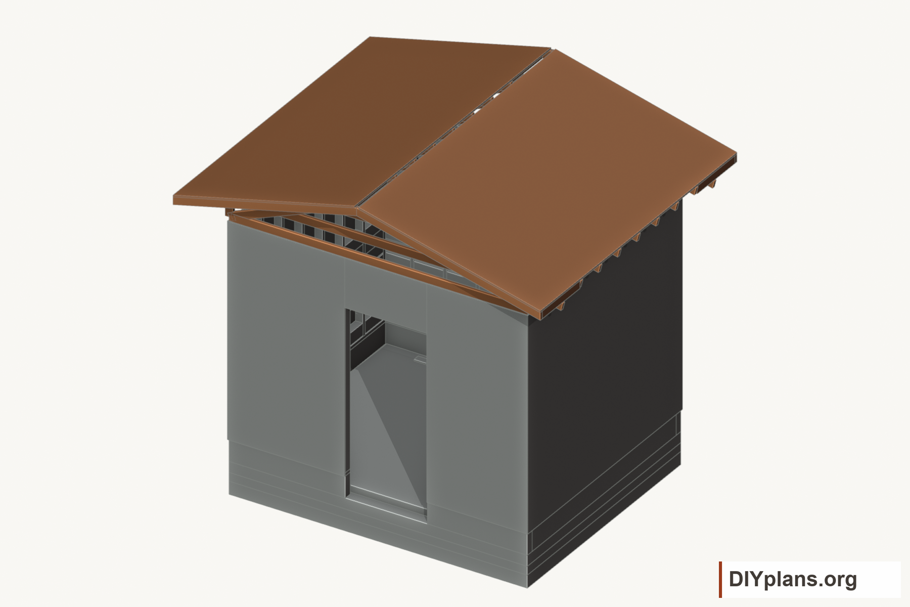
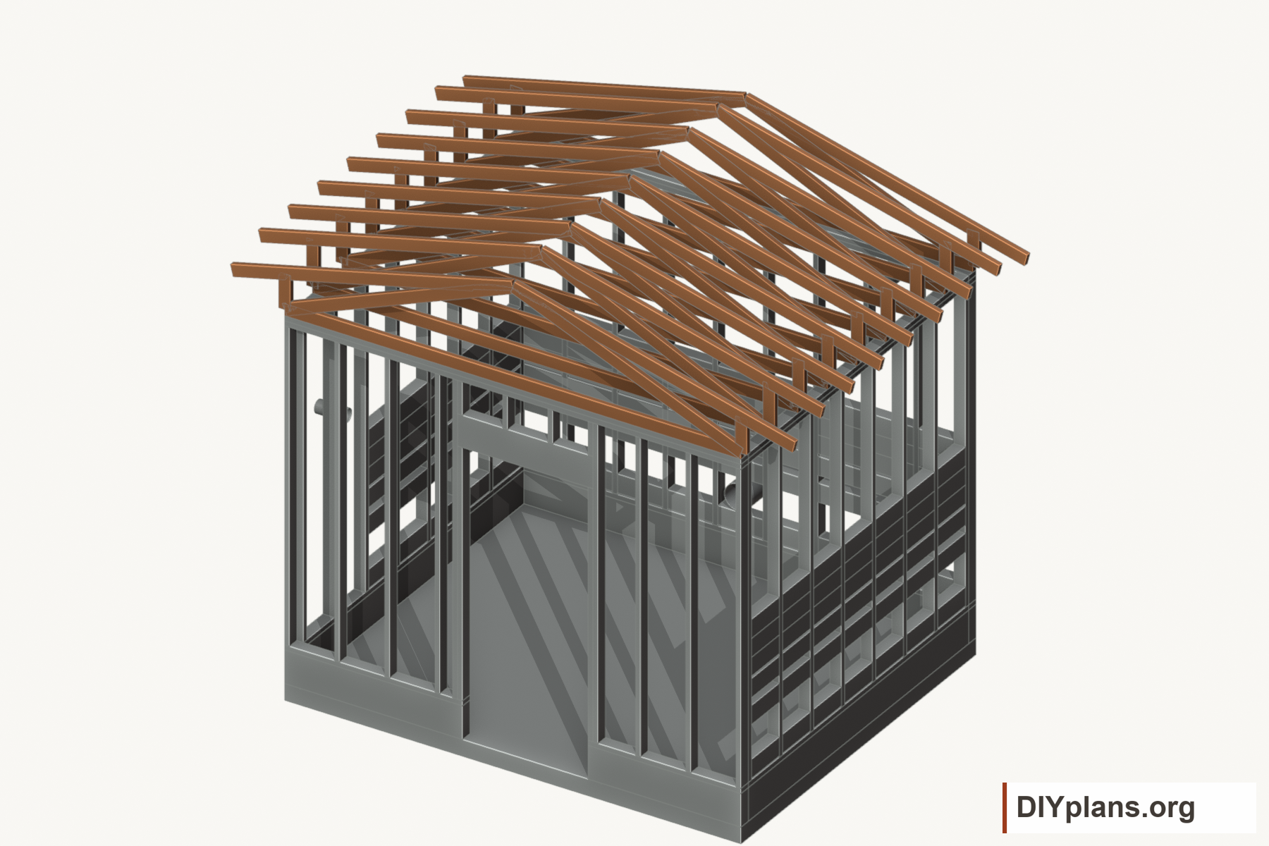
06 Install the roof structure and deck
- Select a complete metal-roof system with compatible underlayment and flashings, approved for 3:12 pitch and the actual local exposure.
- Order nine raised-heel truss positions for the 3:12 roof; the supplier must finalize member sections, webs, plates, bearings, bracing and connections.
- Have the supplier support the 15 3/4 in projection beyond the structural wall face, equivalent to 11 13/16 in beyond finished cladding, including gable lookouts.
- Install the roof deck on the chord top faces and apply the selected underlayment. Maintain the specified vented eave-to-ridge route. The model is not a truss fabrication drawing.
Check: The ordered truss package, bracing and roof deck match the local roof design.
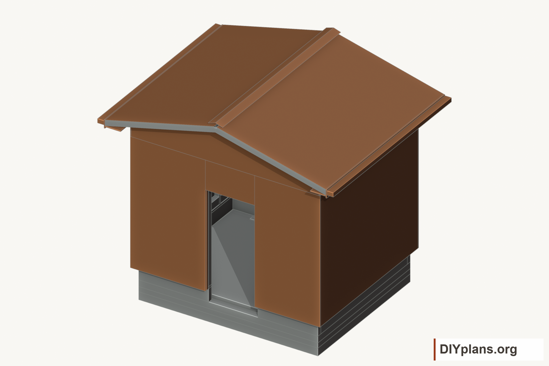
07 Finish the exterior envelope
- Close the gables and raised heels, continuing the WRB and drained cladding support. Keep roof vent inlets open with insect screening.
- Fit 1 15/16 in continuous exterior mineral wool, 3/4 in rainscreen battens and 3/4 in cladding. Size batten fasteners for the exterior insulation thickness and wind loads.
- Install the selected metal roof, ridge, barge and eave flashings, gutters and drainage over the underlayment.
Check: Cladding drainage and eave-to-ridge ventilation remain open.
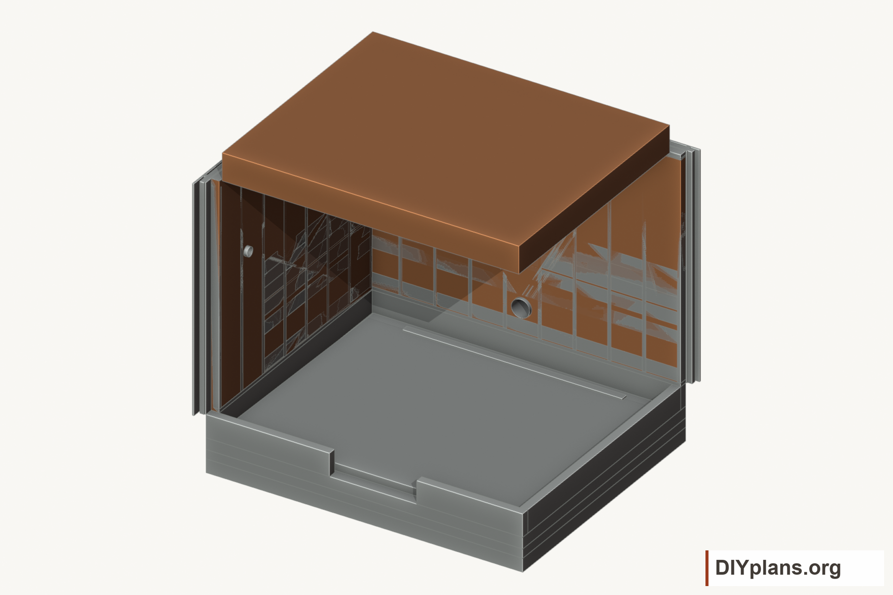
08 Insulate the room
- Fit mineral wool in the wall cavities without voids. Trim it around framing, backing and ducts without compressing it.
- Place 11 13/16 in attic insulation above the flat ceiling. Fit wind-wash dams and baffles to maintain at least 2 in of clear ventilation space at the heels.
- Keep the building roof ventilation separate from the sauna room ventilation.
Check: Insulation is continuous and the roof ventilation path is clear.
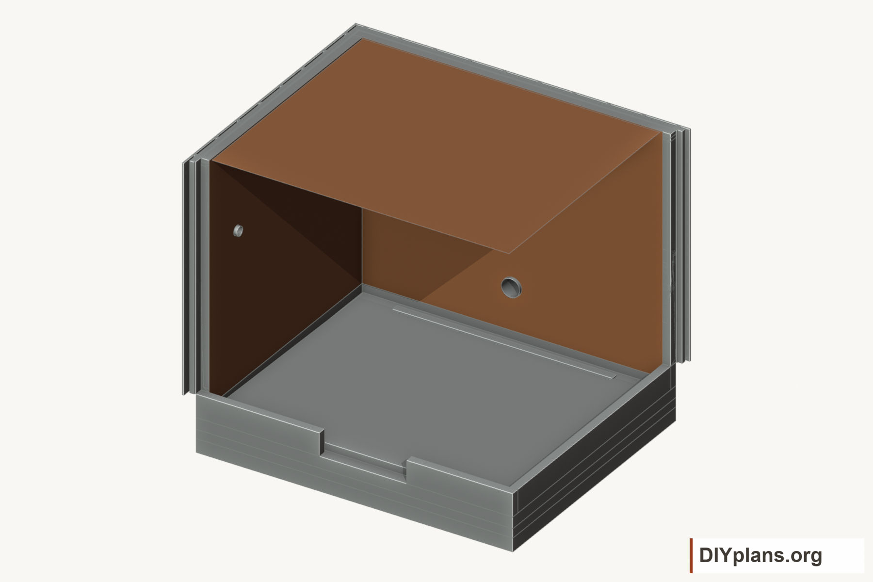
09 Seal the sauna foil
- Run the sauna-rated aluminum vapor layer continuously across the walls and ceiling. Tape seams with compatible high-temperature foil tape.
- Seal around each duct sleeve, cable passage and structural spacer. Keep the wall-to-ceiling foil joint sealed behind the lining gap.
- Connect the foil to the selected floor waterproofing upstand using that system's approved transition detail.
Check: Foil seams and service penetrations are sealed.
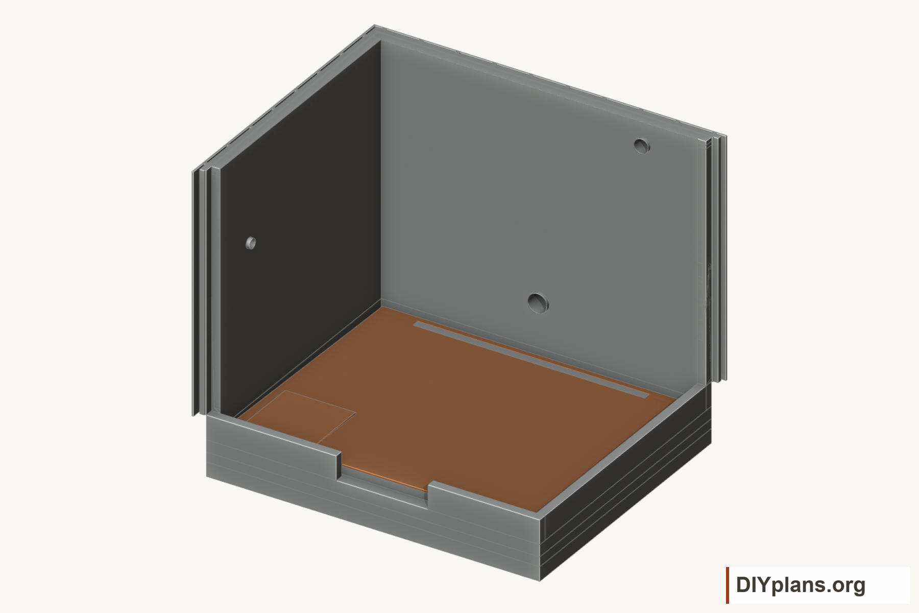
10 Waterproof and tile the floor
- Apply the selected sauna/wet-room waterproofing system, including a bonded drain flange and wall upstands. Test it before covering.
- Tile the floor with a 1/4 in fall per foot and the short rear reverse fall. Finish the channel grate flush and retain a cleaning route to its removable parts.
- Build the noncombustible level heater plinth between x=3 15/16 in and x=32 11/16 in, and between y=3 15/16 in and y=32 11/16 in. Support approximately 605 lb for the heater and its 552 lb stone allowance, plus the plinth, on the selected floor structure.
Check: The membrane test passes and water drains without pooling.
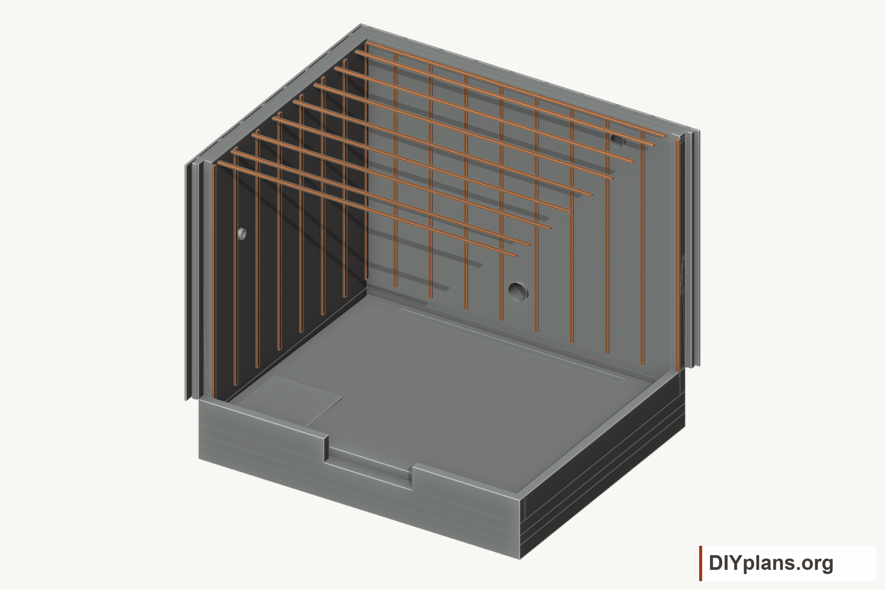
11 Install the lining battens
- Fix 3/4 in interior battens at the wall stud stations and ceiling supports. Add backing at panel ends and ceiling perimeters.
- Keep the interior air space continuous. Place solid compression spacers at structural bench anchors so their loads do not crush the lining or the gap.
- Seal each spacer and fixing through the foil before the benches hide it.
Check: Lining battens and bench-anchor spacers are fixed over the sealed foil.
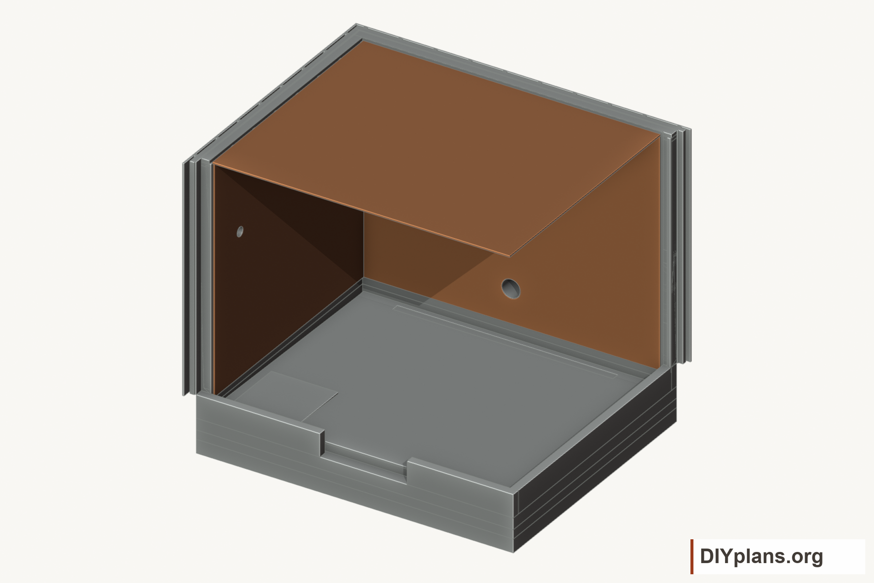
12 Line the walls and ceiling
- Install clear cedar lining on the wall and ceiling battens. Run the wall boards horizontally and the ceiling boards front-to-back.
- Keep wall lining at least 4 in above the local floor and leave at least 1/4 in below the ceiling for the trim joint. Keep the sauna foil sealed behind these drying gaps.
- Keep the finished ceiling at 102 3/8 in above the front floor datum. Conceal fixings and soften exposed edges.
- Choose a sauna-suitable 5/8 in finished lining profile. Check its net coverage and movement allowance before ordering or cutting.
Check: Clear cedar lining is complete with the specified drying and trim gaps.
13 Support the benches on posts
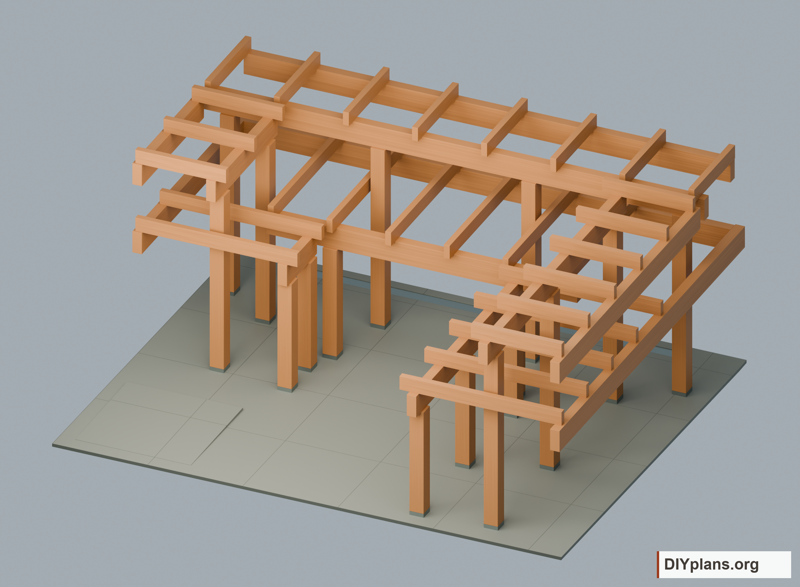
- Check that the intended users can climb the broad access seats. The successive rises are approximately 18 1/2, 19 11/16 and 17 11/16 in with no handrails; these seats are not conventional stairs.
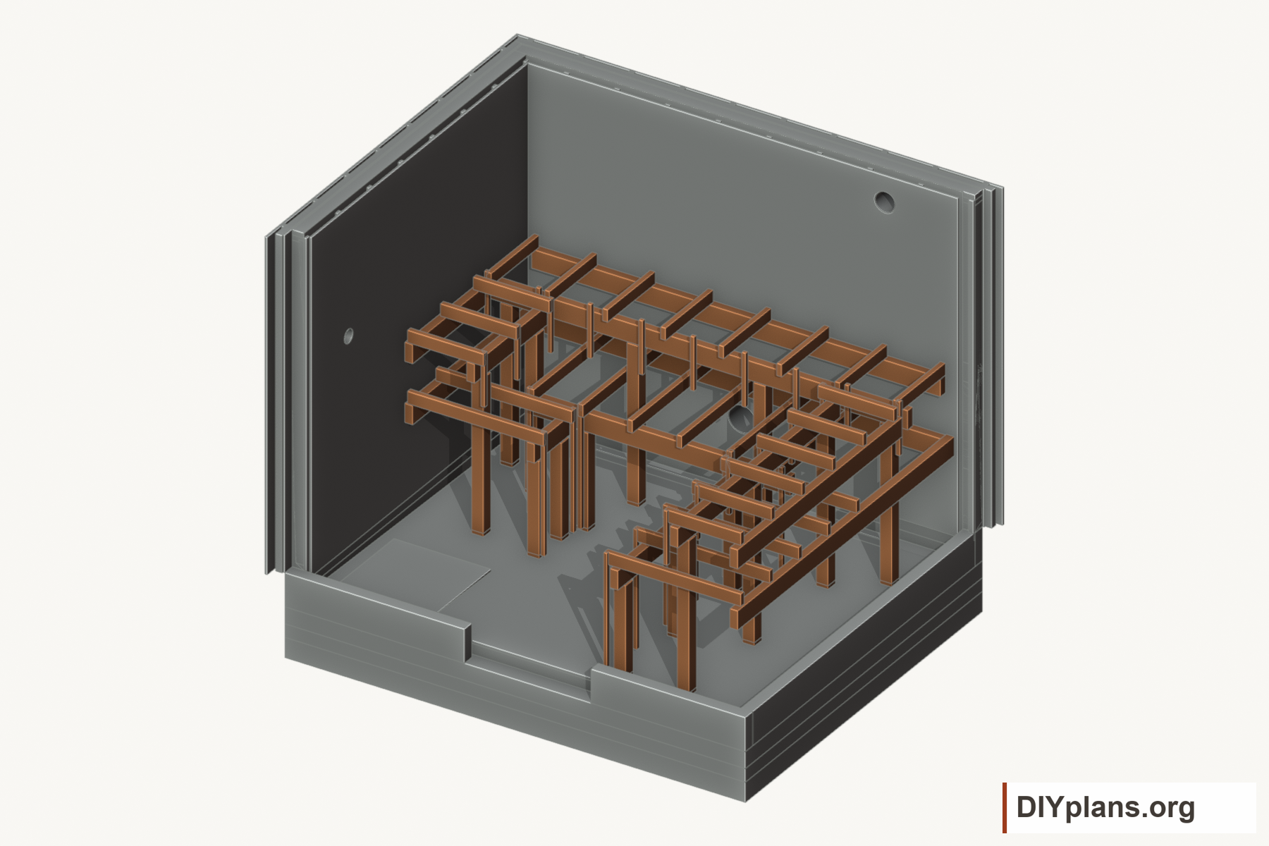
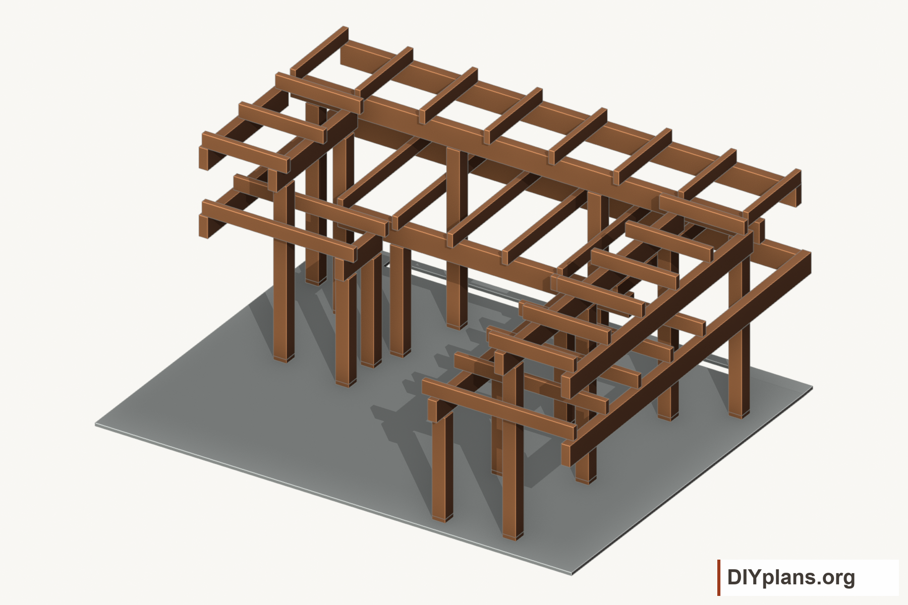
- Fix the 2 3/8 x 5 1/2 in rear wall ledgers through solid spacers into the blocked wall framing. These are finished section sizes; select suitable stock and connections before milling. Use the selected structural fixings and seal the foil penetrations.
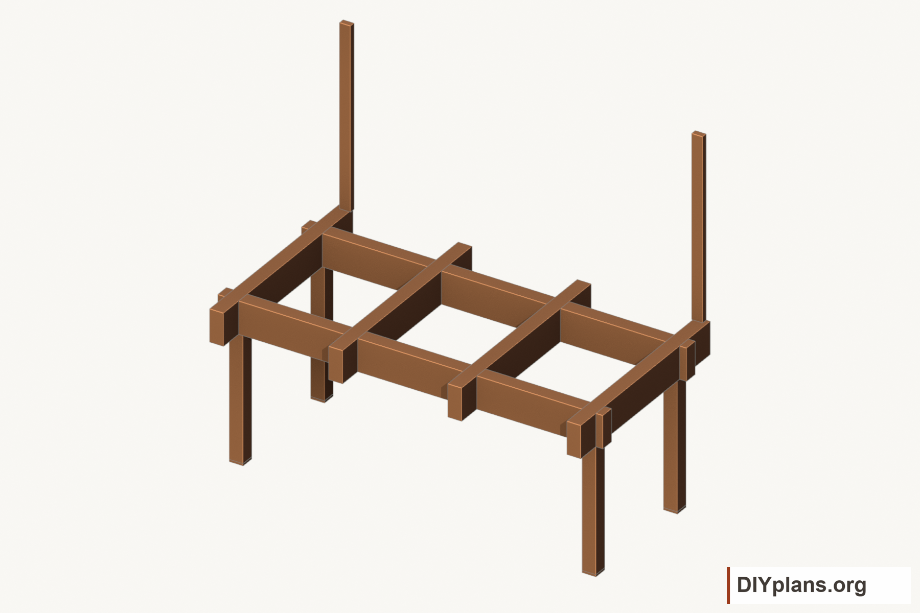
- Cut the sixteen nominal 4x4 posts, actual 3 1/2 x 3 1/2 in, to the post schedule, checking each length against the actual sloped floor. Seat the posts on the selected load-bearing, non-absorbent feet with the timber at least 1 in above the tile. Adjust each post cut for the actual foot height so the finished beam and seat elevations stay as drawn.
- Bear the 2 3/8 x 5 1/2 in front beams directly on the posts. Secure each post-to-beam joint against movement with the selected ties or joinery.
- Fit nominal 2x4 seat joists, actual 1 1/2 x 3 1/2 in, at the scheduled positions, no more than 17 11/16 in apart. Bear them on the front beams and rear ledgers, with their tops 1 1/8 in below the finished seating. Fit the frame to the actual seat-board thickness.
- Keep the tall posts between the lower joists. Keep the two lower rear posts outside the central cleaning opening.
Check: Every front beam bears on its posts, the frame is secured and the cleaning opening stays clear.
14 Fit the U-shaped cedar seats
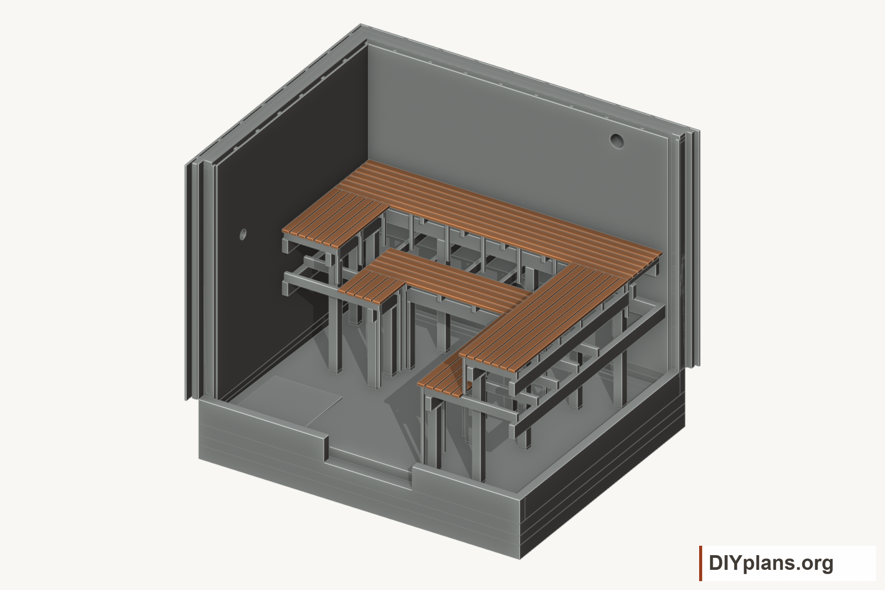
- Fit the 1 1/8 in clear cedar upper seating at 55 1/8 in and the lower seating at 37 3/8 in above the front floor datum. Keep the upper benches 23 5/8 in deep and the exposed lower benches 17 11/16 in deep.
- Run the rear boards across the room and the return boards front-to-back. Keep the 9/16 in seat joints and 1 in wall gaps open.
- Fasten the boards from below and round the contact edges. Run the right reclining return to its front wall gap. Omit facing at that wall-adjacent end.
Check: Both seating heights, bench depths, board joints and wall gaps match the plan.
15 Close the cedar bench faces
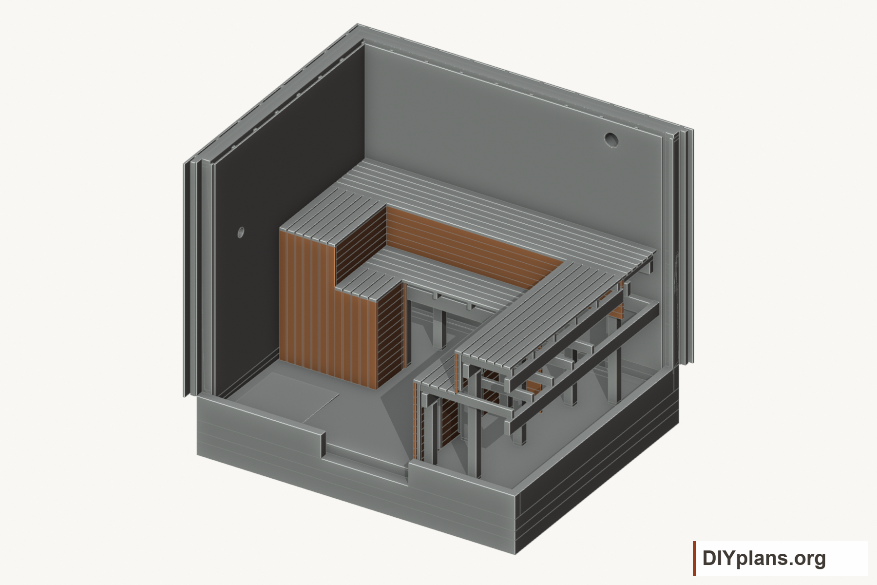
- Run horizontal face boards parallel to the long seating boards. At the exposed left return ends, align vertical waterfall boards with the seat boards.
- Use overlapping or interlocking edges to conceal movement gaps without leaving open slots. Keep the finished faces within the 1 1/16 in envelope; do not glue a wide panel across the grain.
- Scribe the lower faces to finish 1/2 in above the sloping floor. End the upper faces at the lower seating and retain the connected space behind them.
- Fix the boards from behind to the backing cleats. Keep the central rear panel separate so it can come out with the lowest step.
Check: Faces are closed, board direction matches the seating and the lower edge follows the floor.
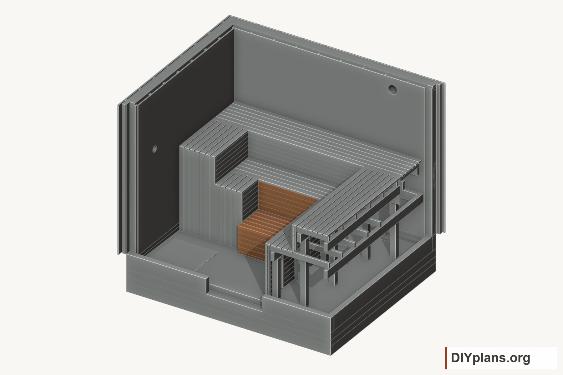
Play movementStop movement

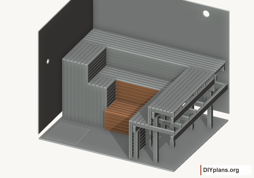
16 Fit the removable cleaning step
- Select sauna-compatible concealed positive retainers that release without tools and prevent movement during use. Allow access to both retainers beneath the removable top.
- Build the independent lowest seat with its attached rear access panel and floor pads. Half-lap the crossing frame members as shown in the native model.
- Fit the seat top at 17 11/16 in above the front floor datum. Fit the attached rear panel below the actual underside of the lower seat, leaving at least 1/8 in clear at the top. Trim the top cross-joists behind the front facing.
- Fit the two selected retainers beneath the removable top.
- Fit the removable module to leave at least 1/4 in clear at each side and 1/8 in above its rear panel. Slide it at least 2 in forward along the sloping floor before lifting it at least 1 in and drawing it clear. Fit the module to the actual opening; use the clearances rather than subtracting rounded schedule dimensions.
- Check access to the rear drain and low extract pickup. The space below the rear bearing beam is about 28 5/8 in high. Reinstall the module and engage both retainers before use.
Check: The step releases, clears the rear panel and locks securely when reinstalled.
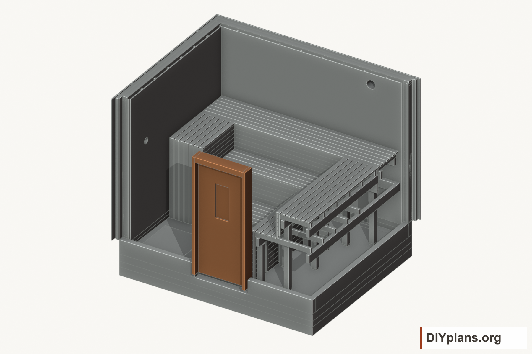
17 Fit the outward-opening door
- Install the selected insulated timber sauna door into its flashed rough opening. Adjust the frame, stops and shims to its instructions.
- Use the 9 13/16 x 23 5/8 in safety-glass vision panel allowance and an outward-opening leaf. Keep the exterior landing clear of the entire swing.
- Check the actual net opening after hardware is fitted. The model's 33 7/16 in leaf envelope is not a certified 33 7/16 in clear passage.
Check: The door opens outward over a clear landing and operates freely.
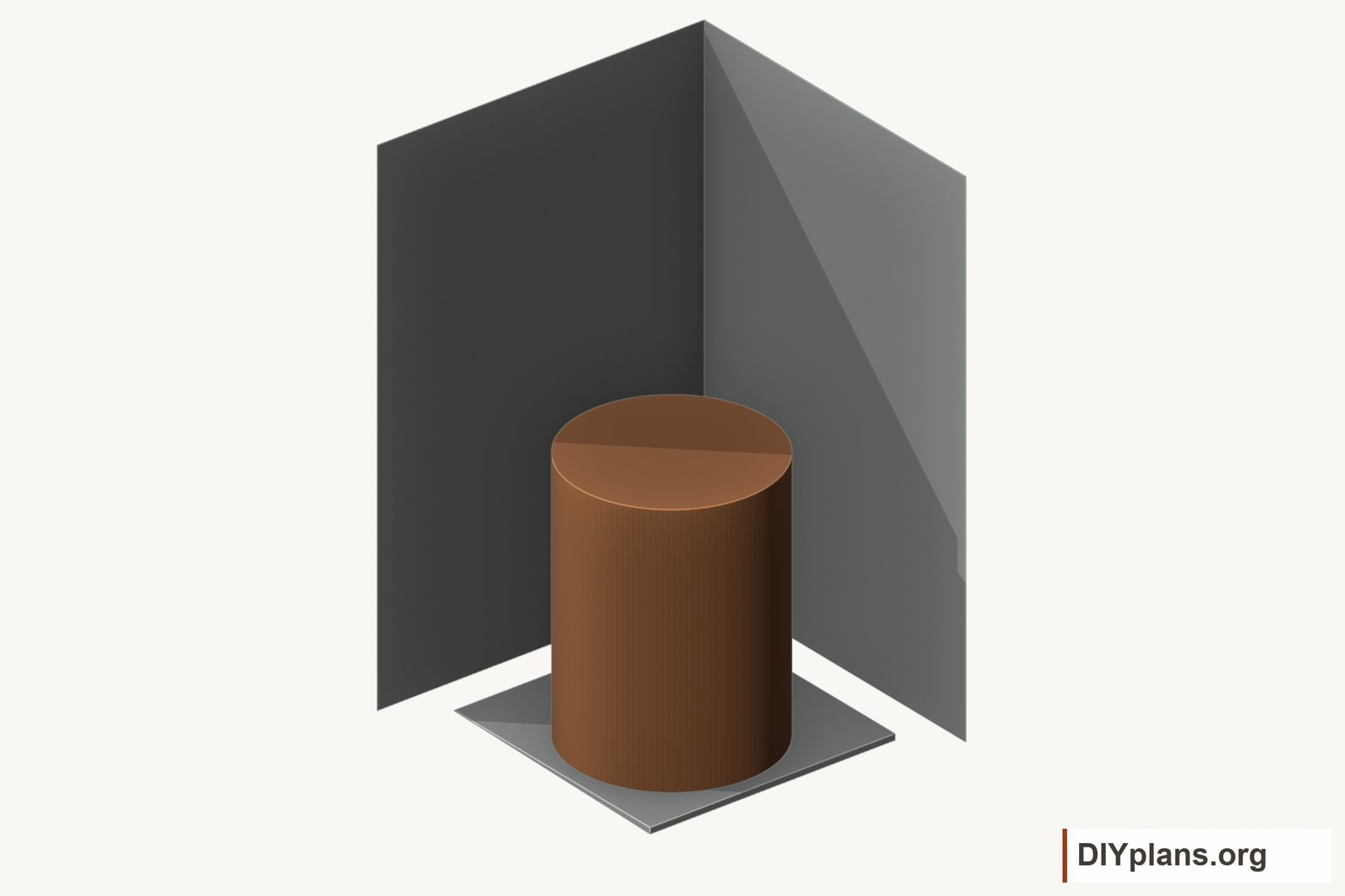
18 Fit the metal corner shields
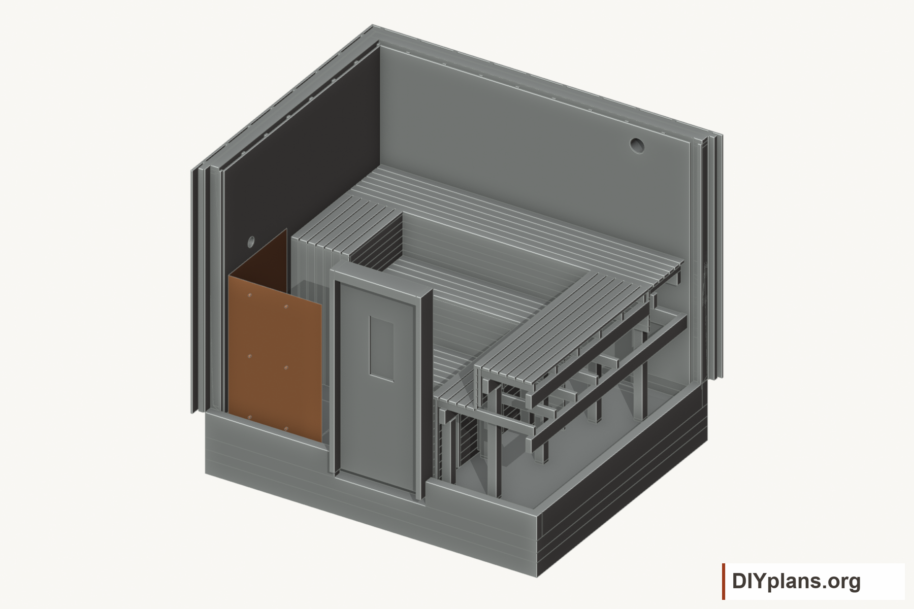
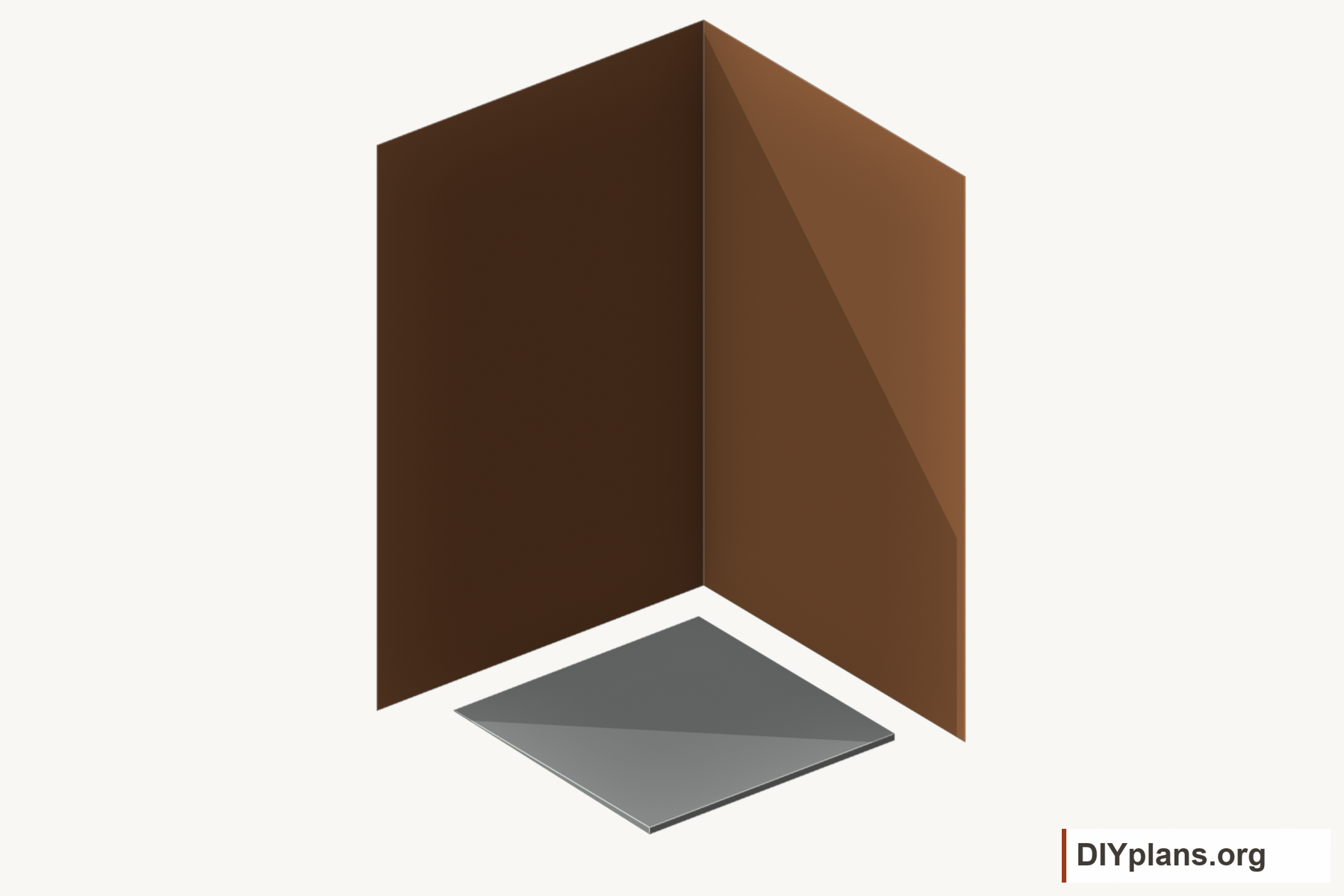
- Select stainless fixings and formed edges for the panels. Have exposed edges deburred and hemmed, and use slotted holes or another fixing arrangement that permits thermal expansion. Seal any foil penetrations with the compatible sauna system.
- Fit two brushed, uncoated 304 stainless steel panels on the front-left corner walls. Specify sheet approximately 47.2 mil thick (about 3/64 in) and extend each panel to 39 3/8 in from the corner. Have the fabricator verify the finished thickness and fit before forming the edges.
- Set the lower edges at z=1 in and the top edges at z=60 1/16 in. Use 1 in noncombustible ceramic standoffs to leave an open air path behind both sheets.
- Fix the front panel through standoffs into the studs at x=10 1/16 in and x=25 1/16 in, and the left panel at y=13 7/16 in and y=28 1/4 in. Place fixings at z=5 7/8 in, z=30 1/2 in and z=55 1/8 in; confirm these centers against the actual framing.
- Leave the top, bottom and exposed side ventilation paths open. Do not pack the gap or use combustible battens behind the metal.
- Retain the full heater clearance. These panels provide supplemental heat protection and are not a rated firewall or a certified reduced-clearance system.
Check: Both metal panels are secure, have safe edges and an open 1 in air path, and maintain the full heater clearance.
19 Install and commission the equipment
- Confirm the heater size against the finished room: the HIVE 18 / 240 V serves 636–989 cu ft, and the conservative effective room volume is approximately 828 cu ft after allowing for the glass and all tile upstands.
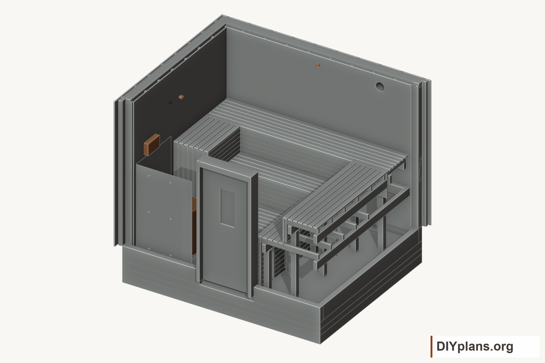
- Have the electrician install the HUUM HIVE 18 / 240 V US and matching UKU 4.2 controls, including the required power extension, to the delivered manuals.
- Set the heater center at x=20 1/16 in, y=20 1/16 in. This gives about 9 1/16 in to the timber walls and 8 in to the metal faces, exceeding the unreduced 7 1/8 in minimum. Position the ceiling safety sensor above that center and locate the rear bench sensor from the delivered manual's ceiling-offset requirement.
- Keep at least 7 1/8 in between the heater body and the front and left combustible walls. Confirm the supplied heater dimensions before setting its final position, and retain the manufacturer's full clearance when fitting the metal panels.
- Account for the absence of a heater guard in this layout. HUUM recommends a safety railing to prevent accidental contact; the specified combustible clearances do not prevent burns from touching the heater.
- Run the fixed low extract duct, about 7 7/8 in in diameter, from the pickup at x=63 3/16 in, y=70 7/8 in, z=18 1/2 in to the rear sleeve. Keep the pickup and cleanout accessible behind the removable panel.
- Fit an adjustable high supply and a closable high drying branch. Keep the drying branch closed while bathing; locate the mechanical fan and balancing controls outside the hot room.
- Keep the rear bench sensor centered at x=63 in, y=102 3/8 in. Set its height from the delivered manual's required ceiling offset; z is approximately 96 7/16 in. With this sensor enabled, the UKU 4.2 US maximum setpoint is 194°F.
- Balance the mechanical ventilation with every closed face and the cleaning step installed. Start near 100 CFM, then measure temperatures at both seating runs, breathing-zone CO2 and drying below the benches. The closed faces differ from an open-underbench layout; heating, ventilation and drying have not been measured in a built sauna.
- Check heater and control operation, door swing, secure seating, step retainers, drainage and cleaning access before the first use.
Check: The heater, controls, measured ventilation, drainage and cleaning access have been checked.
Sources
Original design informed by selected principles in Trumpkin's Notes on Building a Sauna, VTT ventilation research and the cited manufacturer instructions. Clear cedar and closed bench faces are project choices, not a claim of compliance with every recommendation in those sources.