Before you start
- Read all steps and select mounting supplies before cutting.
- Use actual 3/4 x 11 1/4 in cedar and 5/8 in exterior plywood. Measure nominal 1x12 stock before buying.
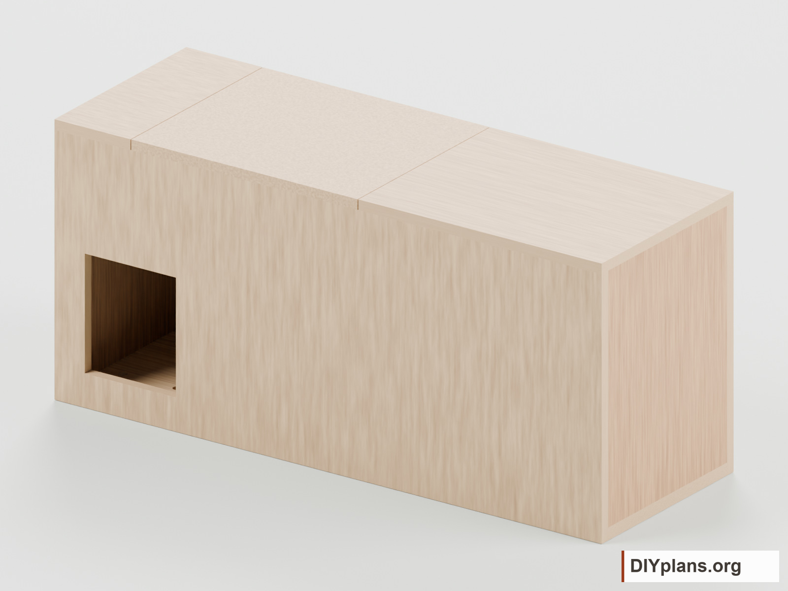
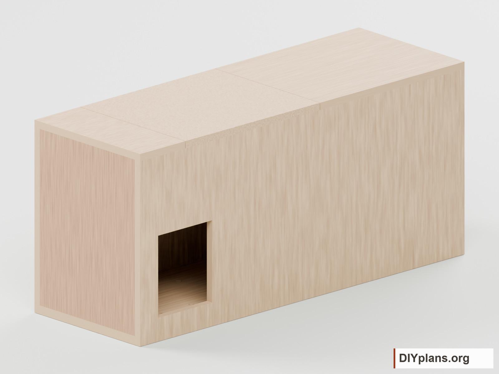
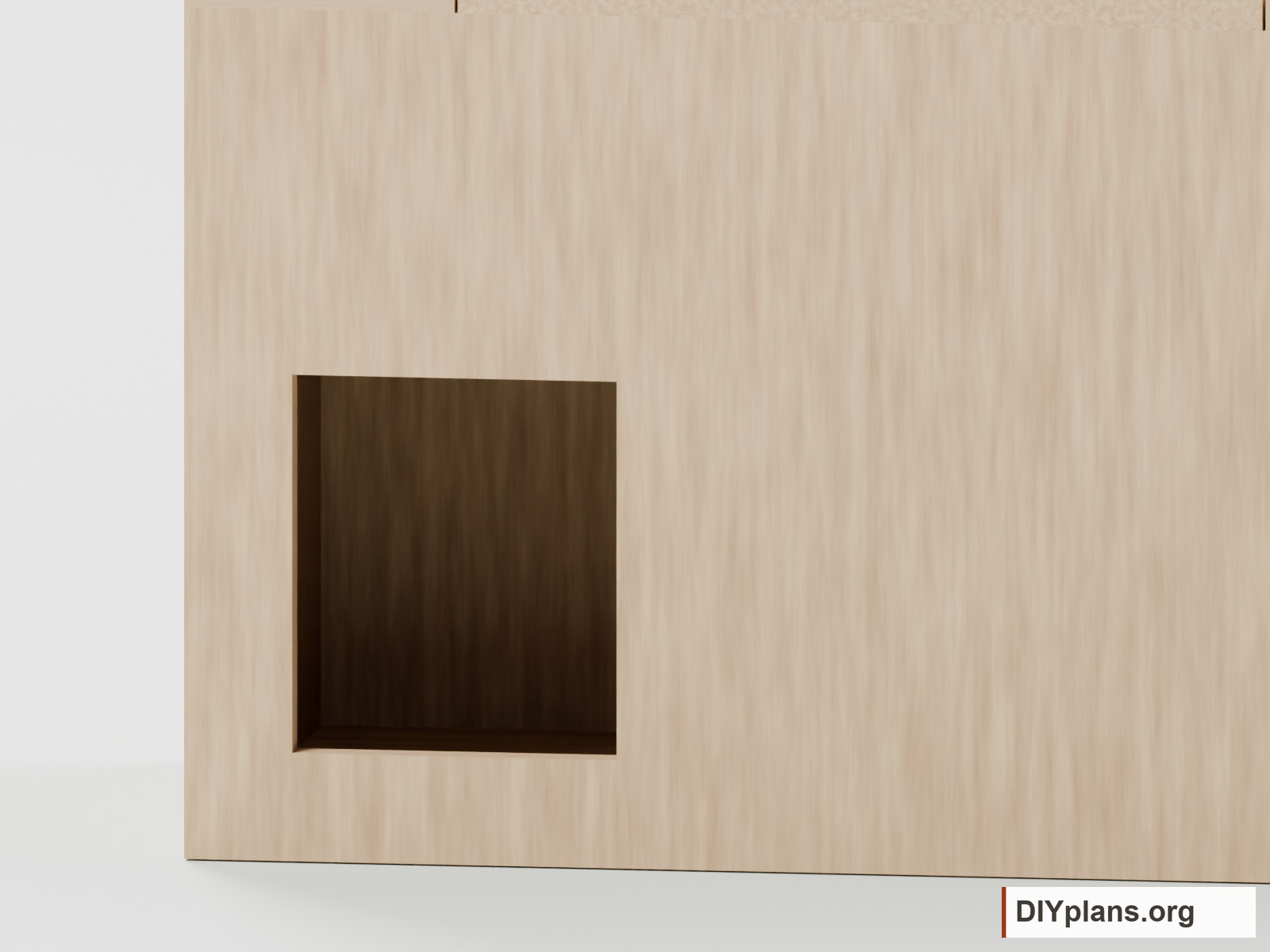
- This box has a 6 x 7 in entrance. These instructions cover an interior cross-beam installation.
- Place the entrance left edge and bottom 2 in from the corresponding front edges.
- Trim the 15 in lid blank to 14 7/8 in to leave 1/16 in at each side. Put the hinge axis at the upper surface of the right roof seam. Hinge size and screw lengths require selection and a dry fit.
- Use twenty 1/2 in drain holes in two rows at 3 and 8 1/4 in from the floor front. Mark ten equally spaced holes in each row between the 2 in and 34 in end marks. Divide the full span evenly instead of accumulating rounded spacings.
Dimensions and opening sizes
- Body widthFinished dimensions of this configuration.
- 36 in
- Outside depthFinished dimensions of this configuration.
- 12 1/2 in
- Closed total heightFinished dimensions of this configuration.
- 16 3/8 in
- Entrance widthFinished dimensions of this configuration.
- 6 in
- Entrance heightFinished dimensions of this configuration.
- 7 in
- Lid blank widthFinished dimensions of this configuration.
- 15 in
Shopping list
| Buy | Material | Stock size |
|---|---|---|
| 1 sheet | Exterior plywood | 4 x 8 ft x 5/8 in |
| 1 board | Untreated cedar | 1x12 x 6 ft; actual 3/4 x 11 1/4 in |
| 1 box of 50 | Exterior wood screws | 1 5/8 in, corrosion resistant |
| 2 | Galvanized exterior hinges | Surface mount; suitable for 5/8 in plywood |
| 1 roll | Galvanized soft tie wire | 16 gauge x 10 ft |
Quantity notes
Full stock units with cutting allowance; retain offcuts for fitting. Hardware counts include an assembly allowance.
- Exterior plywood, 4 x 8 ft x 5/8 in: Two 36 x 15 3/4 panels and one 37 x 12 1/2 roof blank fit across the 48 in width with kerfs.
- Untreated cedar, 1x12 x 6 ft; actual 3/4 x 11 1/4 in: 36 + 15 + 15 in cuts plus 3/8 in total kerf = 66 3/8 in.
- Exterior wood screws, 1 5/8 in, corrosion resistant: 35 assembly screws, plus hinge-specific short screws and two latch screws.
- Galvanized exterior hinges, Surface mount; suitable for 5/8 in plywood: Select screws short enough to avoid projecting into the box. Axis at top of right lid seam.
- Galvanized soft tie wire, 16 gauge x 10 ft: Short doubled tie at two screw eyes or headed screws secures the lid.
Required installation supplies
- Select mounting screws, bolts or anchors for the sound support and actual box weight.
- Select pilot drill diameters for the chosen screws. Keep screw tips within the wood.
Tools & equipment
- Saw suitable for straight cuts and shaped cutouts
- Drill and bits, screwdriver
- Square, tape measure, clamps and abrasive paper
BEFORE YOU BUILD
Use this work at your own risk
No person or organization makes any guarantee or warranty, express or implied, regarding this design, its documentation, digital files, or website views. They are not professional services and do not create an architect-client or other professional-client relationship. No promise is made about accuracy, completeness, reliability, code compliance, or fitness for your project.
Buildings and building projects are complex, and many things can go wrong. You are responsible for checking dimensions and site conditions, choosing suitable materials and methods, obtaining permits, following codes and manufacturer instructions, and getting qualified professional help when needed. To the fullest extent permitted by law, DIYPlans.org disclaims liability for damages resulting from use of this work. Read the FAQ about your responsibilities.
CC CC BY-NC-SA 4.0 InternationalShare and adapt this free design for noncommercial purposes with appropriate credit. Link to the license, indicate changes, and license adaptations under the same terms.
Instructions
01 Lay out the stock
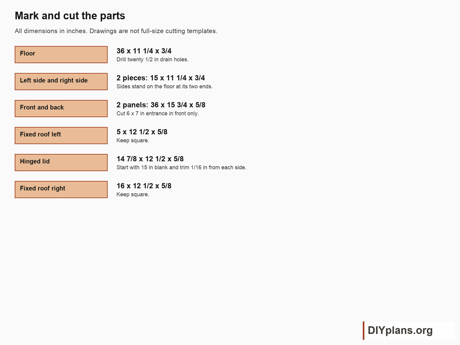
- Mark the plywood front and back at 36 x 15 3/4 in each. Mark a 37 x 12 1/2 in roof blank. Allow 1/8 in between cuts.
- Cut the 37 in roof blank into a 5 in fixed strip, a 15 in lid blank, and a 16 in fixed panel. The extra inch allows three 1/8 in saw cuts and trimming.
- Crosscut the cedar floor at 36 in and two sides at 15 in.
Check: All eight wooden parts are marked and cut with allowance for the roof lid clearances.
02 Cut the entrance and drainage
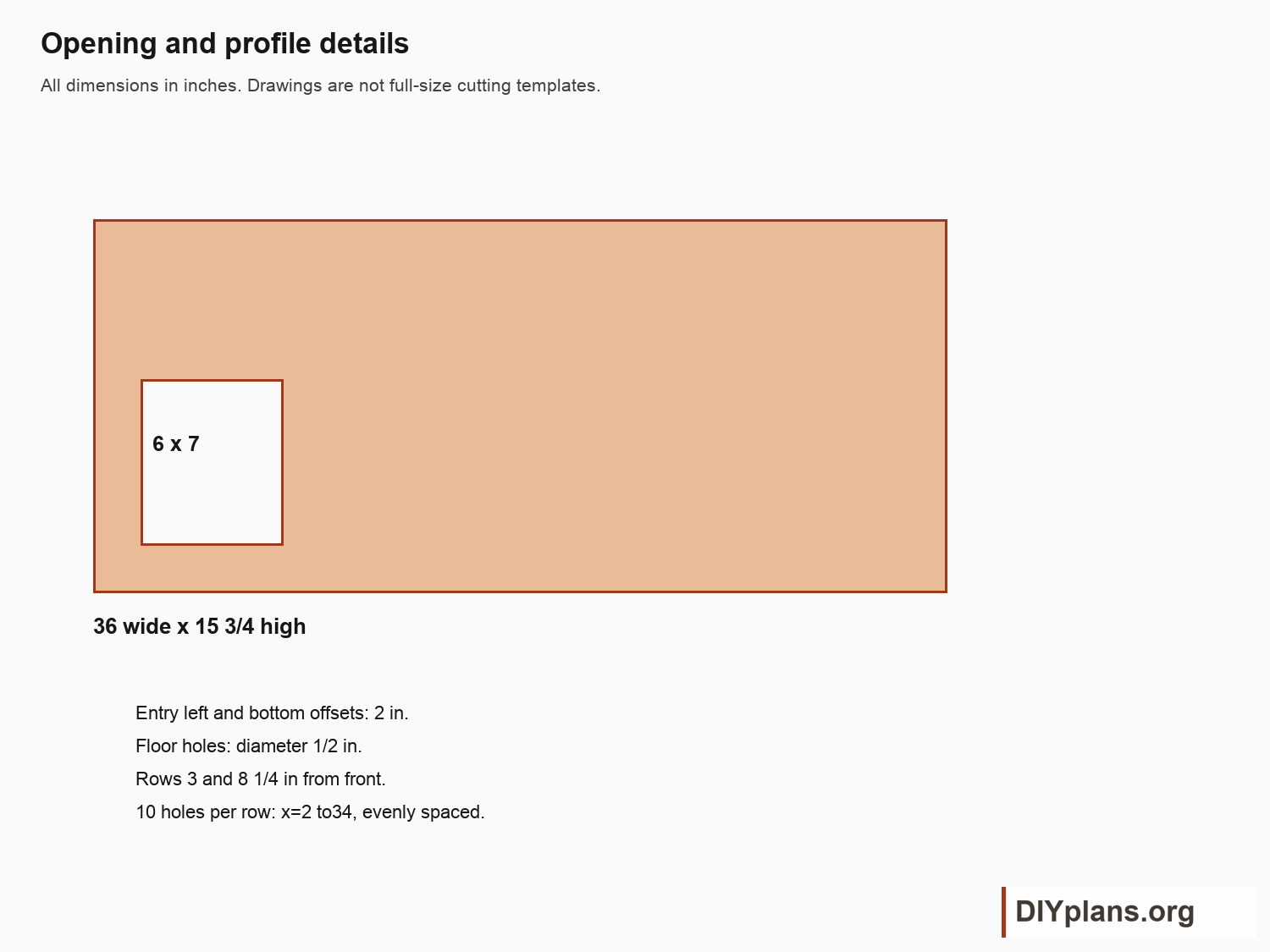
- Mark a 6 in wide x 7 in high rectangle with its left edge and bottom 2 in from the front left and bottom. Drill a starter hole inside the waste, then cut out the entrance.
- Drill twenty 1/2 in holes through the floor. Use two rows 3 and 8 1/4 in from the front edge; locate ten holes equally from 2 to 34 in along each row.
- Sand the entrance and drain-hole edges smooth. Keep the interior unfinished.
Check: The entrance measures 6 x 7 in, has smooth edges, and all twenty floor drain holes are open.
03 Join the floor and end sides
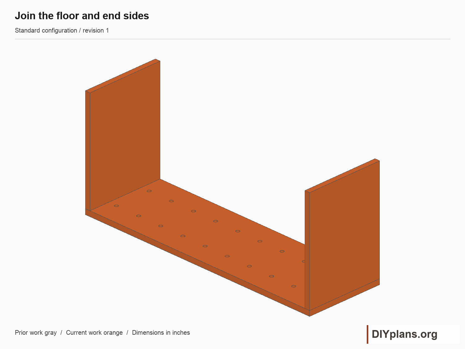
- Stand each 15 in side on the floor with its outer face flush with a 36 in floor end. The side depth is 11 1/4 in.
- Predrill and drive three 1 5/8 in screws up through the floor into each side, spaced across its depth.
- Check both sides stand square. The wall tops should be 15 3/4 in above the floor underside.
Check: Both sides stand square on the floor and their tops are 15 3/4 in above the floor underside.
04 Attach the front and back
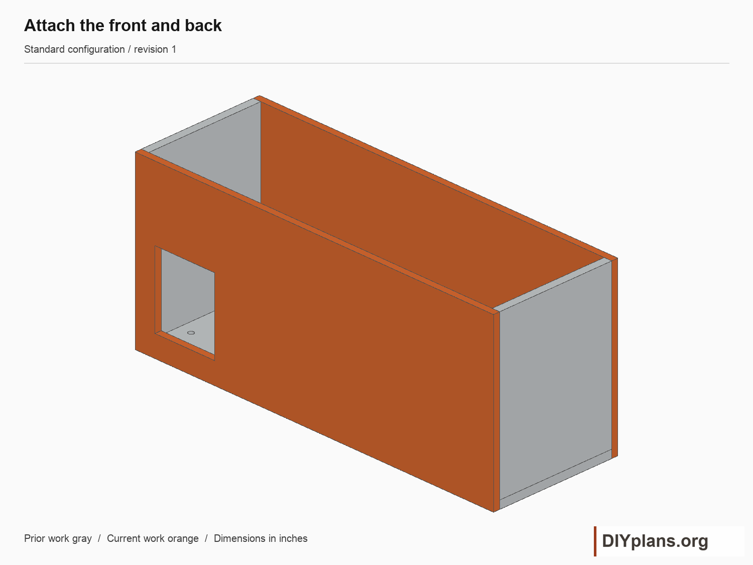
- Fit the 36 x 15 3/4 in front and back over the floor and side edges, keeping their bottoms flush with the floor underside.
- Drive four screws into the floor edge and four into each side edge for each panel. Stagger intersecting screws at corners.
- Check the outside depth is 12 1/2 in, and the entrance is on the front left.
Check: The outside depth is 12 1/2 in, the entrance is at the front left, and the panels are square.
05 Secure the fixed roof panels
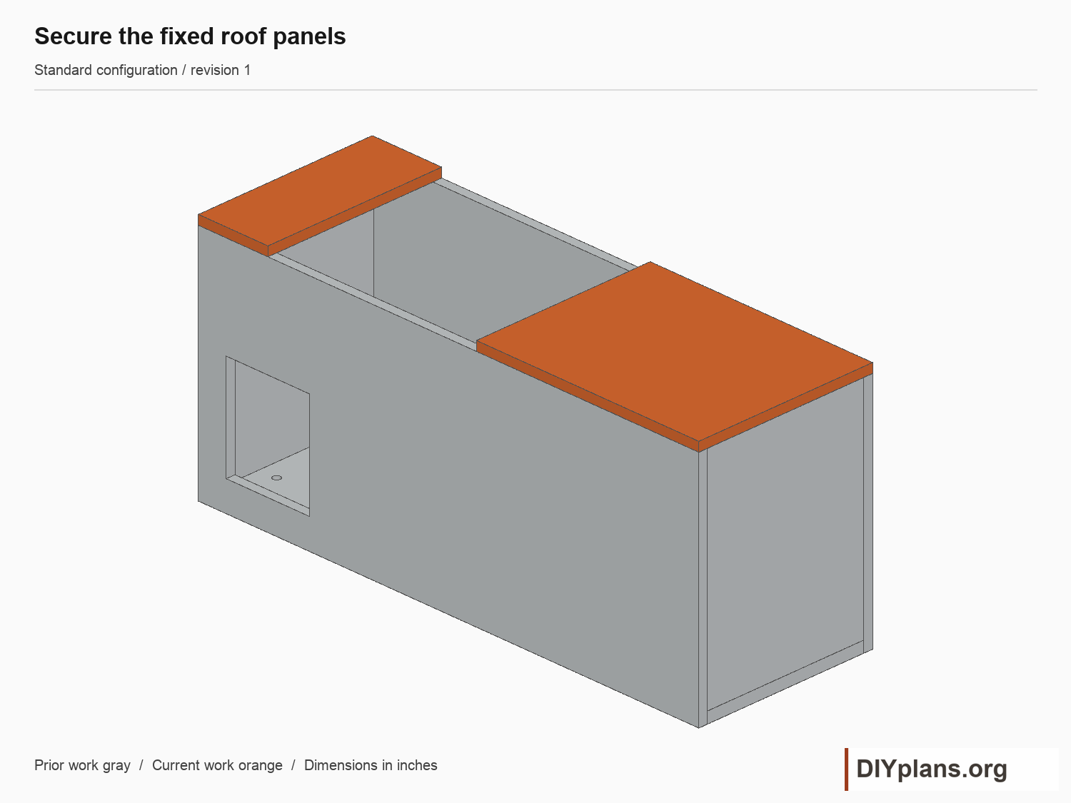
- Place the 5 in strip over the left end and the 16 in panel over the right end. Keep their outside edges flush with the box ends.
- Fix the left strip with two screws and the right panel with three screws into wall edges. Predrill and keep the center 15 in lid opening clear.
- Trim the lid to 14 7/8 in wide and dry-fit it between the fixed panels, with 1/16 in clearance on both sides.
Check: The fixed roof panels are secure and the fitted lid has 1/16 in clearance at each side.
Play movementStop movement

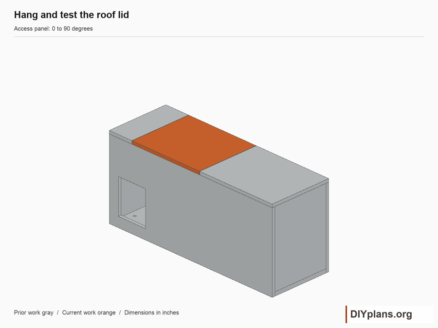
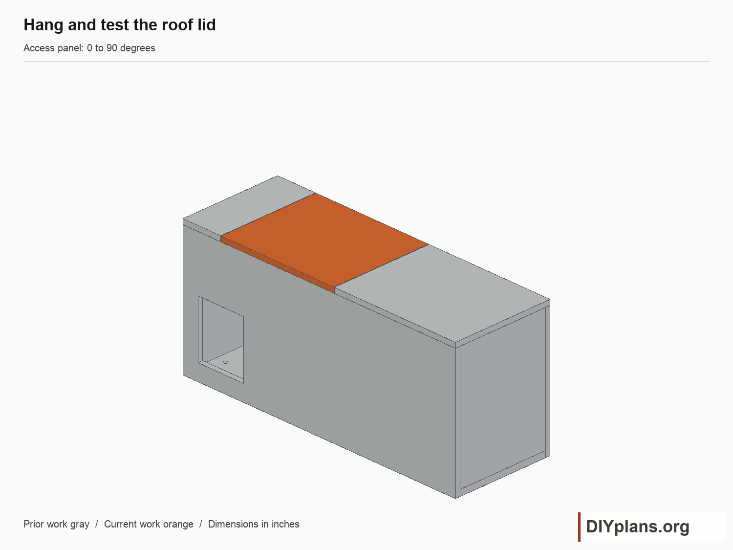
06 Hang and test the roof lid
- Attach two surface hinges along the lid right edge, about 2 1/2 in from the front and rear. Position the hinge pin at the roof top surface over the seam.
- Use the selected short hinge screws without protruding tips. Lift the lid to 90 degrees and check the opening motion shown.
- Fit two latch screws beside the left seam and tie them with doubled wire. Keep sharp wire ends outside and turn them inward.
Check: The lid opens through 90 degrees without binding, closes securely, and has no inward-projecting screws or wire.
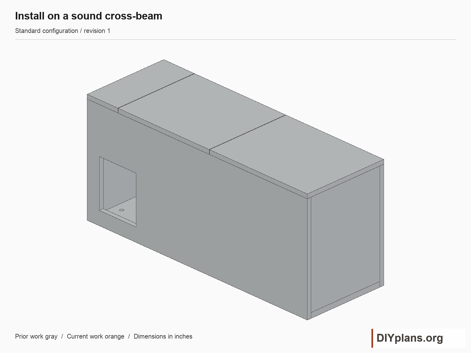
07 Install on a sound cross-beam
- Select a sound interior cross-beam that supports the floor and leaves the entrance facing into the building. Arrange safe access and assistance for installation.
- Choose mounting fasteners for the beam and fix through the floor outside the drain-hole rows. The box and beam connection must resist sliding, tipping and uplift.
- Check the lid remains accessible, the wire latch is closed, and no screw tips protrude into the chamber. Leave the interior bare and follow local wildlife guidance for monitoring an occupied box.
Check: The beam connection prevents sliding, tipping and uplift, and the closed lid remains accessible.
Sources
Functional dimensions informed by the cited Washington Department of Fish and Wildlife woodworking sheet. CAD, instructions, schedules and illustrations authored for DIY Plans.