Before you start
- Design inspiration with dimensioned concept geometry and illustrative connections; no established load, tipping or riding-use rating.
- The base provides a wider geometric support footprint in both axes. No tip-load threshold, impact safety, anchorage capacity or riding-use approval is established.
- Base holes and hardware are an illustrative attachment layout, not selected structural products. Threads, material grade, tightening and connection capacity are unspecified.
- The poles remain body-only geometry. Closed post slots would retain upper rails; the model does not establish a freely falling rail system.
- The 126 in pole blank remains provisional. Flush full-depth ends through 3 1/2 in posts would require 127 in before allowance; neither is a final rail joint.
Dimensions and opening sizes
- Clear opening between postsIllustrated geometry; footprint is a bounding extent, not a capacity rating.
- 120 in
- Post heightIllustrated geometry; footprint is a bounding extent, not a capacity rating.
- 54 in
- Each base, left to rightIllustrated geometry; footprint is a bounding extent, not a capacity rating.
- 36 in
- Each base, front to backIllustrated geometry; footprint is a bounding extent, not a capacity rating.
- 36 in
- Individual arm lengthIllustrated geometry; footprint is a bounding extent, not a capacity rating.
- 19 3/4 in
- Overall assembly lengthIllustrated geometry; footprint is a bounding extent, not a capacity rating.
- 159 1/2 in
- Highest illustrated rail topIllustrated geometry; footprint is a bounding extent, not a capacity rating.
- 48 in
Shopping list
| Buy | Material | Stock size |
|---|---|---|
| 1 board | 4 x 4 lumber | 10 ft |
| 6 | Sound natural poles, 3-4 in diameter | At least 11 ft |
| 2 board | 2 x 6 lumber | 8 ft |
| 8 | Illustrative through bolts | 3/8 in; 7 in under head shown |
| 16 | Illustrative washers | 1 in OD x 1/16 in thick shown |
| 8 | Illustrative nuts | 3/8 in; 5/16 in thick shown |
Quantity notes
Indicative timber allocation and illustrated connector quantities only. Selected hardware products, coatings, ground anchors and installation materials are outside this reference.
- 4 x 4 lumber, 10 ft: Two 54 in post blanks; allow saw kerfs and end trimming.
- Sound natural poles, 3-4 in diameter, At least 11 ft: 126 in provisional blanks. Species, defects and final pole-end geometry are not specified.
- 2 x 6 lumber, 8 ft: Four 19 3/4 in arms per board total 79 in, plus 3/8 in for three interior kerfs; eight arms total.
- Illustrative through bolts, 3/8 in; 7 in under head shown: Generic unthreaded envelopes. Dimensions illustrate the attachment; select actual hardware separately.
- Illustrative washers, 1 in OD x 1/16 in thick shown: Two per bolt; 7/16 in modeled bore. No manufacturer specification or capacity assigned.
- Illustrative nuts, 3/8 in; 5/16 in thick shown: 9/16 in flats in model, no threads. Verify actual thread engagement and compatibility.
Tools & equipment
- FreeCAD for editing the native solid model
- STEP-compatible CAD software for exchange geometry
BEFORE YOU BUILD
Use this work at your own risk
No person or organization makes any guarantee or warranty, express or implied, regarding this design, its documentation, digital files, or website views. They are not professional services and do not create an architect-client or other professional-client relationship. No promise is made about accuracy, completeness, reliability, code compliance, or fitness for your project.
Buildings and building projects are complex, and many things can go wrong. You are responsible for checking dimensions and site conditions, choosing suitable materials and methods, obtaining permits, following codes and manufacturer instructions, and getting qualified professional help when needed. To the fullest extent permitted by law, DIYPlans.org disclaims liability for damages resulting from use of this work. Read the FAQ about your responsibilities.
CC CC BY-NC-SA 4.0 InternationalShare and adapt this free design for noncommercial purposes with appropriate credit. Link to the license, indicate changes, and license adaptations under the same terms.
Instructions
01 Read the four-sided base
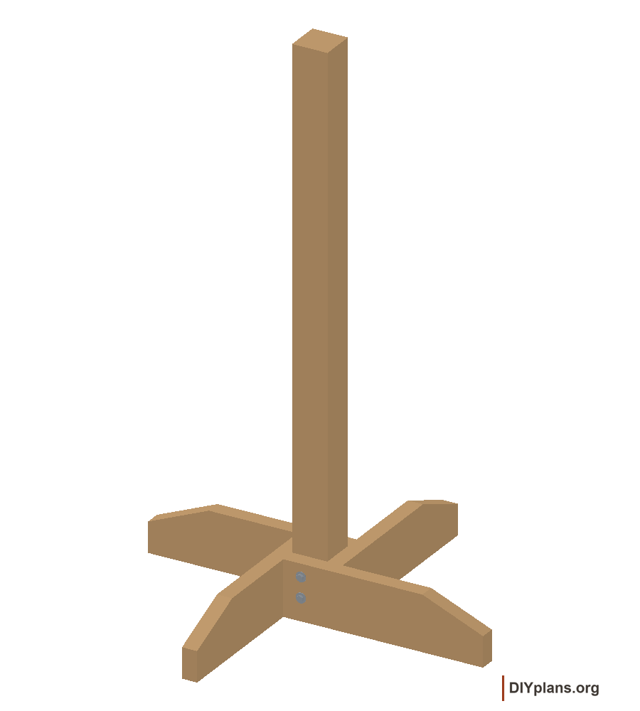
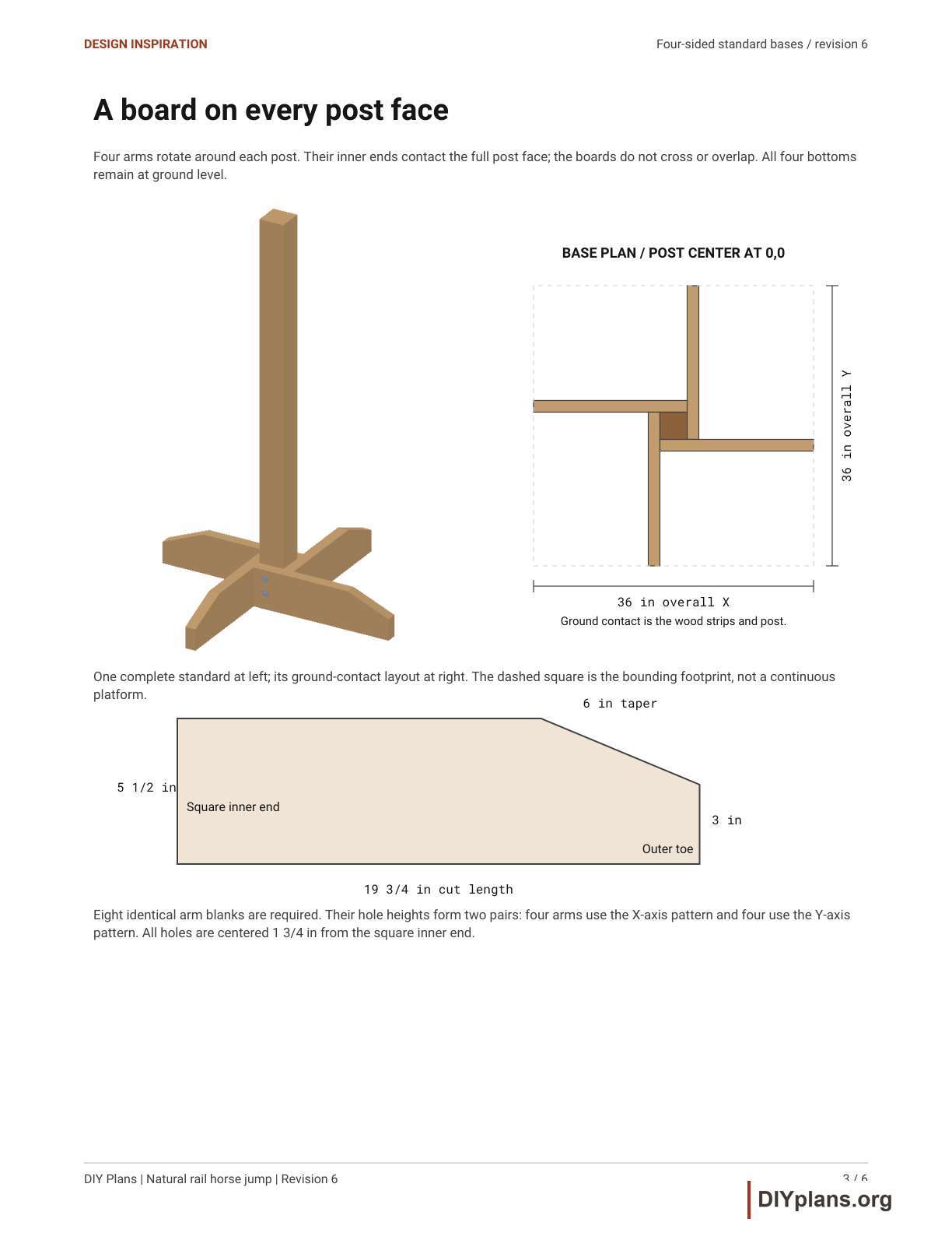
- Each standard has one 19 3/4 in arm on each of its four faces. The arms rotate around the post in a pinwheel, giving a 36 x 36 in bounding footprint without crossing boards. All arm bottoms and the post base share the ground plane.
Check: Find four arms on each standard, with support extending in both horizontal directions.
02 See the standards without poles
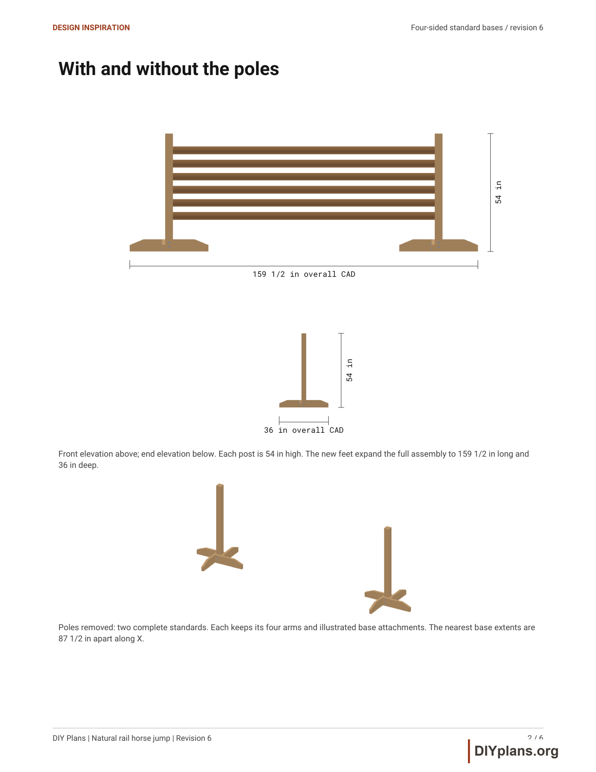
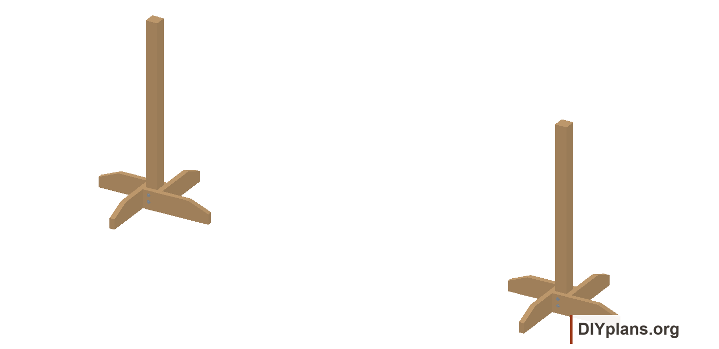
- The poles-removed view shows both complete standards. Their four-arm bases and depicted through-bolt attachments are unchanged by pole removal. Ground contact is the four narrow arm strips and post, not a solid square platform.
Check: Identify the clear gap between the two independent bases and the flat contact beneath every arm.
03 Inspect the illustrated base connections
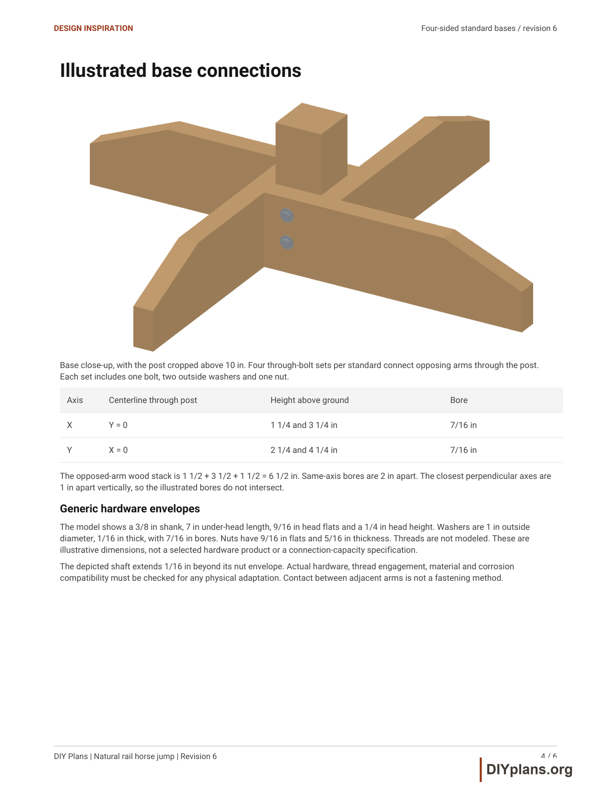
- Each standard has four bolt sets. The X-directed axes are 1 1/4 and 3 1/4 in above ground; the Y-directed axes are 2 1/4 and 4 1/4 in above ground. Each axis passes through two opposed arms and the post, a 6 1/2 in wood stack.
Check: Locate two bores in each arm and check that the perpendicular bore pairs sit at different heights.
04 Compare the unchanged rails
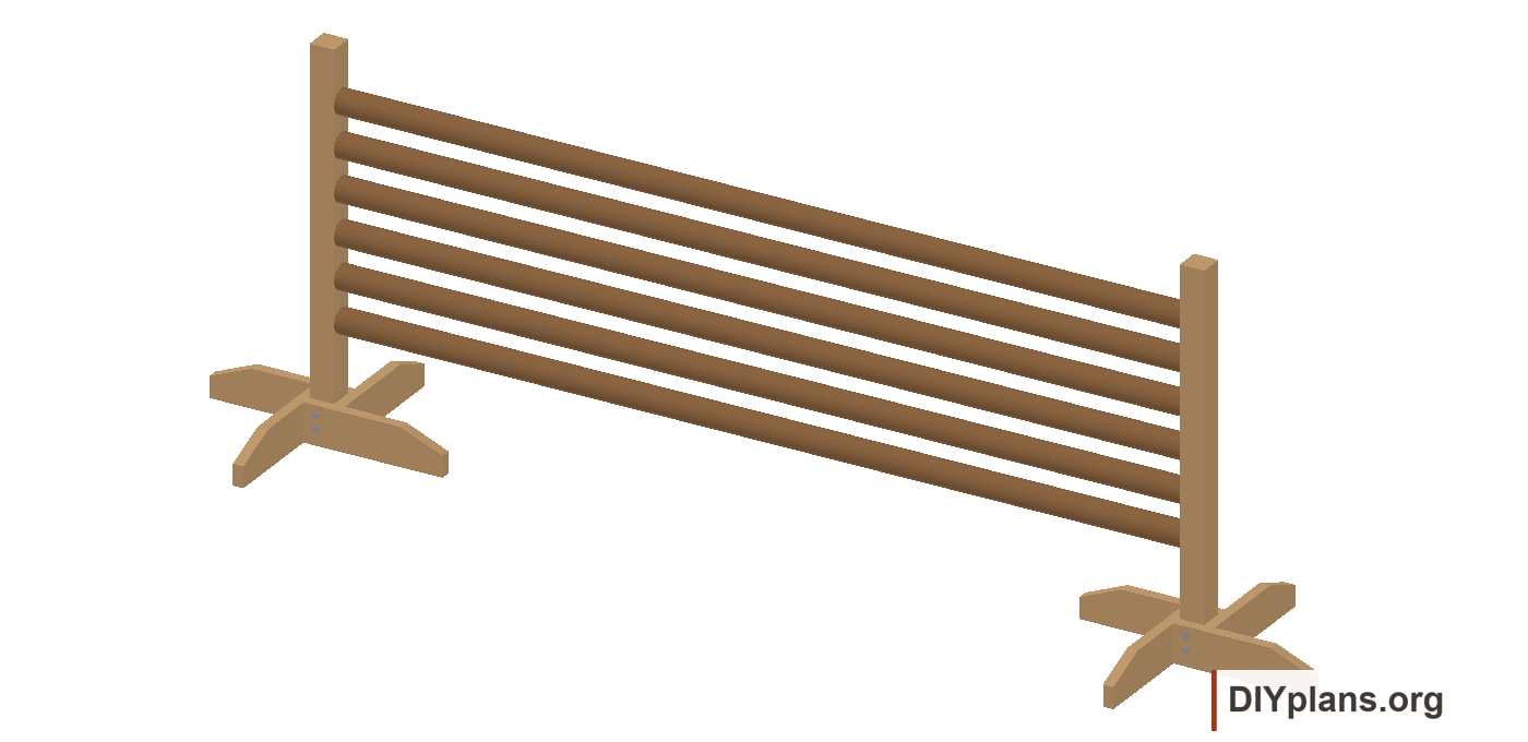
- The six 120 in pole bodies have tops at 18, 24, 30, 36, 42 and 48 in. Uniform 3 1/2 in CAD cylinders represent the 3-4 in natural-pole range. Pole ends, post slots and release hardware are not modeled.
Check: Distinguish the new base connections from the still-unspecified rail connections.
05 Explore a separate variation
- Use the native CAD to study proportions, finishes or base details. Individual solids are editable; the dimension sheet is informational. Update drawings and quantities together if you change the geometry.
Check: Save a separate copy and record the dimensions changed.