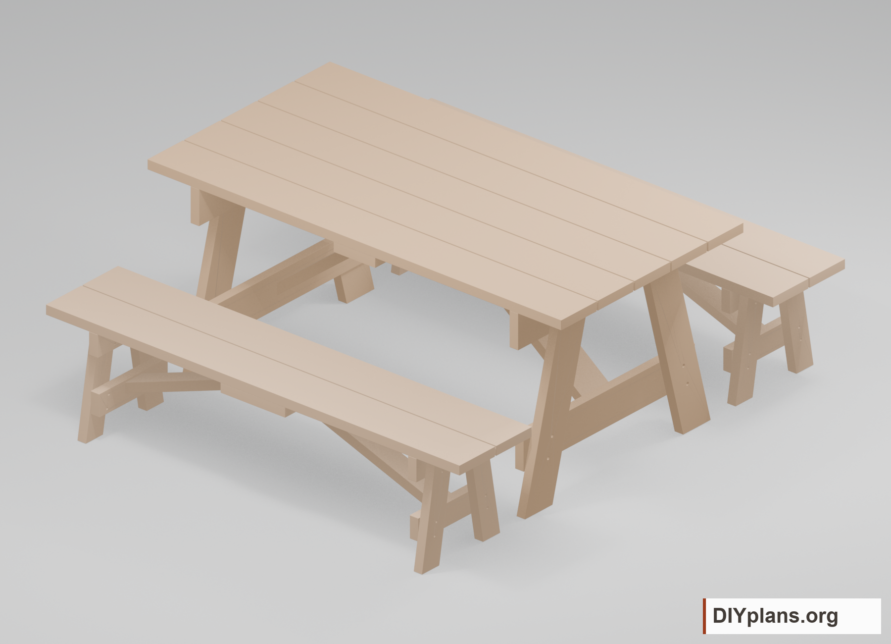
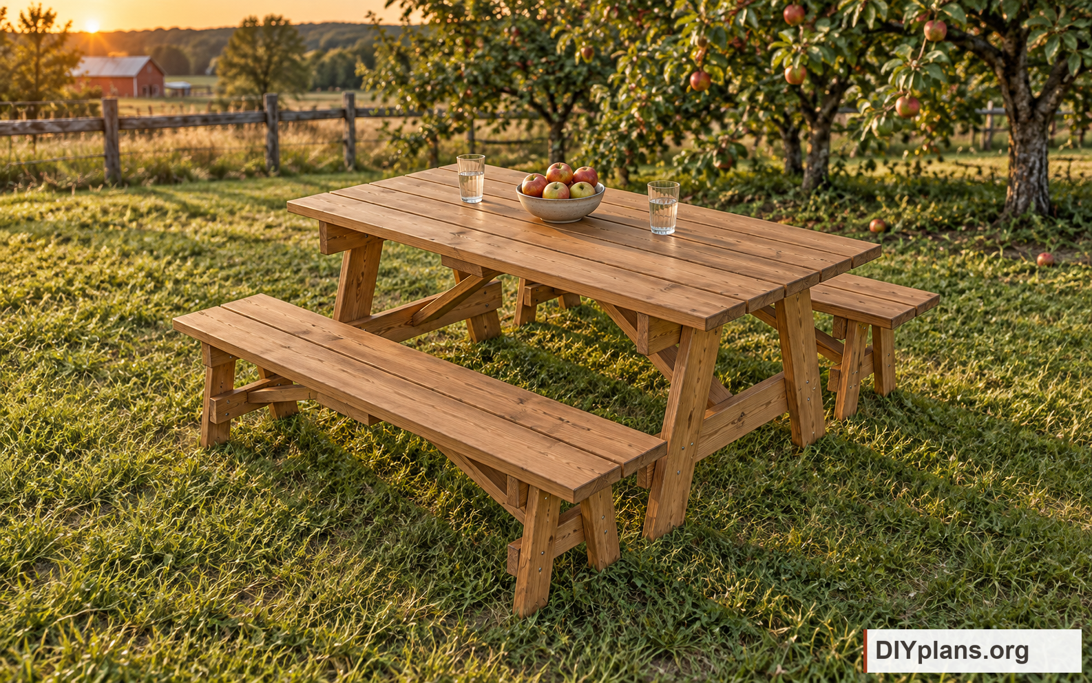
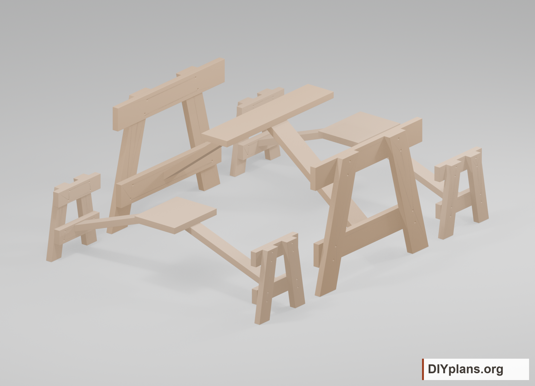
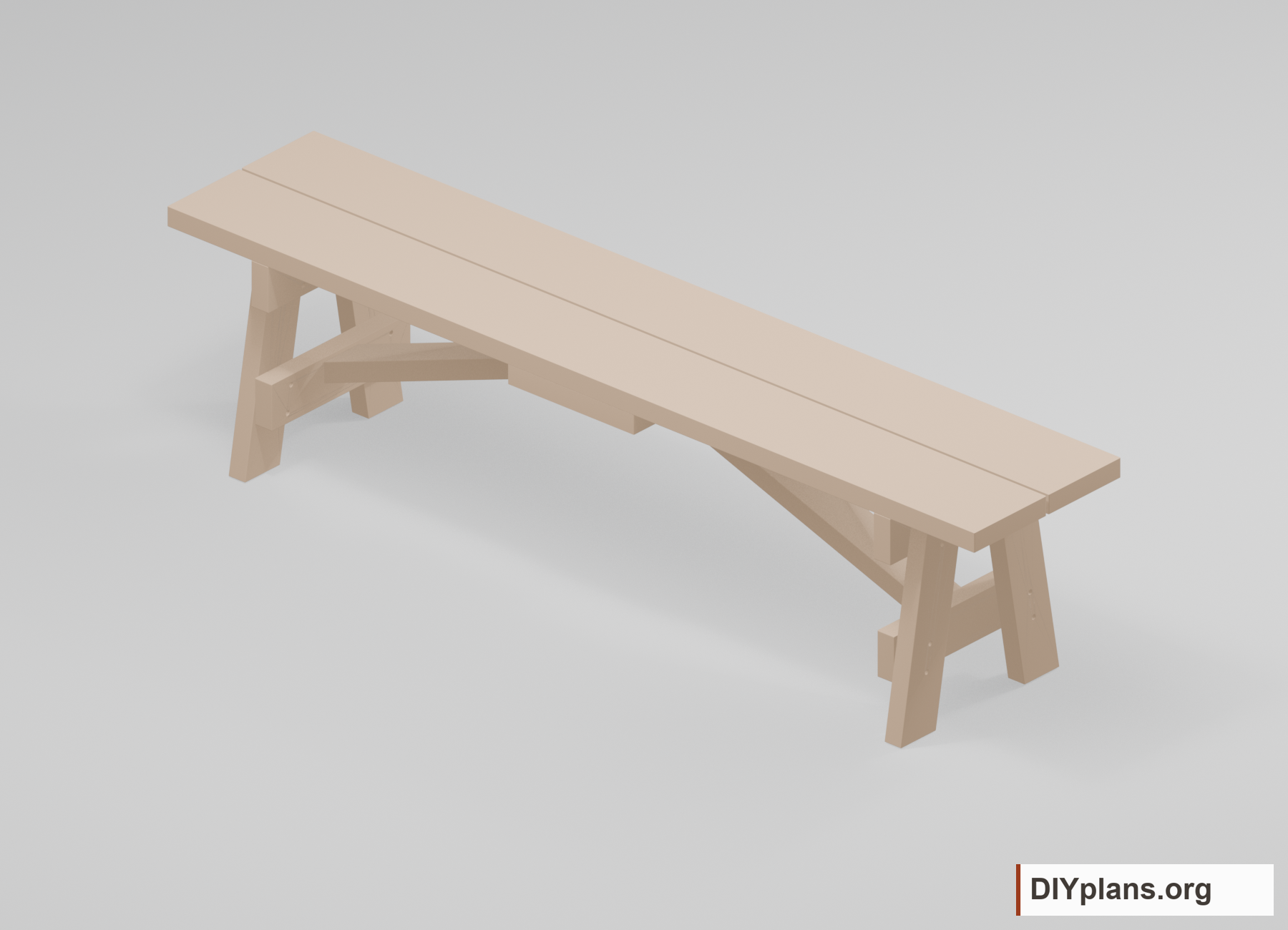
Before you start
- This design has not been built or load-tested. No load rating is assigned.
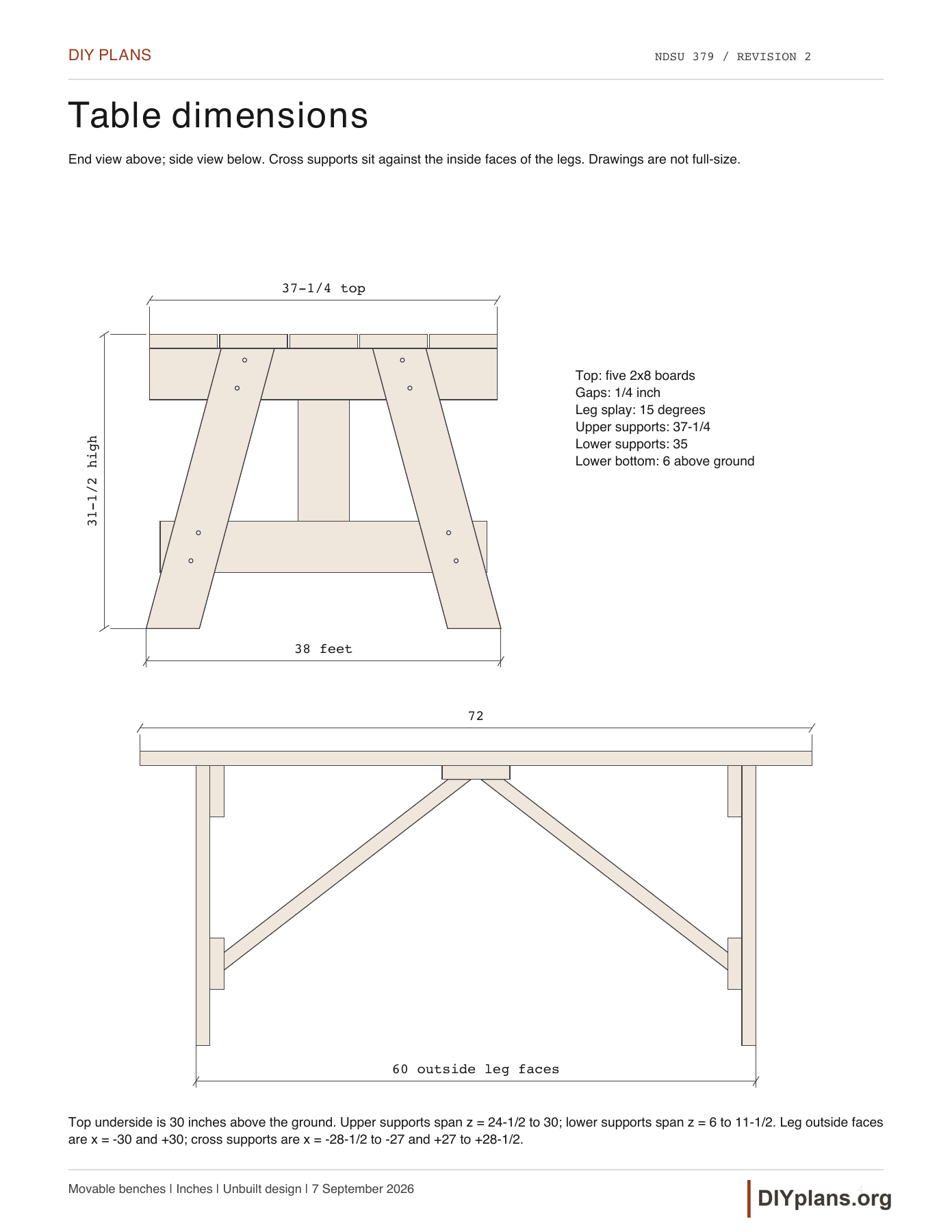
- Measure the finished lumber before cutting. Table height is 31-1/2 inches and seat height is 18 inches.
- Use 1/4-inch gaps between the 2x8 surface boards for a 37-1/4-inch tabletop and 14-3/4-inch seats.
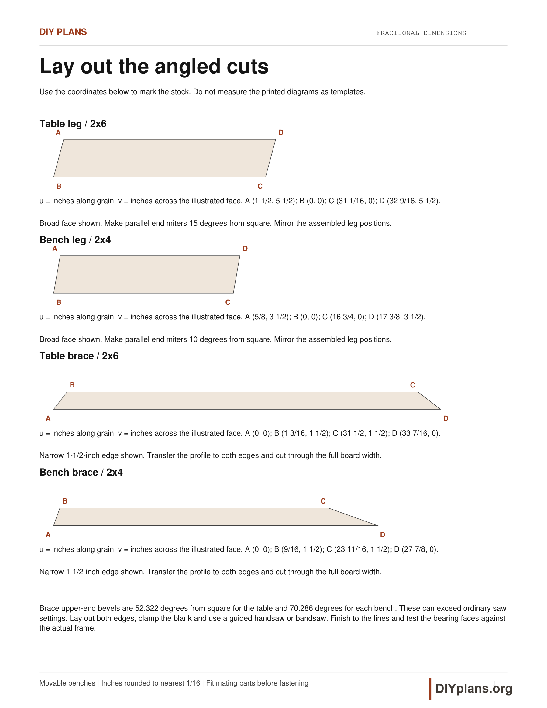
- Use the cut profiles on this page. The steep brace bevels may require a guided handsaw or bandsaw.
Dimensions and opening sizes
- LengthAll top and seat boards.
- 72 in
- Table widthFive actual 7-1/4-inch boards and four 1/4-inch gaps.
- 37 1/4 in
- Table heightFinished tabletop above ground.
- 31 1/2 in
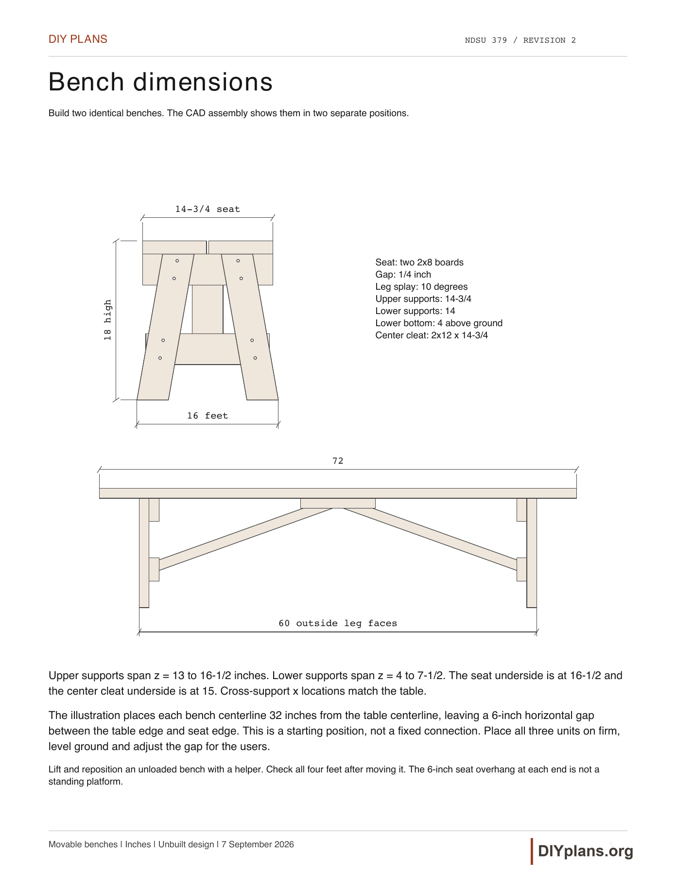
- Seat widthEach bench: two 7-1/4-inch boards and one 1/4-inch gap.
- 14 3/4 in
- Seat heightEach finished seat above ground.
- 18 in
- Table foot spreadAcross the outside feet.
- 38 in
- Bench foot spreadAcross the outside feet of each bench.
- 16 in
- End-frame spacingBetween outside leg faces along the length, not frame centers.
- 60 in
Shopping list
| Buy | Material | Stock size |
|---|---|---|
| 8 boards | 2x8 x 8 ft lumber | 2x8 x 8 ft lumber |
| 1 board | 2x8 x 10 ft lumber | 2x8 x 10 ft lumber |
| 5 boards | 2x6 x 8 ft lumber | 2x6 x 8 ft lumber |
| 4 boards | 2x4 x 8 ft lumber | 2x4 x 8 ft lumber |
| 1 board | 2x12 x 8 ft lumber | 2x12 x 8 ft lumber |
| 16 | 3/8 x 4 in carriage bolts | 3/8 x 4 in carriage bolts |
| 32 | 1/4 x 4 in carriage bolts | 1/4 x 4 in carriage bolts |
| 16 | 3/8 in flat washers | 3/8 in flat washers |
| 32 | 1/4 in flat washers | 1/4 in flat washers |
| 16 | 3/8 in locknuts | 3/8 in locknuts |
| 32 | 1/4 in locknuts | 1/4 in locknuts |
| 1 box of 100 | #10 x 2 1/2 in exterior wood screws | #10 x 2 1/2 in exterior wood screws |
| 1 | Exterior wood finish | Minimum 180 sq ft coverage per coat |
Quantity notes
For one table and two benches. The 19-board layout allows 1/8 inch of saw kerf per cut and 1 inch of end trimming per board. The box of 100 screws includes 22 spares.
- 2x8 x 8 ft lumber, 2x8 x 8 ft lumber: Actual 1 1/2 x 7 1/4 in; eight 72 in top/seat boards
- 2x8 x 10 ft lumber, 2x8 x 10 ft lumber: One 72 in board plus 37 1/4 in table center cleat
- 2x6 x 8 ft lumber, 2x6 x 8 ft lumber: Table legs, supports and diagonal braces; follow the cutting layout.
- 2x4 x 8 ft lumber, 2x4 x 8 ft lumber: Bench frames; five parts per board
- 2x12 x 8 ft lumber, 2x12 x 8 ft lumber: Two 14 3/4 in bench center cleats; a sound 31 in offcut also suffices
- 3/8 x 4 in carriage bolts, 3/8 x 4 in carriage bolts: Exterior-rated; table joints
- 1/4 x 4 in carriage bolts, 1/4 x 4 in carriage bolts: Exterior-rated; bench joints
- 3/8 in flat washers, 3/8 in flat washers: One below each nut
- 1/4 in flat washers, 1/4 in flat washers: One below each nut
- 3/8 in locknuts, 3/8 in locknuts: Match bolt threads
- 1/4 in locknuts, 1/4 in locknuts: Match bolt threads
- #10 x 2 1/2 in exterior wood screws, #10 x 2 1/2 in exterior wood screws: 78 installed; 22 spare; use compatible pilot holes
- Exterior wood finish, Minimum 180 sq ft coverage per coat: At least 180 sq ft of coverage per coat; multiply by chosen product coat count
Tools & equipment
- Tape, square, bevel gauge, pencil and clamps.
- Saw for square and leg-miter cuts; guided handsaw or bandsaw for the steep brace bevels.
- Drill, 7/16-inch and 5/16-inch clearance bits, and pilot bits matched to the selected screw and wood.
- Driver, wrenches, sanding tools, eye and hearing protection.
- Temporary frame supports and a helper for standing and moving the units.
BEFORE YOU BUILD
Use this work at your own risk
No person or organization makes any guarantee or warranty, express or implied, regarding this design, its documentation, digital files, or website views. They are not professional services and do not create an architect-client or other professional-client relationship. No promise is made about accuracy, completeness, reliability, code compliance, or fitness for your project.
Buildings and building projects are complex, and many things can go wrong. You are responsible for checking dimensions and site conditions, choosing suitable materials and methods, obtaining permits, following codes and manufacturer instructions, and getting qualified professional help when needed. To the fullest extent permitted by law, DIYPlans.org disclaims liability for damages resulting from use of this work. Read the FAQ about your responsibilities.
CC CC BY-NC-SA 4.0 InternationalShare and adapt this free design for noncommercial purposes with appropriate credit. Link to the license, indicate changes, and license adaptations under the same terms.
Instructions
01 Prepare and label the stock
- Cut nine 2x8 surface boards to 72 inches. Cut one 2x8 table center cleat to 37-1/4 inches and two 2x12 bench center cleats to 14-3/4 inches. Cut two 2x6 upper table supports to 37-1/4 inches and two lower supports to 35. Cut four 2x4 upper bench supports to 14-3/4 inches and four lower supports to 14. Start table legs from four 33-inch 2x6 blanks, bench legs from eight 17-1/2-inch 2x4 blanks, table braces from two 34-inch 2x6 blanks and bench braces from four 28-1/2-inch 2x4 blanks.
Check: All 42 wooden pieces have labeled blanks matching the cut list and measured stock.
02 Cut the splayed legs
- Use the broad-face coordinates in the cut-profile drawing. Table legs have parallel 15-degree miters, a 30-inch vertical rise, 31 1/16-inch long edges and a 32 9/16-inch stock envelope. Bench legs have parallel 10-degree miters, a 16-1/2-inch rise, 16 3/4-inch long edges and a 17 3/8-inch stock envelope. These are different measurements. Mirror the assembled leg positions so all feet bear level.
Check: Four table legs and eight bench legs match their paired profiles and lie flat at both ends.
03 Lay out and cut the six braces
- Transfer the narrow 1-1/2-inch edge profiles to both sides of each blank, then cut through the full board width. Table brace finished envelopes are 33 7/16 inches; bench brace envelopes are 27 7/8 inches. The broad face runs across its unit. Upper-end bevels are 52.322 degrees from square for the table and 70.286 degrees for each bench. These may exceed ordinary saw adjustment ranges; use a clamped layout and guided handsaw or bandsaw. Finish to the lines and dry-fit the vertical lower and horizontal upper bearing faces.
Check: All six braces match the narrow-edge profiles and dry-fit against their receivers.
04 Lay out the two table end frames
- On a flat surface, set each leg pair to a 38-inch outside foot span. Place upper supports against the inside leg faces, with their bottom edges 24-1/2 inches and top edges 30 inches above the ground datum. Lower supports run from 6 to 11-1/2 inches above ground. Keep the legs and supports clamped while drilling.
Check: Both table frames have a 38- in foot span and supports at the shown heights.
05 Lay out the four bench end frames
- Set each bench leg pair to a 16-inch outside foot span. Upper supports sit against inside leg faces from 13 to 16-1/2 inches above ground. Lower supports run from 4 to 7-1/2 inches. Build two matching end frames per bench.
Check: All four bench frames have a 16- in foot span and supports at the shown heights.
06 Drill and bolt the six end frames
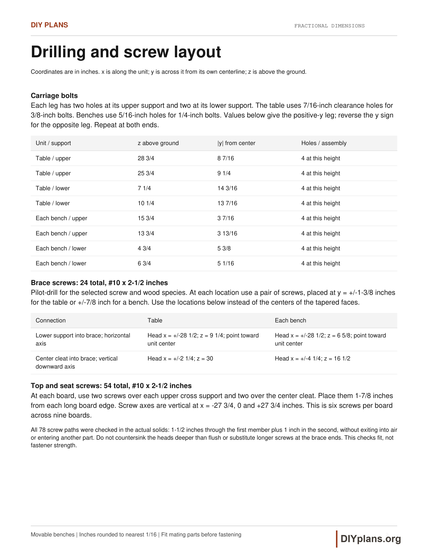
- Drill two holes through each upper leg/support joint and two through each lower joint. Use 7/16-inch clearance holes for the table’s sixteen 3/8 x 4-inch carriage bolts and 5/16-inch holes for the benches’ thirty-two 1/4 x 4-inch bolts. Follow the height and centerline offsets in the drilling drawing, mirrored across each unit. Place heads on outside leg faces and one washer beneath each inside locknut. Seat the heads without crushing the wood and leave joints snug until final squaring.
Check: All 48 carriage bolts pass through clamped matching members with washers and locknuts installed.
07 Stand and temporarily support the three units
- With a helper, set each matching frame pair 60 inches apart between outside leg faces. The supports lie 27 to 28-1/2 inches from either side of the length midpoint; outside leg faces are 30 inches from the midpoint. Temporarily brace each unit with scrap. Center its horizontal cleat across and along the unit; the table cleat underside is 28-1/2 inches high and each bench cleat underside is 15 inches high.
Check: The three units stand temporarily braced with outside leg faces 60 in apart.
08 Fit and fasten all six braces
- Seat each vertical lower brace cut against the inside face of its lower support and its horizontal upper cut beneath the center cleat. Use twenty-four #10 x 2-1/2-inch exterior screws, two at each brace end. For the table, lower screw heads sit 28-1/2 inches from the length midpoint and 9 1/4 inches above ground; drive them toward the center. Upper heads sit 2 1/4 inches from the midpoint and 30 inches above ground; drive them down. Place each pair 1 3/8 inches either side of the width centerline. For each bench, lower heads sit 28-1/2 inches from the length midpoint and 6 5/8 inches above ground; upper heads sit 4 1/4 inches from the midpoint and 16 1/2 inches above ground. Place each pair 7/8 inch either side of the bench centerline. Predrill and keep heads flush. Do not substitute longer screws at the tapered ends.
Check: All six brace ends bear fully;24 screws are seated flush without exposed tips.
09 Install the tabletop and seats
- Set five table boards with four 1/4-inch gaps and two boards on each bench with one 1/4-inch gap. Align the 72-inch ends and center each board on its frames, leaving 6 inches beyond each outer leg face. Compare diagonals and clamp. At each of nine boards, fit two #10 x 2-1/2-inch screws over each upper support and two over the center cleat, 54 screws total. Drive the screws vertically at the length midpoint and 27 3/4 inches to either side. Put the pair 1-7/8 inches from the board’s long edges.
Check: Five tabletop boards and four seat boards have aligned ends,1/4- in gaps and 54 seated screws.
10 Square, tighten and finish
- Set each unit on a known flat surface and check that all four feet bear evenly. Compare diagonals, tighten the 48 locknuts without crushing the lumber, and check bearing faces and screw tips. Remove temporary bracing after the boards secure the frames, then check resistance to hand racking. Ease exposed edges and sand splinters. Apply the selected exterior finish to prepared wood and cut ends, following its coverage, coat and curing directions.
Check: Each unit bears on four feet, has matching diagonals and snug joints without crushed wood.
11 Place and maintain the movable benches
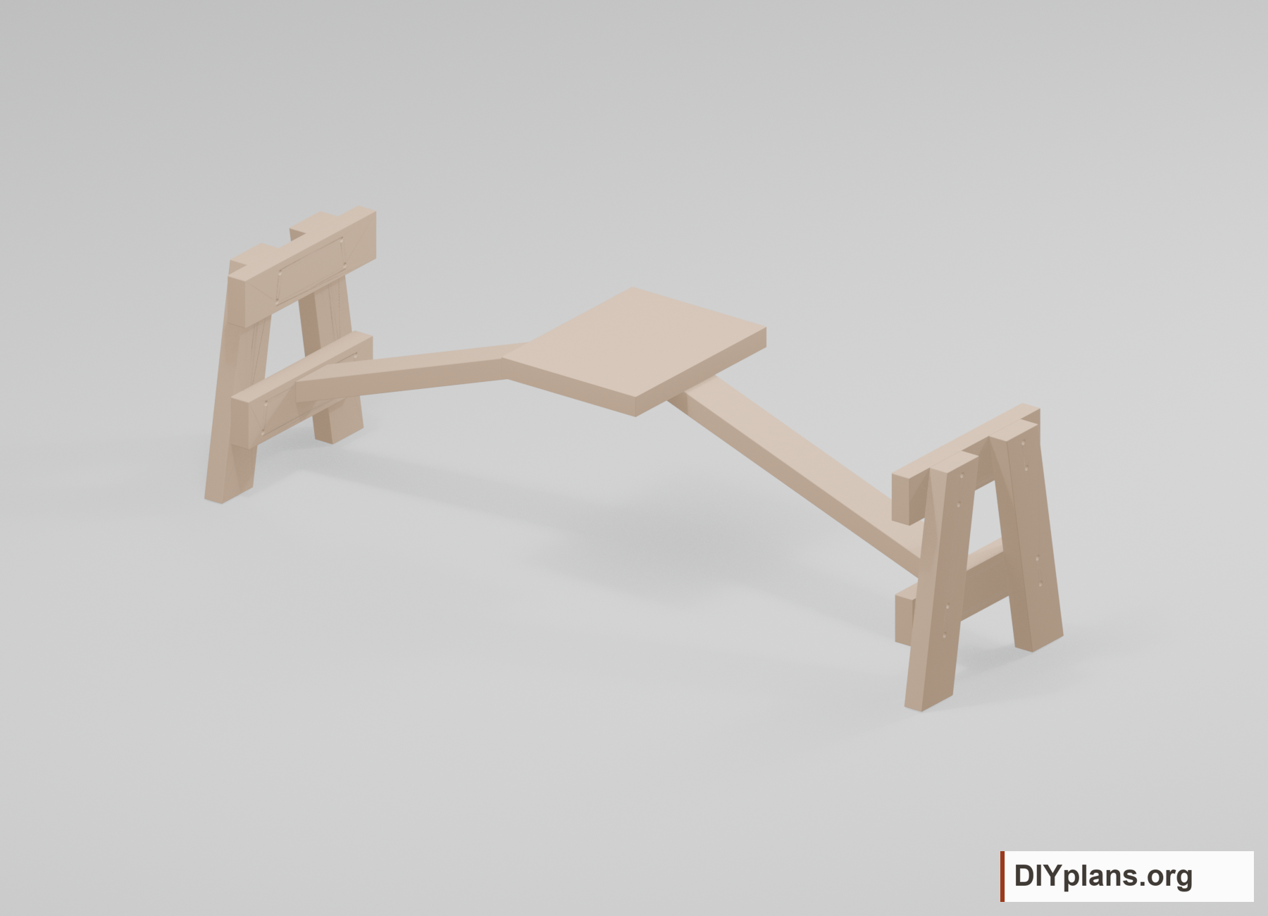
- The illustration starts each bench centerline 32 inches from the table centerline, leaving 6 inches horizontally between the table and seat edges. Adjust this spacing for the users on firm, level ground. Lift an unloaded bench with a helper; check all four feet after moving it. The benches are independent, not folding or wheeled, and are not designed to slide beneath the table. Do not use the 6-inch end overhang as a standing platform. Recheck and tighten joints after the wood settles and seasonally; replace damaged parts before use.
Check: Both unloaded benches sit on firm level ground; joints and fasteners are accessible for reinspection.
Sources
Adapted by DIY Plans from NDSU Extension Plan 379-1-2, Agricultural Engineering Department, drawing initials M.S. Redistribution requires attribution, noncommercial use and similar terms.