BEFORE YOU BUILD
Use this work at your own risk
These files have not been checked for accuracy, safety, structural adequacy, or building-code compliance. They may contain serious errors and are not construction-ready. Obtain independent qualified design and review before building.
No person or organization makes any guarantee or warranty, express or implied, regarding this design, its documentation, digital files, or website views. They are not professional services and do not create an architect-client or other professional-client relationship. No promise is made about accuracy, completeness, reliability, code compliance, or fitness for your project.
Buildings and building projects are complex, and many things can go wrong. You are responsible for checking dimensions and site conditions, choosing suitable materials and methods, obtaining permits, following codes and manufacturer instructions, and getting qualified professional help when needed. To the fullest extent permitted by law, DIYPlans.org disclaims liability for damages resulting from use of this work. Read the FAQ about your responsibilities.
Instructions
Step 1 Confirm dimensions and installation details
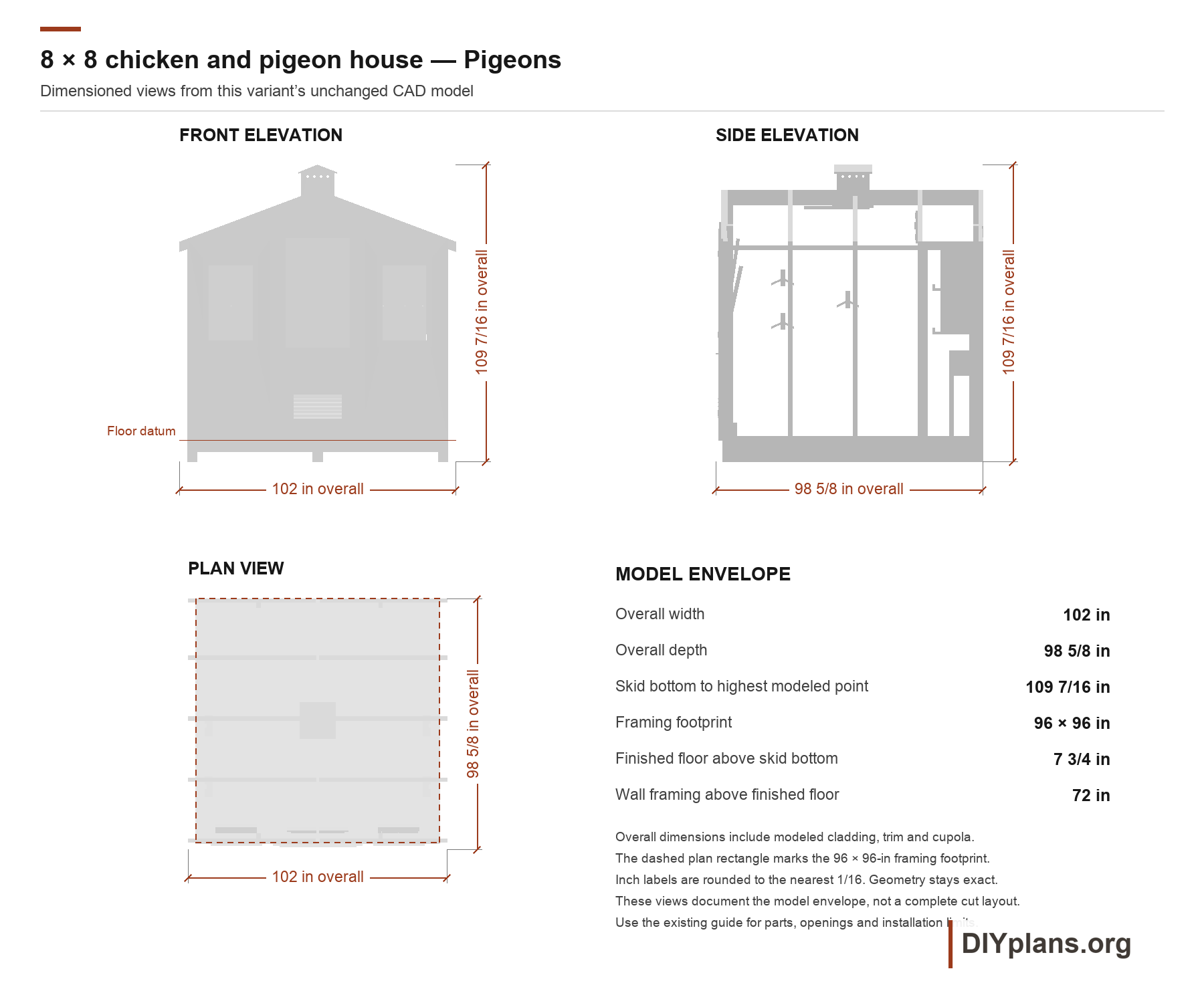
- Confirm the proposed openings and interior sizes before ordering or cutting. The house has an 8×8-foot footprint, walls 6 feet above the floor and an 18-inch roof rise. Complete the structural, weatherproofing and equipment details for the intended site.
Check: Confirm the 96 x 96 in framing footprint, 72 in wall height and 18 in roof rise against the proposed site layout; identify the site-specific details that remain to be designed.
Step 2 Lay out the three skids
- Set out three nominal 4×4 pressure-treated skids running front to rear over a level foundation. Their left edges are 0, 46¼ and 92½ inches across the 96-inch footprint. Ground preparation and anchorage still need to be specified for the site.
Check: Check the three skid left edges at 0, 46 1/4 and 92 1/2 in across the 96 in footprint; confirm the site foundation and anchorage details before setting the skids.
Step 3 Assemble the floor frame and plywood deck
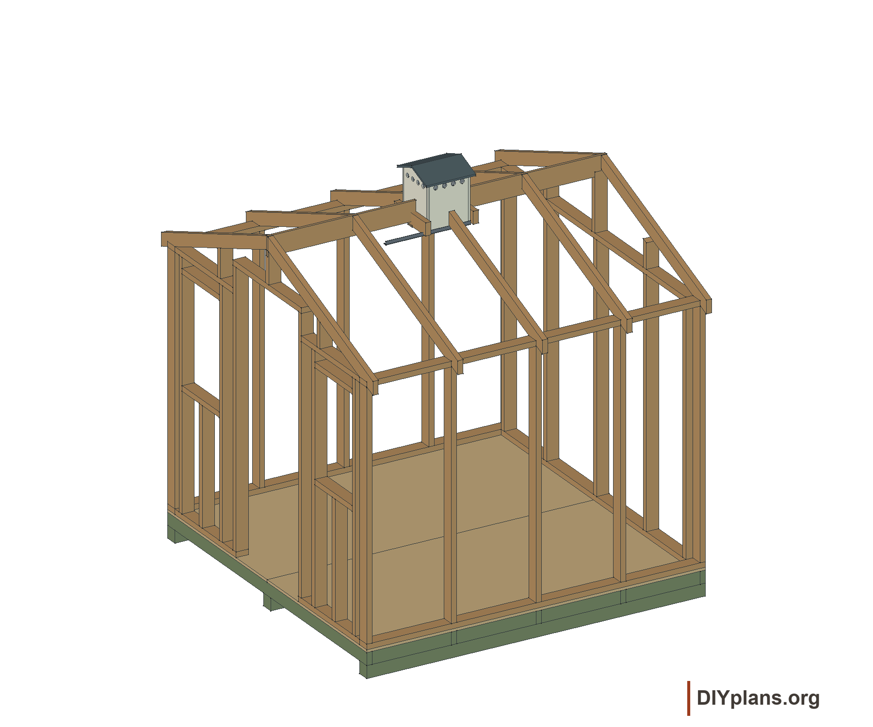
- Use nominal 2×4 pressure-treated joists and ¾-inch plywood flooring. The layout has five 96-inch cross joists, two 93-inch side rims and two nominal 4×8 floor panels. The skids and joists are each 3½ inches deep, giving 7¾ inches from skid bottom to finished floor. The proposed joist spacing is about 24 inches; confirm panel seams, support and fastening before construction.
Check: Check five 96 in cross joists, two 93 in side rims and the 7 3/4 in skid-bottom-to-floor height; confirm supported panel seams and fastening before assembly.
Step 4 Frame the walls to 6 feet above the floor
- Use nominal 2×4 framing with studs at 24-inch spacing. Single 1½-inch bottom and top plates surround 69-inch ordinary studs, placing the wall top 72 inches above the floor. Fit the rear wall between the side walls and keep the framed footprint 96×96 inches. Specify temporary and permanent bracing and connections before construction.
Check: Check the framed footprint is 96 x 96 in and the wall top is 72 in above the floor; confirm the bracing and connection details before construction.
Step 5 Lay out the door and screened windows
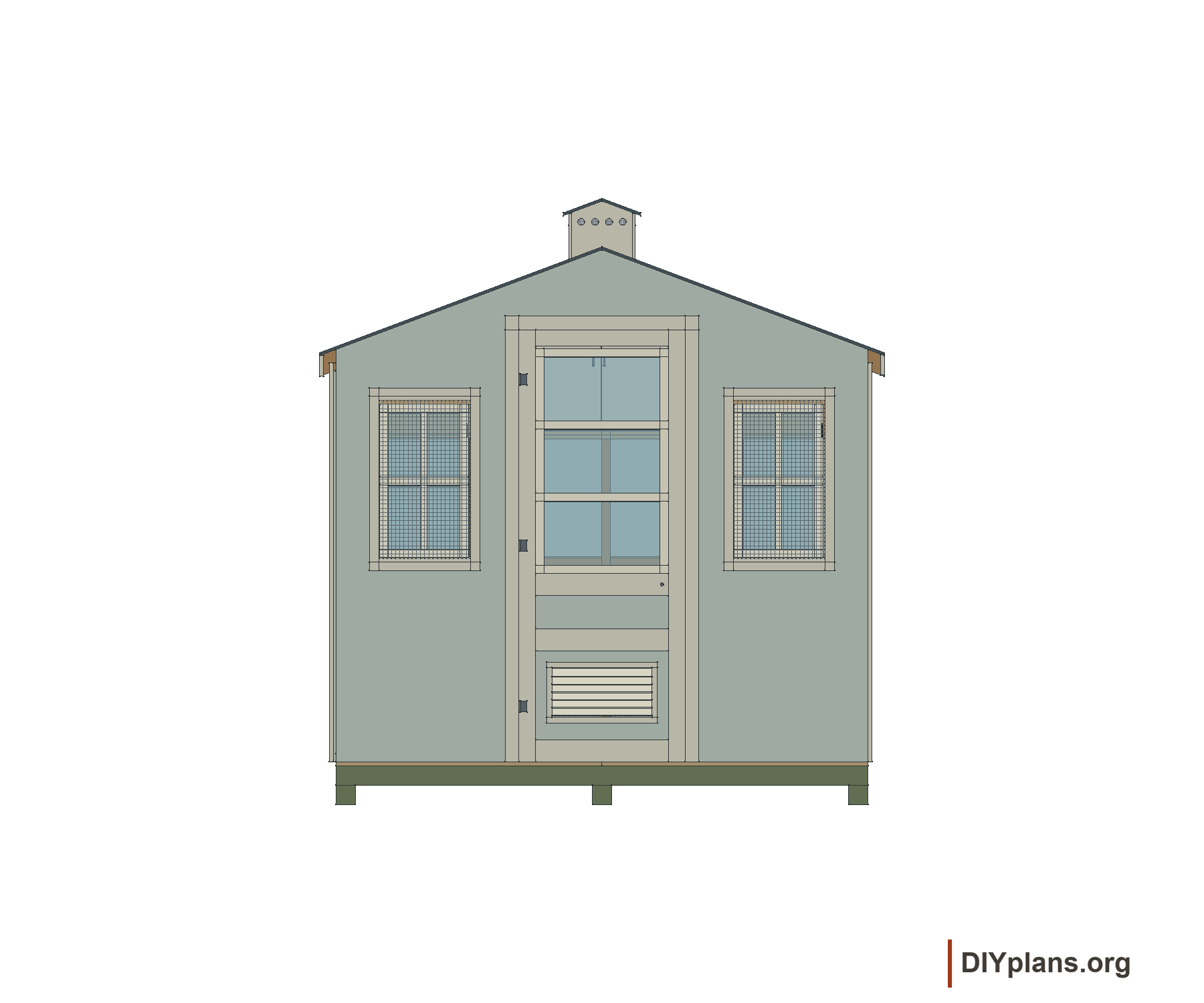
- Place the door in the center of the front gable, with one window on each side. The proposed door opening is 30×78 inches; window openings are 18×30 inches, with sills 36 inches above the finished floor. The door extends into the gable. Confirm the actual openings and header requirements before cutting framing or cladding.
Check: Verify the proposed centered 30 x 78 in door opening and two 18 x 30 in window openings with 36 in sill height; confirm selected units and headers before cutting.
Step 6 Set out the rafters and cupola opening
- The proposed roof uses nominal 2×4 rafters with an 18-inch rise over a 48-inch half-span, a 4½:12 slope. It includes 3-inch overhangs, a split nominal 1×6 ridge and framing around a 12-inch-square roof airway. Timber and plywood extend above the stated roof rise. Rafter seats, ties, bracing and connections need a structural design before rafters are cut.
Check: Check the 18 in rise over the 48 in half-span, 3 in overhangs and 12 in square airway; complete the rafter-seat, tie, bracing and connection details before cutting.
Step 7 Plan panel seams and weather protection
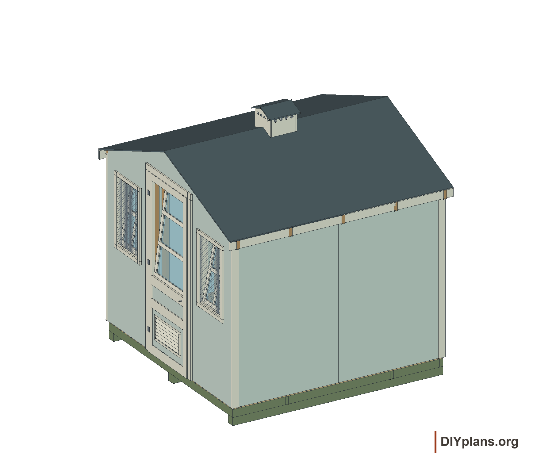
- The proposed wall and roof panels are ½-inch exterior plywood, with corner trim and fascia. Confirm panel thickness for the framing and local loads. Lay out gable and roof panels on available sheets with supported seams and the required gaps. Choose roofing, flashing, seals and finishes, including a watertight connection around the cupola.
Check: Verify supported panel seams and required panel gaps; identify the selected roofing, flashing, seals and finishes, including the cupola connection.
Step 8 Detail the screened cupola and sliding vent
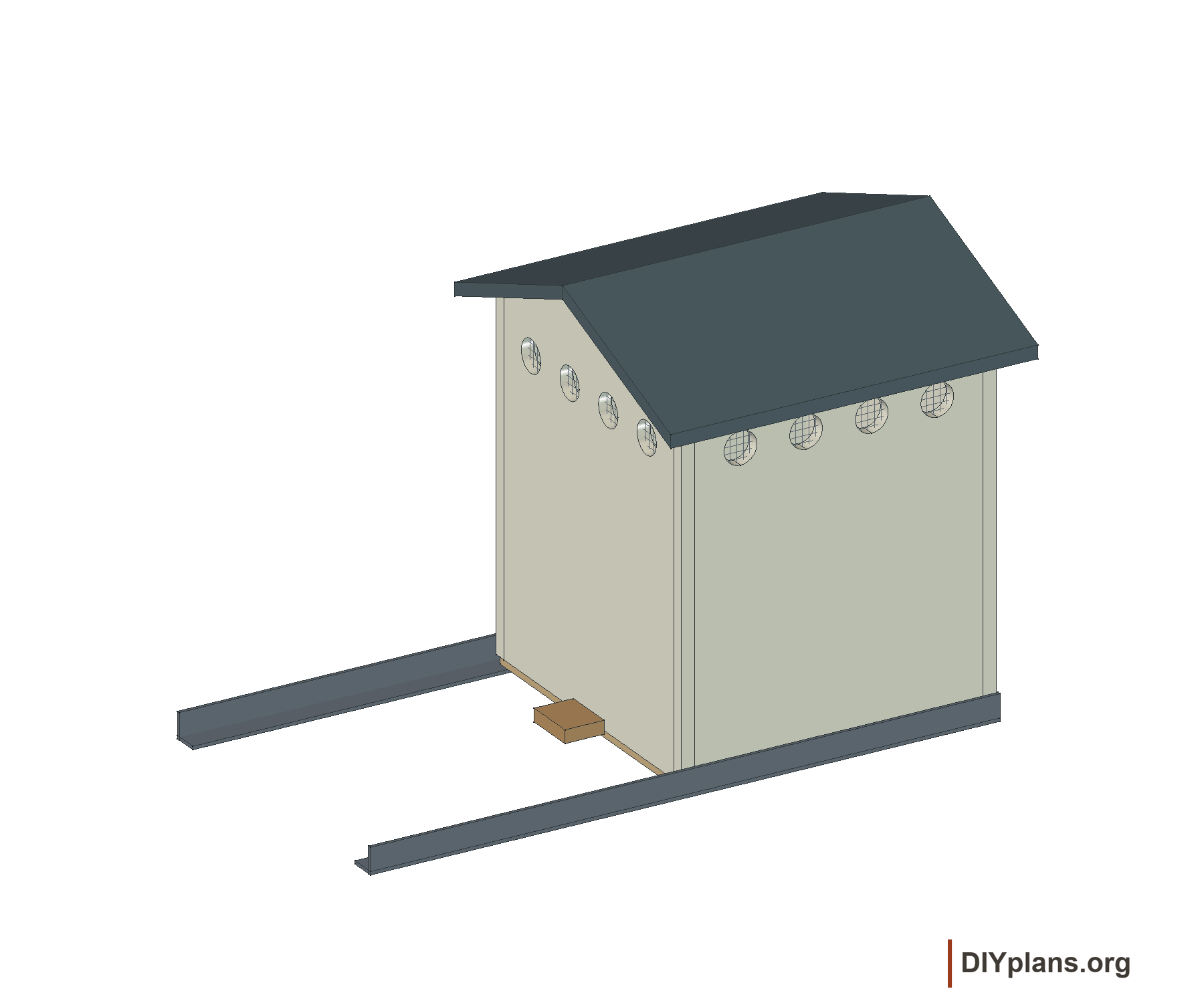
- Provide a 12×12-inch cupola around the roof airway, with four screened 1¼-inch holes on each of its four sides. A plywood throat connects to an adjustable perforated board on angle-iron guides. Proposed dimensions are a 6-inch cupola wall above the ridge, an 11½×12-inch sliding board, two 24-inch guides and 12-inch travel. Finalize the cap, drainage, clearances and attachments before fabrication.
Check: Check the 12 x 12 in cupola, screened 1 1/4 in holes, 11 1/2 x 12 in sliding board and 12 in travel; verify the final cap, drainage and attachment details.
Step 9 Fit the tilt-in sashes and ventilated door
- The front windows and upper door sash tilt inward; the lower door panel has a screened louver. Specify the joinery, weather seals, hinges, stays, latches and glazing. Select screen mesh and hardware for the intended installation, with clearance for the full opening movement.
Check: Check the full sash and door movement against the selected hinges, stays, catches, weather seals and screens; confirm the joinery before fabrication.
Step 10 Build the resting-cell band
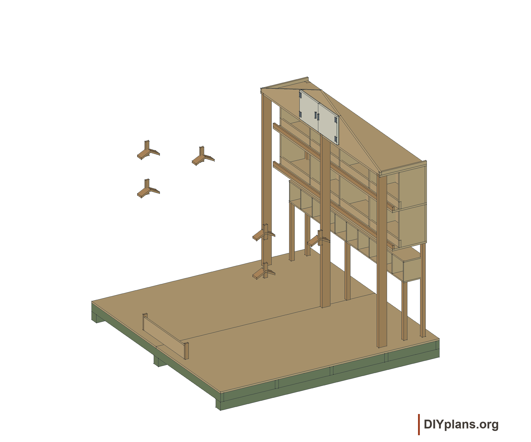
- Place the resting unit between 24 and 33 inches above the floor. Use ½-inch top and bottom boards for 8×8-inch clear cells within the 9-inch-high band. The bottom board underside is at 24 inches and its top at 24½ inches. The proposed unit has ten cells, ½-inch dividers and a 9-inch overall depth; confirm the arrangement for the intended birds.
Check: Check the resting band from 24 to 33 in, ten 8 x 8 in clear cells and 9 in overall depth; verify the selected arrangement and supports.
Step 11 Fit the two nest tiers and landing projections
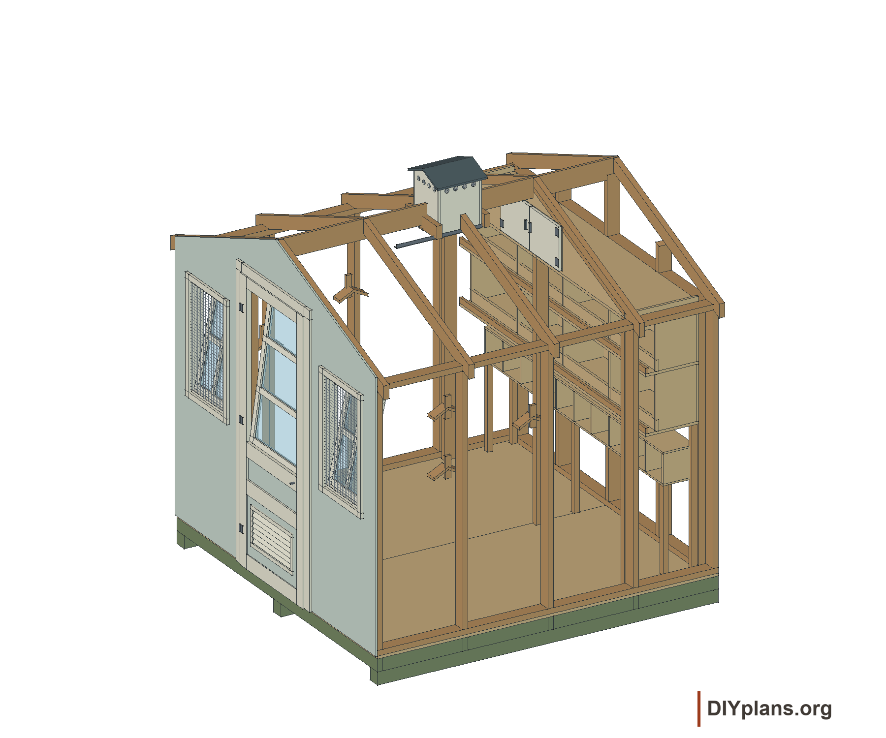
- Leave 7 inches above the resting-cell top, placing the lower nest-floor top at 40 inches. Set the next floor at 56 inches and the storage floor at 72 inches, forming two 16-inch tier bands. Each proposed tier has four nest bays. Allow 12 inches of nest depth and a 3-inch landing projection, for a total shelf depth of 15 inches.
Check: Check floor tops at 40, 56 and 72 in, four nest bays per tier, and the 12 in nest depth plus 3 in landing projection.
Step 12 Install the wall perches, storage and litter board
- The proposed layout has three V-shaped perches on each side wall and paired storage doors above the nests. Confirm perch sizes, projections and attachments. Fit a removable nominal 1×6 litter board at the entrance and check cleaning access, sharp edges and supports before use.
Check: Check three side-wall perches on each side, storage-door access and litter-board removal; confirm perch dimensions and attachments before installation.
Step 13 Check access and construction details
- Check interior measurements, cleaning access and reach to vents and latches. Confirm supports, fasteners and weatherproofing details before construction.
Check: Verify the intended interior dimensions and access to cleaning points, vents and latches; complete supports, fasteners and weatherproofing details before construction.