Before you start
- This is a design concept for viewing and further development, not a construction plan. Do not use these files to order, cut, erect or tension the shelter.
- The roof geometry and reference timber frame are modeled, but their load capacity, connections and foundations have not been established. Areas without heavy snow can still require wind, rain and snow design.
- An accepted membrane/fabricator specification, biaxial properties, installed tension, compensated cutting patterns, qualified seams, clamps and weather seals are required before fabrication.
- Supporting beams extend below the 7 ft 6 in low membrane reference, reducing clear headroom. The CAD envelope is 1 mm thick for display; the reference product sheet states 0.78 mm.
- The roof area and component inventory are geometric quantities. Actual shopping and cutting lists are unavailable.
Dimensions and opening sizes
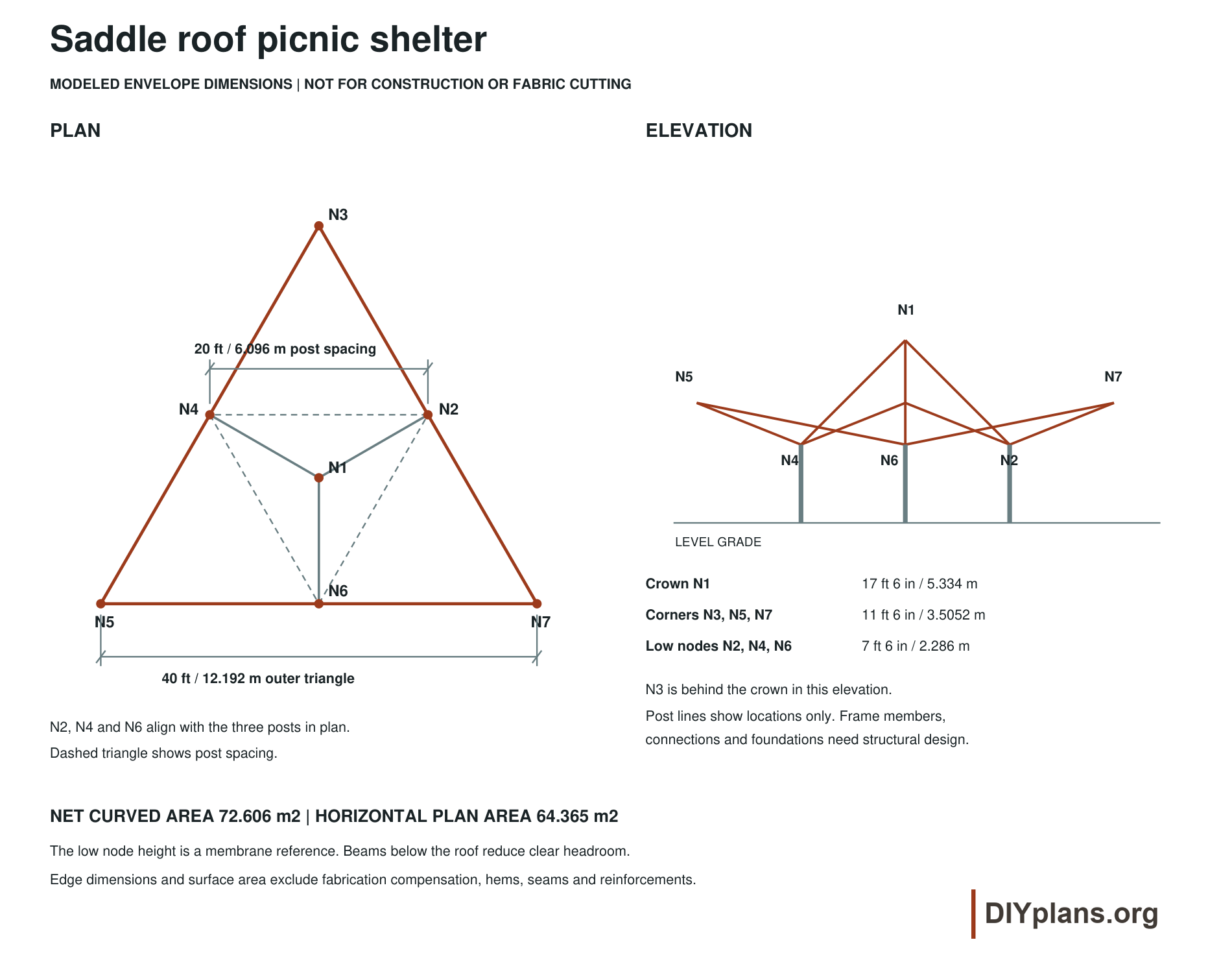
- Outer beam triangle, each sideThe roof ends at this equilateral triangle; no eave extension is included.
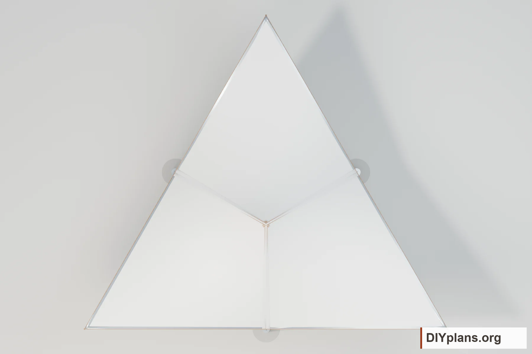
- 40 ft
- Post spacingThree post centers form an equilateral triangle.
- 20 ft
- Lowest roof heightAbove grade. Beams extend below this level, reducing headroom.
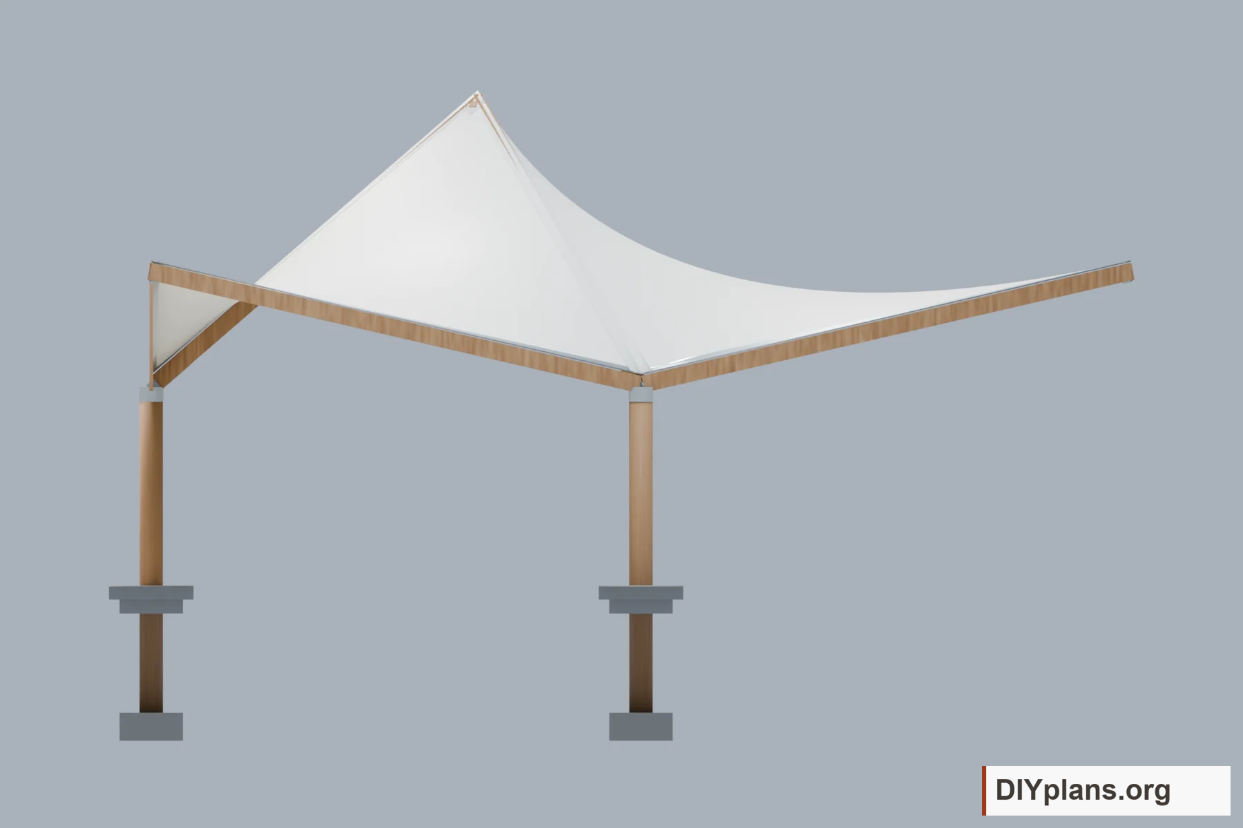
- 7 ft 6 in
- Roof height at outer cornersAbove grade.
- 11 ft 6 in
- Roof height at centerAbove grade.
- 17 ft 6 in
- Curved roof areaExcludes seams, hems, reinforcement, overlaps, fitting allowances and waste. Do not use this as an order quantity.
- 72.606 m²
Shopping list
Real shopping and cutting quantities depend on the engineered membrane, connection system, frame and foundations. The provided inventories contain modeled geometry only.
Tools & equipment
- FreeCAD or a compatible STEP viewer for geometry inspection
- Blender for scene editing and rendering
BEFORE YOU BUILD
Use this work at your own risk
No person or organization makes any guarantee or warranty, express or implied, regarding this design, its documentation, digital files, or website views. They are not professional services and do not create an architect-client or other professional-client relationship. No promise is made about accuracy, completeness, reliability, code compliance, or fitness for your project.
Buildings and building projects are complex, and many things can go wrong. You are responsible for checking dimensions and site conditions, choosing suitable materials and methods, obtaining permits, following codes and manufacturer instructions, and getting qualified professional help when needed. To the fullest extent permitted by law, DIYPlans.org disclaims liability for damages resulting from use of this work. Read the FAQ about your responsibilities.
CC CC BY-NC-SA 4.0 InternationalShare and adapt this free design for noncommercial purposes with appropriate credit. Link to the license, indicate changes, and license adaptations under the same terms.
Instructions
01 Read the triangular layout
- Use the dimensioned plan to locate the three posts and seven envelope nodes. The outer triangle has 40 ft sides and the post triangle has 20 ft sides. These are nominal model dimensions.
Check: Identify the three low attachment nodes and distinguish the outer triangle from post spacing.
02 Compare the roof views
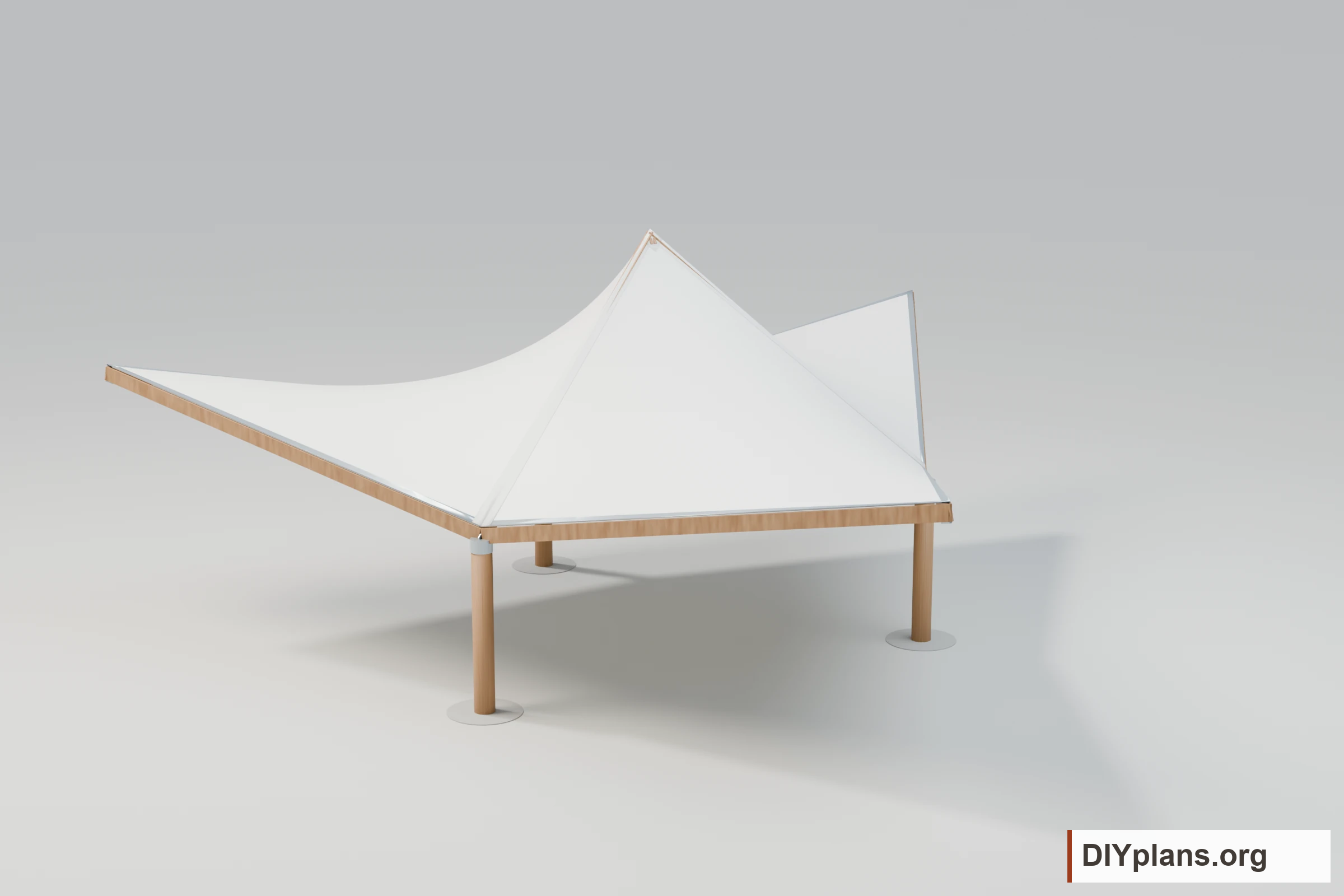
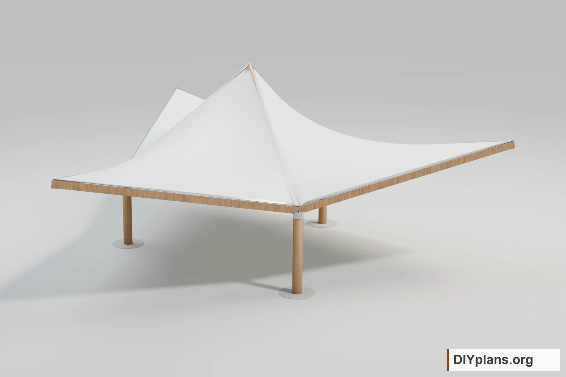
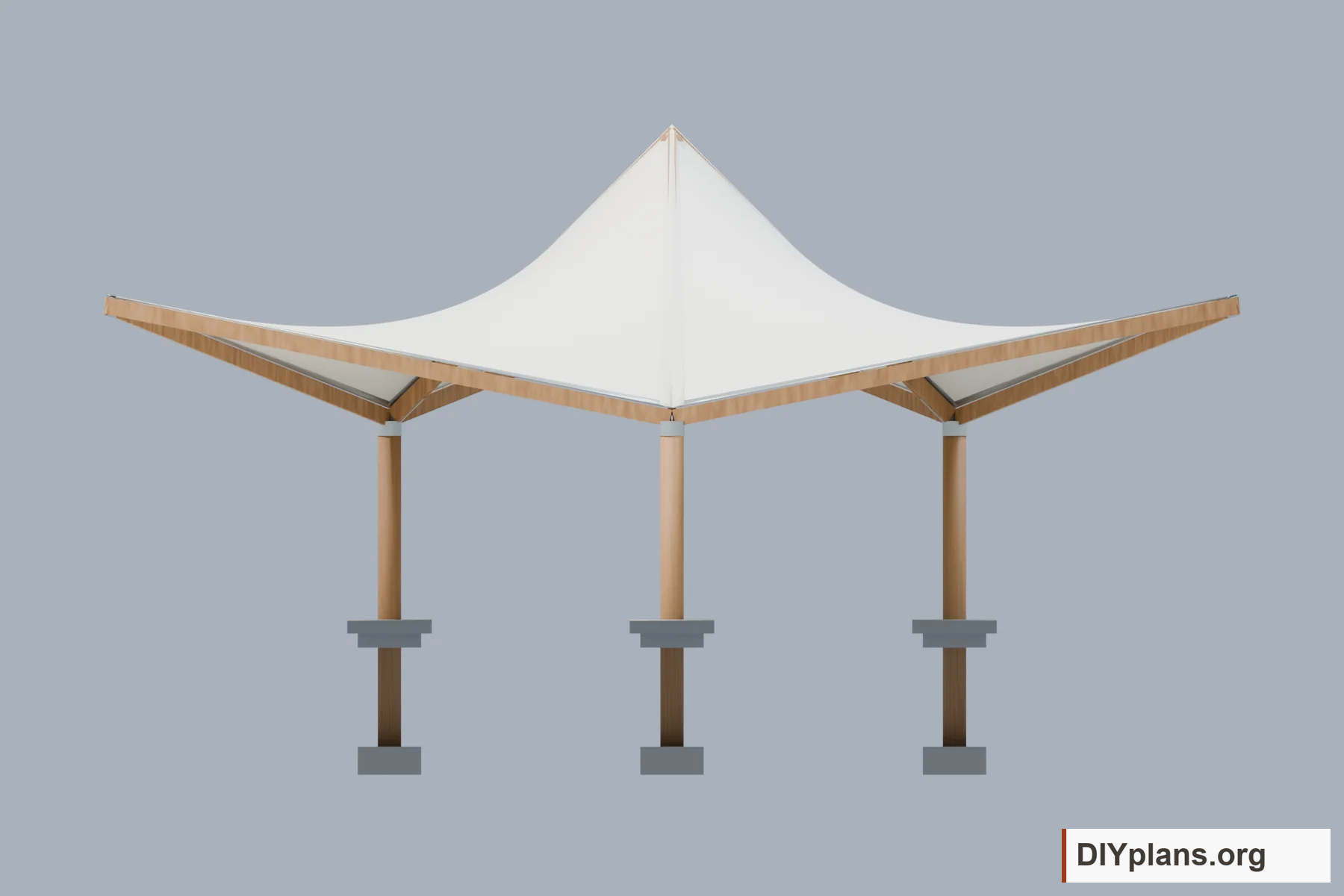
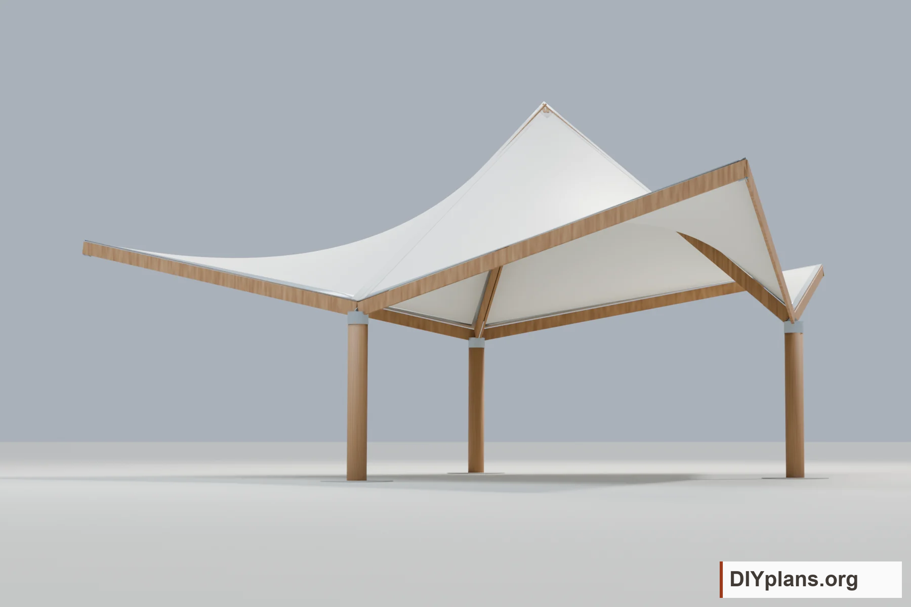
- Compare the overall, reverse and elevation views. Three saddle-shaped membrane assemblies meet at the central crown. The low roof reference is 7 ft 6 in, outer corners are 11 ft 6 in and the crown is 17 ft 6 in above level grade.
Check: Locate the crown, three raised outer corners and three low attachment points in the views.
03 Inspect the exposed frame
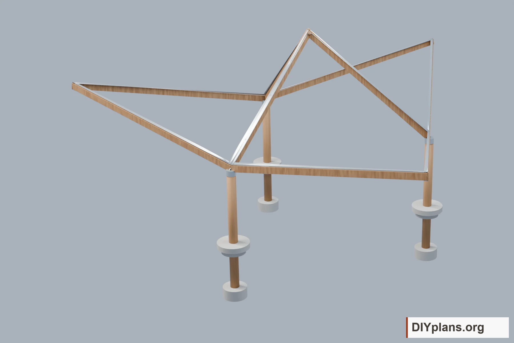
- Use the underside and frame views to see the beams below the fabric and the three foundations. The drawing exposes buried footing regions for explanation. These inherited supports require structural design for membrane loads.
Check: Distinguish the reference frame and footing geometry from an engineered support specification.
04 Understand the proposed attachment
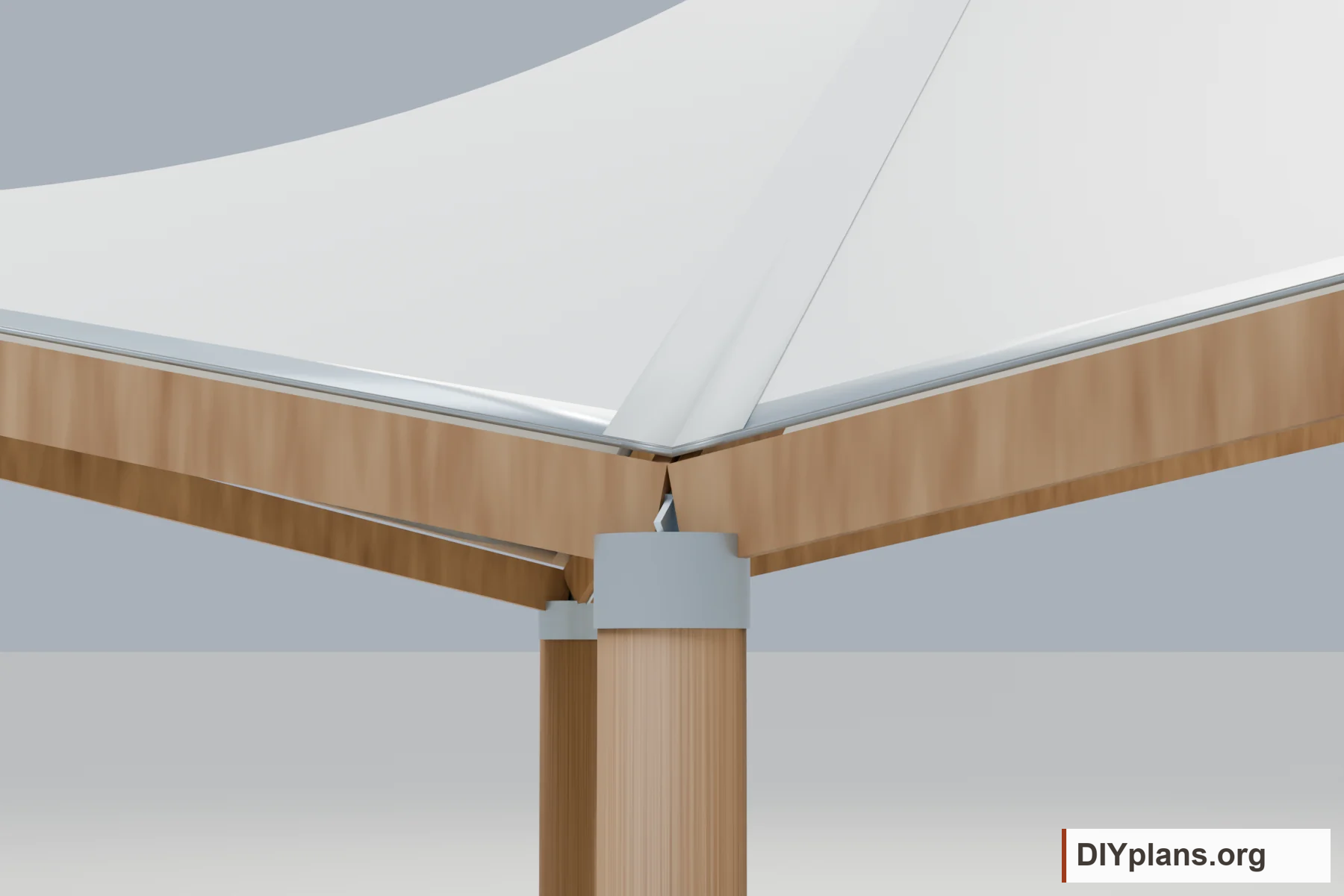
- The connection view shows the intended location of continuous edge clamps and post/beam connections. The bands are schematic zones, not dimensioned rails or tested joints. Crown closures, reinforcement, fasteners and watertight details remain undeveloped.
Check: Recognize which illustrated attachments are placeholders for further design.
05 Use the matching design files
- Open the native CAD for direct geometry inspection, STEP for exchange and Blender for rendering. Stored control points and display thickness do not parametrically regenerate the solids. Read the seven-page guide and geometric inventories together.
Check: Confirm the files are for this three-assembly membrane concept and that inventory rows are not purchase or cutting instructions.
06 Plan the engineering needed to build
- Before construction, obtain accepted fabric data and a numeric site/load envelope, then coordinate membrane form-finding, frame and foundation design, fabric patterns, drainage and installation details. Only the completed coordinated design can supply actual shopping and cutting schedules.
Check: Do not begin fabrication or construction from this concept package; identify the required membrane fabricator and structural design work.