Before you start
- This freestanding table is intended for ordinary domestic seated use. It has not been physically built or load-tested and has no certified load rating.
- Sit along the benches with weight over the seats. Do not stand, jump or climb on the table, sit on the tabletop, or use it as a work platform.
- Use the specified lumber grade and actual sections. Grade or species substitutions, incised stock, different fasteners and changes to the joints require a fresh connection check.
- Use 5/8-in gaps between tabletop boards and 1/2-in gaps between seat boards. Work to the cutting layouts; angled stock-envelope lengths differ from the long-edge lengths.
Dimensions and opening sizes
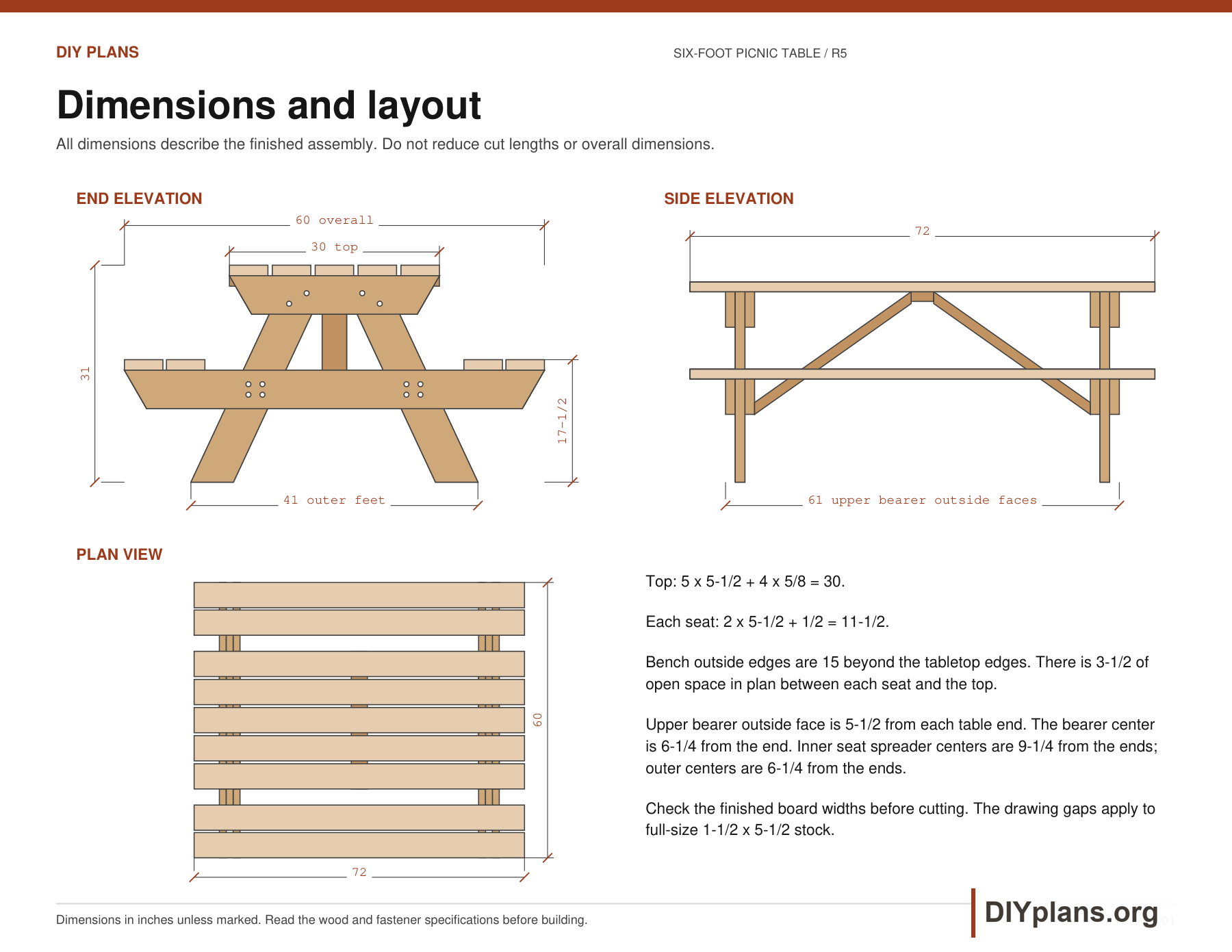
- LengthTabletop and bench slats.
- 72 in
- Overall widthOutside edge to outside edge of the benches.
- 60 in
- Tabletop widthFive 5 1/2-inch boards plus four 5/8-inch gaps.
- 30 in
- Table heightFinished tabletop above ground.
- 31 in
- Seat heightFinished seating surface above ground.
- 17 1/2 in
- Each seat widthTwo 5 1/2-inch boards plus one 1/2-inch gap.
- 11 1/2 in
- Outer foot widthLegs splay 25 degrees from vertical.
- 41 in
- Top slat gapSpacing needed for the 30-inch tabletop.
- 5/8 in
- Seat slat gapOne gap in each bench.
- 1/2 in
- Upper bearer outside-face spacingGives a 5 1/2-inch end overhang. Bearer centers are 59 1/2 inches apart.
- 61 in
Shopping list
| Buy | Material | Stock size |
|---|---|---|
| 15 boards | US Douglas Fir-Larch Select Structural 2x6, unincised | 8 ft; actual 1-1/2 x 5-1/2 in |
| 1 board | US Douglas Fir-Larch Select Structural 2x4, unincised | 10 ft; actual 1-1/2 x 3-1/2 in |
| 8 | ASTM A307 Grade A carbon-steel hex bolts, hot-dip galvanized | 3/8 x 5-1/2 in |
| 16 | ASTM A307 Grade A carbon-steel hex bolts, hot-dip galvanized | 3/8 x 5-1/2 in |
| 48 | Hot-dip galvanized flat washers | 3/8-in bolt size; 1-in outside diameter |
| 24 | Matching hot-dip galvanized 3/8-16 hex nuts | For 3/8-in bolts |
| 62 | ASME B18.6.1 rolled-thread carbon-steel flat-head wood screws, hot-dip galvanized ASTM A153 | #8 x 2-1/2 in; nominal thread diameter 4.1656 mm and root/body diameter 3.3274 mm; head at least 5/16 in |
| 20 | Simpson Strong-Tie 8DHDGPT500 smooth-shank common nails, hot-dip galvanized ASTM A153 Class D | 8d; diameter 3.3274 mm x 2-1/2 in long; full round head |
| 1 can | Rust-Oleum Professional Cold Galvanizing Compound 7585838 | 93% zinc dry-film repair coating |
Quantity notes
Lumber quantities allow 1/8-in saw kerf and trimming, but not rejected boards. Use the specified unincised wood and hot-dip galvanized hardware. Buy spare fasteners.
- US Douglas Fir-Larch Select Structural 2x6, unincised, 8 ft; actual 1-1/2 x 5-1/2 in: Nine boards supply one 72-in slat each. Four boards each supply one 60-in spreader and one 30-in bearer. Two boards each supply two 36-in leg blanks. Allow 1/8-in kerf; buy extra for rejected boards.
- US Douglas Fir-Larch Select Structural 2x4, unincised, 10 ft; actual 1-1/2 x 3-1/2 in: Two 36-in brace blanks and one 30-in center cleat.
- ASTM A307 Grade A carbon-steel hex bolts, hot-dip galvanized, 3/8 x 5-1/2 in: Upper joints clamp two 2x6 bearers around a 2x6 leg, 4-1/2 in total. Use 3/8-16 partially threaded bolts with the smooth shank through the wood and enough usable thread for the 4-1/2-in clamp, two washers and nut. Check the actual hardware before drilling.
- ASTM A307 Grade A carbon-steel hex bolts, hot-dip galvanized, 3/8 x 5-1/2 in: Four bolts in each lower leg joint. Both spreaders and the leg total 4-1/2 in. Use 3/8-16 partially threaded bolts with the smooth shank through the wood and enough usable thread for the 4-1/2-in clamp, two washers and nut. Check the actual hardware before drilling.
- Hot-dip galvanized flat washers, 3/8-in bolt size; 1-in outside diameter: One beneath every bolt head and nut.
- Matching hot-dip galvanized 3/8-16 hex nuts, For 3/8-in bolts: Use galvanized-compatible tapped nuts. Tighten to firm contact without crushing the wood. Recheck after the first moisture cycle; trim or cap sharp thread ends.
- ASME B18.6.1 rolled-thread carbon-steel flat-head wood screws, hot-dip galvanized ASTM A153, #8 x 2-1/2 in; nominal thread diameter 4.1656 mm and root/body diameter 3.3274 mm; head at least 5/16 in: 62 installed: 30 at the tabletop and K1, 32 at seats. Receiving penetration is 1 in including the point. Use the screw layout and 7/64-in pilots. Full threaded portion must reach the receiver. Do not substitute drywall, deck or self-drilling screws by gauge alone. Thread length at least 1-2/3 in; at least 17.0688 mm of full thread enters the receiver beyond the point.
- Simpson Strong-Tie 8DHDGPT500 smooth-shank common nails, hot-dip galvanized ASTM A153 Class D, 8d; diameter 3.3274 mm x 2-1/2 in long; full round head: 20 installed, five at each brace end. Separate paper collation without damaging zinc; hand-drive through the 30-degree pilot jig. Seat the entire head. Cut/file the lower points flush and repair the zinc.
- Rust-Oleum Professional Cold Galvanizing Compound 7585838, 93% zinc dry-film repair coating: Required on filed lower nail ends. Mask the wood and follow label surface preparation, application and drying instructions.
Optional material depending on installation
- Exterior finish selected for the wood species and outdoor exposure. Quantity depends on the product’s coverage and number of coats.
Tools & equipment
- Saw for straight cuts, 25-degree leg miters, 30-degree crosspiece miters and 35.288-degree brace bevels.
- Drill/driver, 13/32-in bolt bit, 7/64-in screw pilot bit, 82-degree countersink, 3/32-in nail pilot bit, and a fixed guide at 30 degrees to the broad brace face.
- Clamps, temporary frame supports, a helper, tape measure, square, angle gauge, pencil and a lumber moisture meter.
- Two wrenches, hammer, sanding tools, eye and hearing protection; a cutter or grinder and zinc-rich repair coating for exposed nail points.
BEFORE YOU BUILD
Use this work at your own risk
No person or organization makes any guarantee or warranty, express or implied, regarding this design, its documentation, digital files, or website views. They are not professional services and do not create an architect-client or other professional-client relationship. No promise is made about accuracy, completeness, reliability, code compliance, or fitness for your project.
Buildings and building projects are complex, and many things can go wrong. You are responsible for checking dimensions and site conditions, choosing suitable materials and methods, obtaining permits, following codes and manufacturer instructions, and getting qualified professional help when needed. To the fullest extent permitted by law, DIYPlans.org disclaims liability for damages resulting from use of this work. Read the FAQ about your responsibilities.
CC CC BY-NC-SA 4.0 InternationalShare and adapt this free design for noncommercial purposes with appropriate credit. Link to the license, indicate changes, and license adaptations under the same terms.
Instructions
01 Choose and measure the lumber
- Use grade-stamped US Douglas Fir-Larch Select Structural 2x6 and 2x4, without incising. Actual sections must be 1-1/2 x 5-1/2 in and 1-1/2 x 3-1/2 in. Check moisture at 19% or less before assembly. Select straight boards without splits or loose knots at joints. Measure stock before cutting; do not reduce the cut lengths or finished table dimensions. The purchase allocation allows 1/8-in saw kerf and trimming, but not rejected boards.
Check: All structural 2x stock has the specified species and grade stamp, matches the stated finished section, and has no split at a planned joint. Moisture is checked before assembly.
02 Cut the slats, bearers and cleats
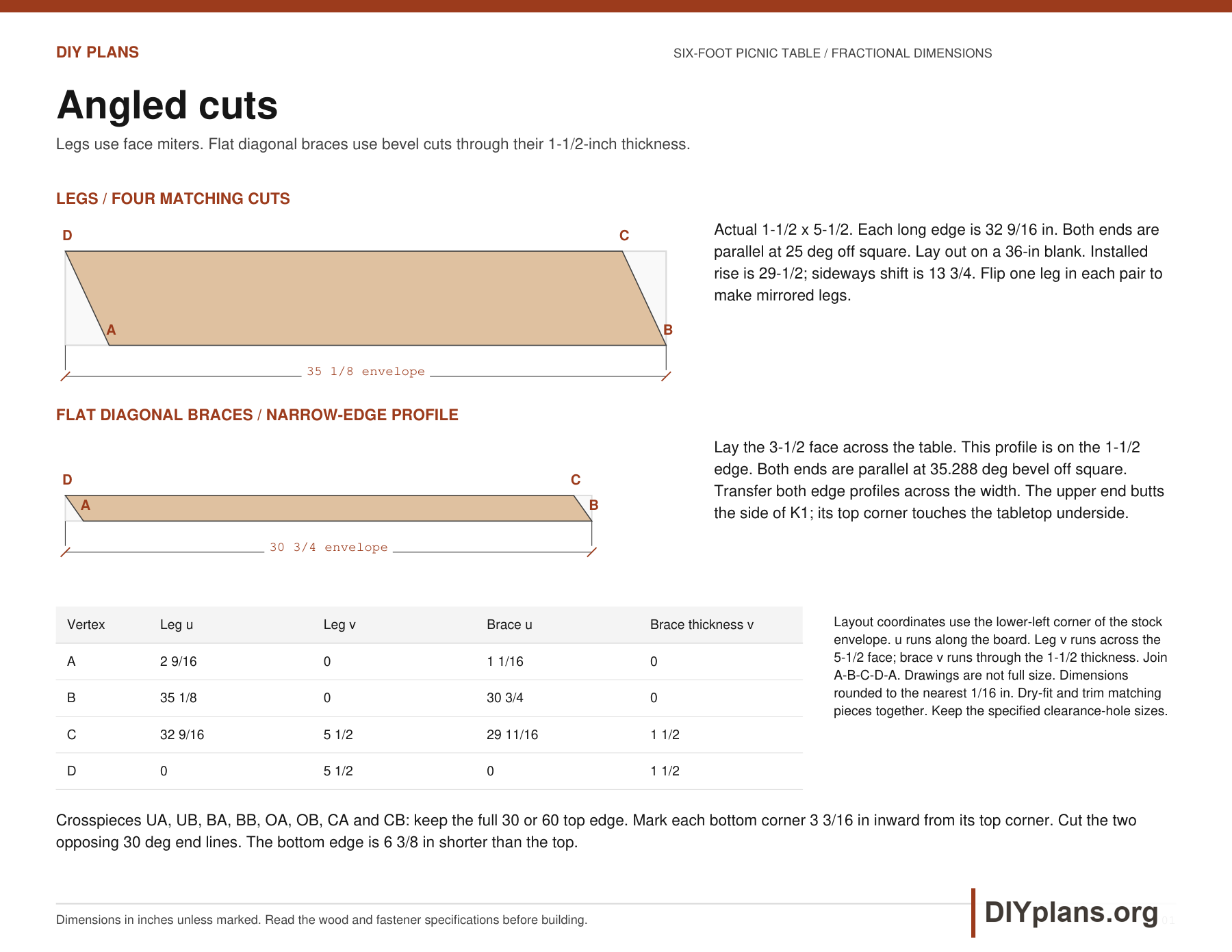
- Cut five 2x6 tabletop slats and four 2x6 seat slats to 72 in with square ends. Cut four 2x6 upper bearers to 30 in along their full top edges and four 2x6 seat spreaders to 60 in along their full top edges. On these eight crosspieces, mark each bottom corner 3 3/16 in inward and cut opposing 30-degree end miters. Cut the 2x4 center cleat K1 to 30 in with square ends. Keep the blade square to the board face for these cuts.
Check: Count and label every cut part against the cut list. Slat ends are square, paired crosspieces match, and the retained full top edges measure 30 or 60 inches as listed.
03 Cut four matching legs
- Start with four 36-inch 2 x 6 blanks. Each finished leg has two parallel 25-degree miters and measures 32 9/16 inches along either long edge. The square-ended stock envelope is 35 1/8 inches, so do not confuse it with the long-edge length. Use the A-B-C-D coordinates in the cut-layout drawing on this page, mark to the nearest 1/32 inch and dry-fit. Flip one leg in each pair to make mirrored legs. Installed leg rise is 29-1/2 inches and sideways shift is 13 3/4 inches.
Check: All four long edges measure 32 9/16 inches and the parallel 25-degree miters match. Each end frame has one mirrored pair.
04 Lay out the two end frames
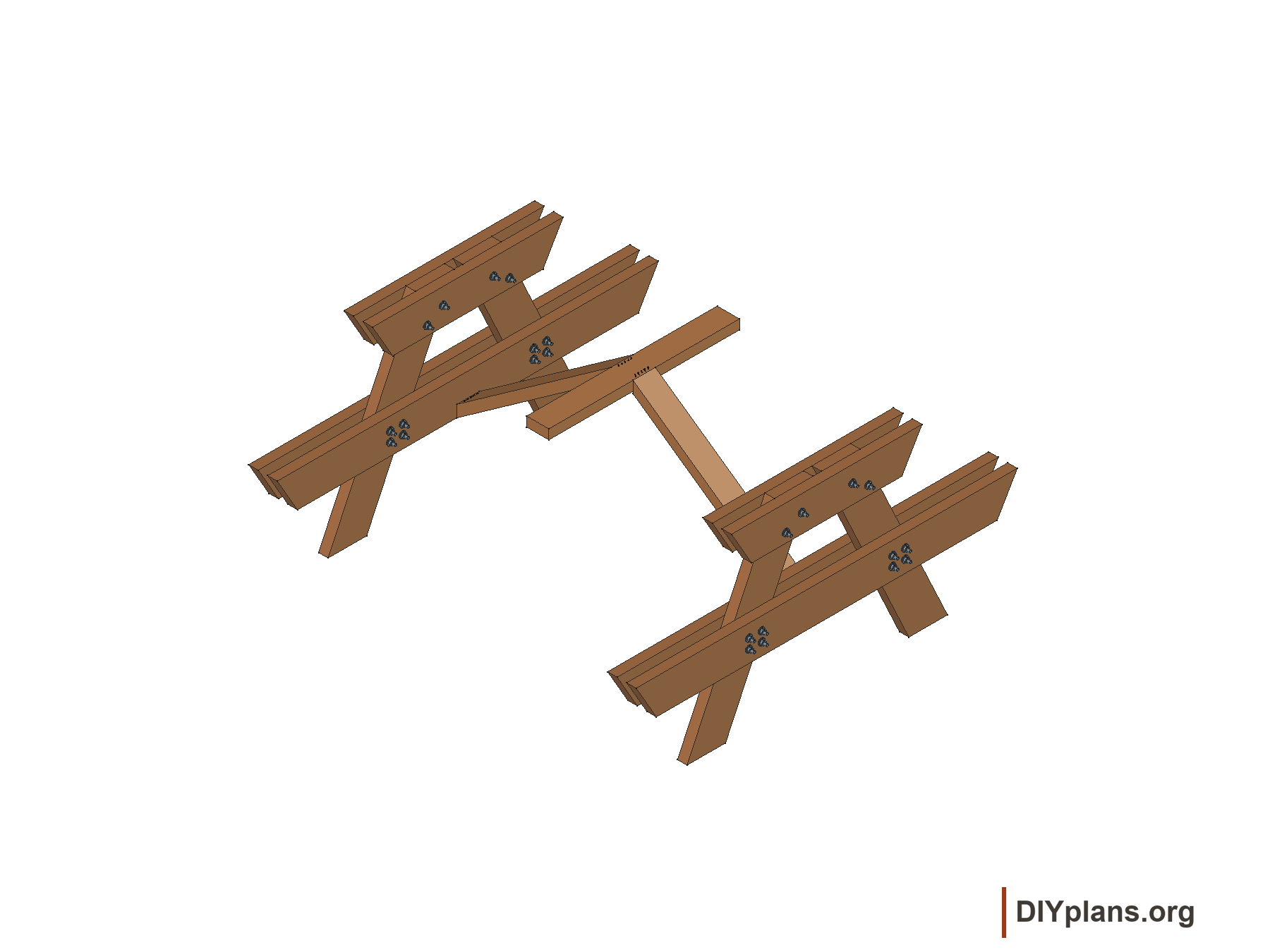
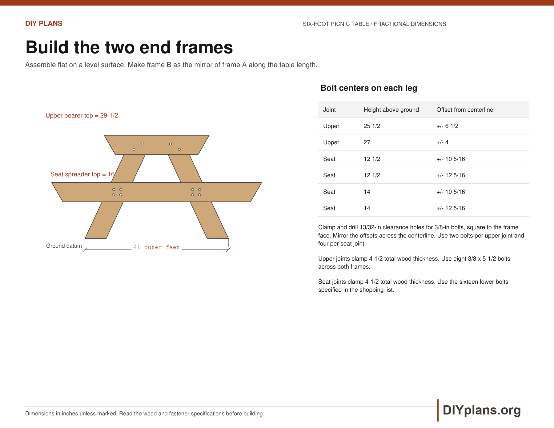
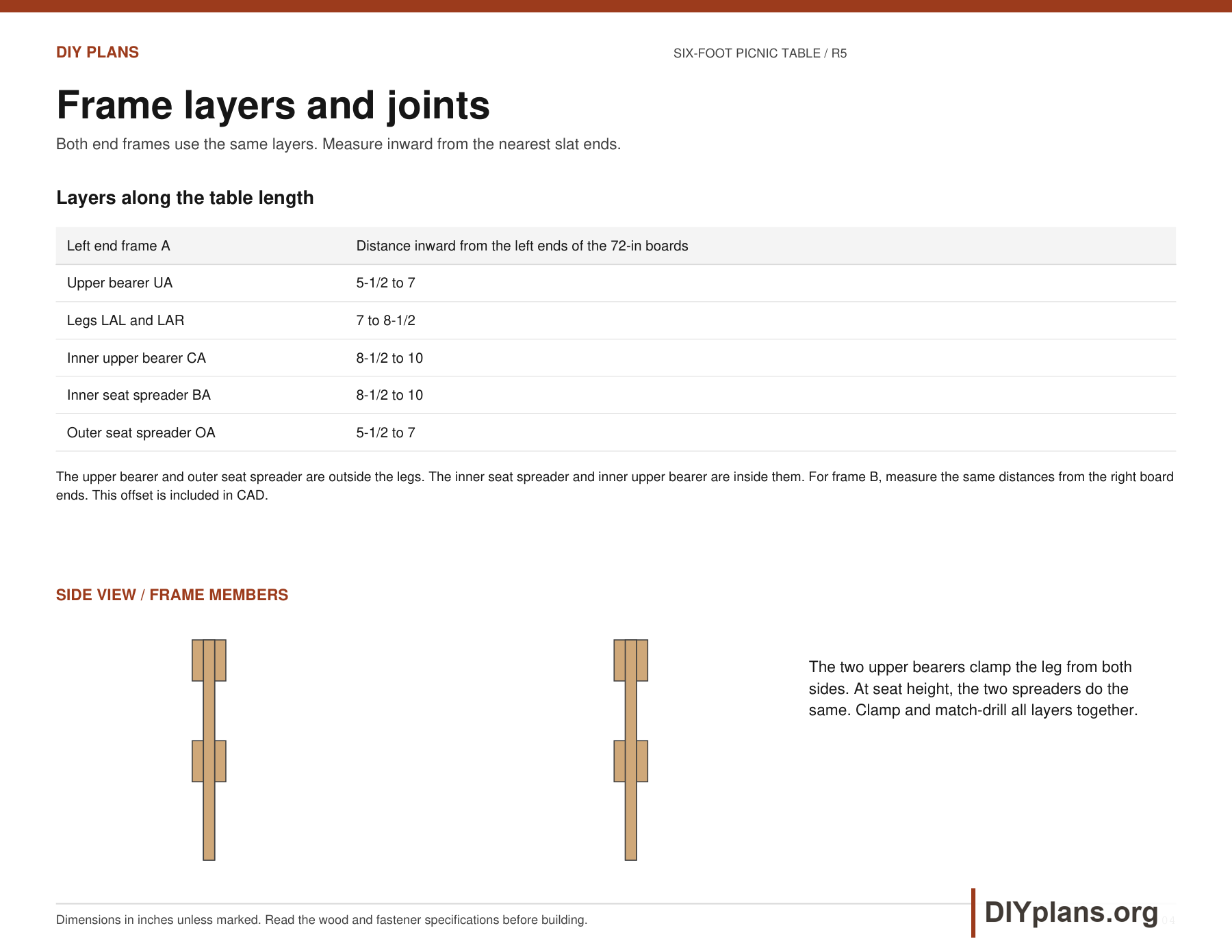
- Assemble each end frame flat on a level surface. Set the outside feet 41 in apart. Set all upper bearer top edges 29-1/2 in above the ground datum and all seat spreader tops 16 in above it. Every leg is sandwiched between two 2x6 upper bearers and between two 2x6 seat spreaders. Every bolted joint clamps 4-1/2 in of wood. Follow the frame-layer drawing.
Check: Both frames match the layer drawing, with 41 inches across the outside feet, upper bearing edges at 29-1/2 inches, and seat bearing edges at 16 inches.
05 Clamp, drill and bolt the frames
- Clamp all three wood layers together before drilling 13/32-in clearance holes square to the end-frame face. On each positive-side leg, the upper centers are 25-1/2 in above ground at 6 1/2 in from the table centerline, and 27 in high at 4 in from center. Mirror these across the centerline for the opposite leg.
- Each lower joint uses a rectangular four-hole grid, 2 in wide by 1-1/2 in high. Its bottom row is 12-1/2 in above ground and its top row is 14 in. The two columns are 10 5/16 and 12 5/16 in from the centerline. Mirror the grid for the opposite leg. Make both end frames match. Use the numerical dimensions; the printed image is not a full-size template.
- Install 24 specified 3/8 x 5-1/2-in bolts: two in each upper joint and four in each lower joint. Put one washer under every head and nut. Match-drill; do not pull misaligned holes together with bolts. The wood clamp is 4-1/2 in at every joint.
Check: Every matched bolt passes without forcing. Washers bear flat, the nut reaches firm contact, and at least two full threads project without leaving a sharp snag.
06 Support the frames and attach the tabletop
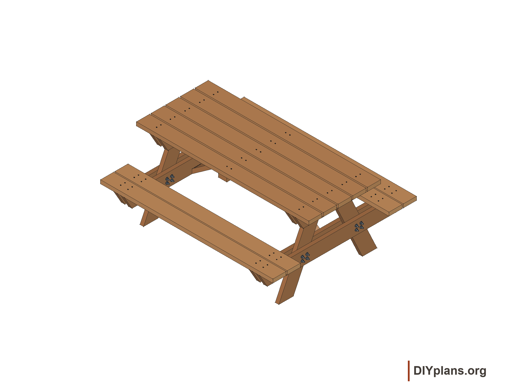
- With a helper, stand the frames upright and clamp them to temporary supports. Lay five top slats face up with 5/8-in spacers and aligned ends. Set each outside upper bearer face 5-1/2 in inward from its nearest slat end. Clamp K1 flat beneath the tabletop, centered at the 36-in midpoint.
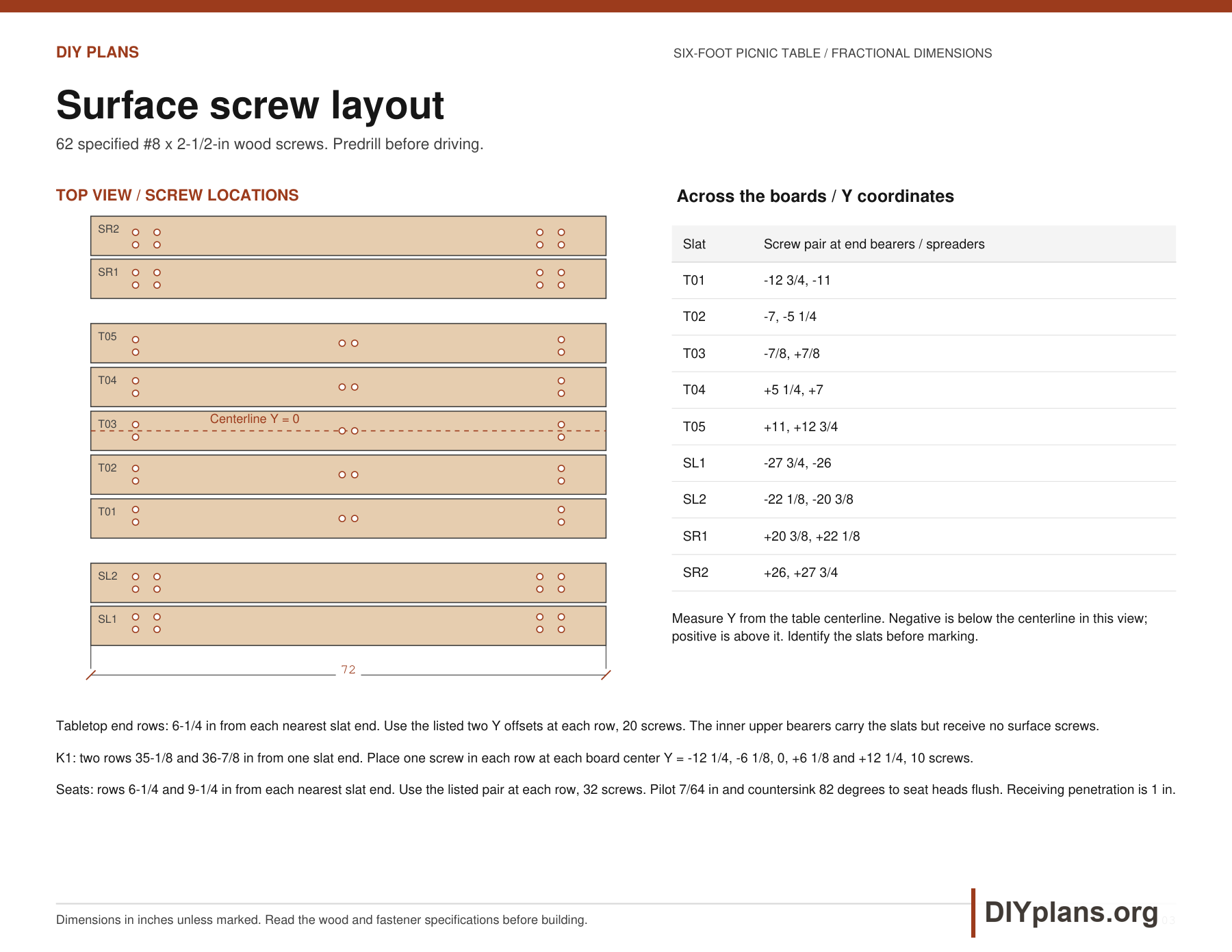
- Use the surface-screw drawing to mark two screws per slat at each outer upper bearer and two per slat into K1, 30 screws total. Outer bearer screw rows are 6-1/4 in from the slat ends. Predrill 7/64-in pilots, maintain 1-in penetration into the receiving wood, and use an 82-degree countersink only deep enough for a flush head. For an unthreaded shank different from 3.3274 mm, bore its portion about 7/8 of the measured shank diameter.
Check: The top is 30 inches wide, all four gaps are 5/8 inch, ends align, and K 1 is flat and centered at the 36-inch midpoint.
07 Install the seats and square the table
- Keep both frames supported. Install two 72-in seat slats on each side with 1/2-in spacers and ends aligned with the tabletop. Set outside edges 60 in apart. Each seat is 11-1/2 in wide and 17-1/2 in high.
- Fasten every seat slat at both inner and outer spreaders at both ends, with two screws at each crossing, 32 screws total. Rows are 6-1/4 and 9-1/4 in from the nearest slat end. Follow the surface-screw offsets across each slat and the same pilot/countersink specification as the top. Check equal diagonals and all feet on the level surface before tightening.
Check: Both 11-1/2-inch seats have 1/2-inch gaps, their outside edges are 60 inches apart, and all feet contact the level work surface.
08 Fit both diagonal braces
- Lay both diagonal 2 x 4 braces flat, with their 3-1/2-inch width across the table and 1-1/2-inch thickness normal to their broad faces. Their upper ends butt opposite sides of the flat center cleat K1, 1-3/4 inches from the table midpoint; the top corners touch the tabletop underside at 29-1/2 inches. The lower ends meet the inside spreader faces, 26 inches from the midpoint. Both ends are parallel 35.288-degree bevels off square, cut through the 1-1/2-inch thickness. Use 36-inch blanks; the finished stock envelope is 30 3/4 inches. Use the narrow-edge coordinate profile and transfer it across the width. With actual modern stock, each upper end extends 5/16 inch below K1 while bearing across its full 1-1/2-inch side height. Dry-fit without forcing.
Check: Both braces bear firmly against their receivers without forcing the frame out of square. Their 3-1/2-inch faces remain flat and the upper top corners meet the tabletop underside.
09 Fasten the fitted braces
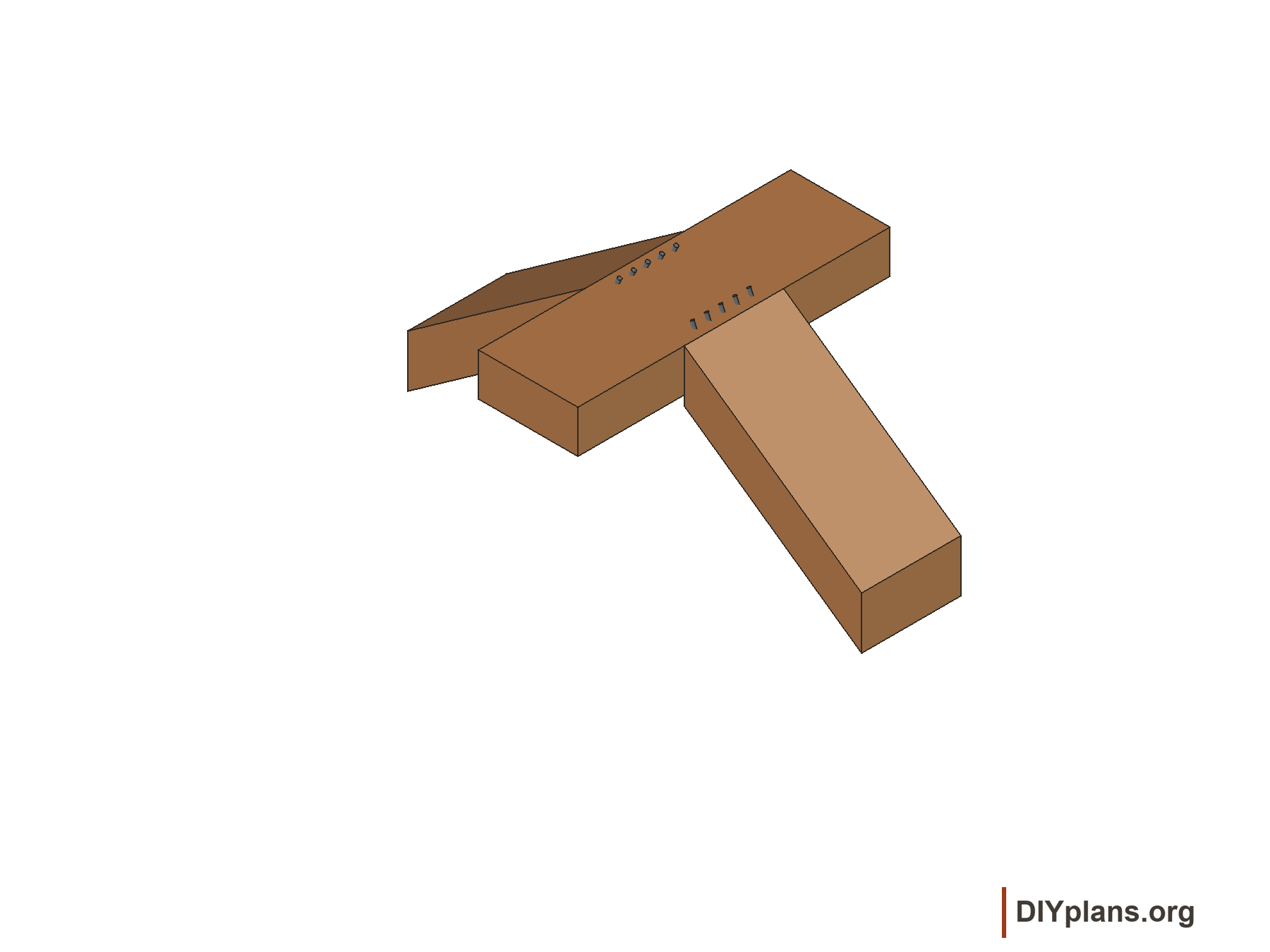
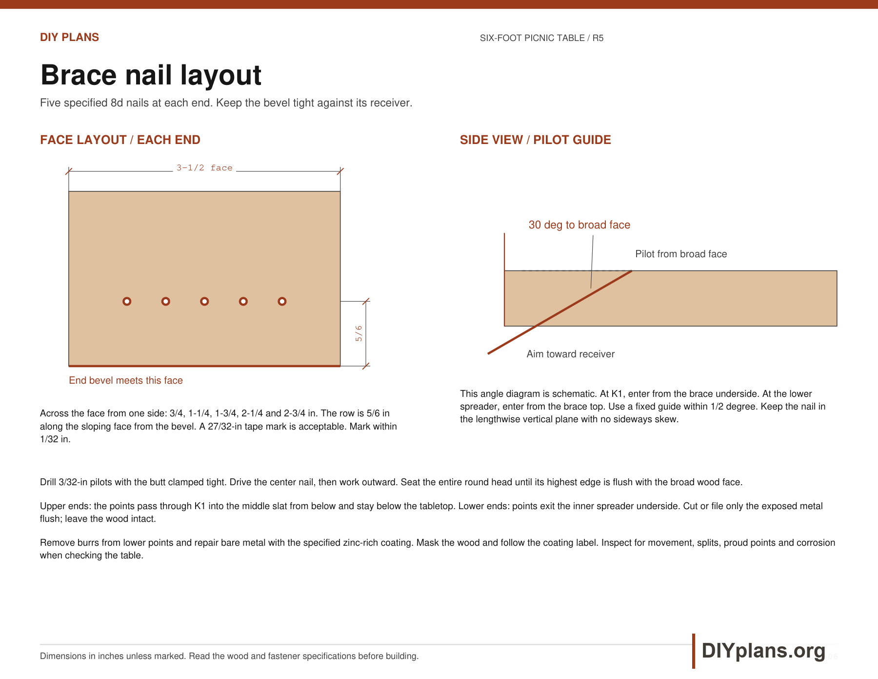
- Use five specified 8d nails at each end, 20 total. Mark across each 3-1/2-in face at 3/4, 1-1/4, 1-3/4, 2-1/4 and 2-3/4 in from one side. Mark the row 5/6 in along the broad face from the end bevel; a 27/32-in tape mark is acceptable. Work within 1/32 in.
- At the upper ends, drill from the underside of each brace toward K1. At the lower ends, drill from the top face toward the inner spreader. Use a fixed 30-degree guide, within 1/2 degree, and a 3/32-in pilot bit. Aim in the lengthwise vertical plane with no sideways skew. Clamp the butt tight, then drill and drive the middle nail before working outward.
- Seat the entire round head with its highest edge flush to the brace face. Upper points enter the middle tabletop slat from below and must remain below the eating surface. Lower points exit the inner spreader underside. Cut, file or grind only the exposed metal flush with that underside, remove burrs, and coat the bare ends with the specified zinc-rich repair product. Protect the wood and follow the coating label.
Check: All four joints are tight and each has five nails at the shown face, spacing and angle. Heads are fully seated. No upper point exits the tabletop. Lower points are flush, smooth and coated.
10 Finish and inspect the table
- Ease sharp edges and sand the seats and tabletop smooth. Tighten nuts to firm contact without crushing the wood. Trim or cap sharp bolt ends. Remove temporary supports after all joints are secure. Check for rocking, racking, splits, soft wood and loose fasteners before use, after the first outdoor moisture cycle, and periodically thereafter. Stop using the table until damaged parts or loose joints are repaired.
- Coat all faces and cut ends with an exterior finish suitable for Douglas Fir. Keep the feet out of soil and standing water, use a firm level surface, and let the wood dry between wetting. Maintain the finish and store under cover when practical.
Check: No sharp edges, proud fastener points, splits, loose joints, rocking or visible racking remain. Recheck the hardware after the first outdoor moisture cycle and periodically afterward.