Play movementStop movement
Before you start
- This compact build follows the 5 1/2 in cutting layout. The source sheet also lists 1 x 8 stock and six-inch perches; those conflict with the drawn chamber. Use the stock and short perch dimensions in this package together.
- Keep the high 2 in entrance shown in the source. Hole positions, door clearances, exact bevels and fastening locations here are explicit construction choices added to make the package consistent.
- Use untreated wood, leave the inside rough, and do not add an exterior perch. Clamp small parts, wear eye protection and control wood dust. Drill on a backing board.
- The model verifies geometry and door movement. No physical build, bird-occupancy test or species-specific suitability test has been performed.
Dimensions and opening sizes
- Outside widthActual board width.
- 5 1/2 in
- Backboard heightExtends 2 below the floor underside.
- 17 in
- Body depthIncludes front and back thickness.
- 7 in
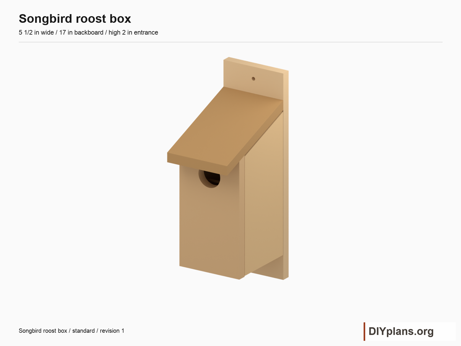
- Depth including roofAbout 8 3/4; finished roof underside is 8 1/2 along its slope; cut from a 9 in blank.
- 8 3/4 in
- Entrance diameterHigh entrance, center 8 above front bottom.
- 2 in
Shopping list
| Buy | Material | Stock size |
|---|---|---|
| 1 | Untreated cedar board | Nominal 1 x 6 x 8 ft; actual 3/4 x 5 1/2 in |
| 1 length | Untreated hardwood dowel | 1/4 in diameter x 36 in |
| 1 box of at least 25 | Exterior wood screws | #6 x 1 1/4 in; stainless or corrosion-resistant |
| 1 set | Galvanized smooth wire and small galvanized nails | 12 in wire, about 18 gauge; two 3/4 in nails |
| 1 bottle | Exterior wood glue | Small bottle |
| 1 set | Exterior mounting screws with flat washers | Two #10 x 2 1/2 in screws; two washers sized for #10 |
Quantity notes
One box from one 96 in board, with six separate blanks and 1/8 in kerf allowance. Hardware includes a wood-post mounting option.
- Untreated cedar board, Nominal 1 x 6 x 8 ft; actual 3/4 x 5 1/2 in: Select straight, sound stock. Six blanks total 65 1/2 in; allow 1/8 in saw kerfs and end trimming. Keep inside faces rough.
- Untreated hardwood dowel, 1/4 in diameter x 36 in: Cut six 4 1/4 in perches. Their total length is 25 1/2 in before kerfs.
- Exterior wood screws, #6 x 1 1/4 in; stainless or corrosion-resistant: Use 18 screws: 16 fixed assembly screws and 2 side pivots. Leave pivot heads just loose enough to turn.
- Galvanized smooth wire and small galvanized nails, 12 in wire, about 18 gauge; two 3/4 in nails: Loop wire around the two latch nails. Fold cut ends flat outside; leave no snagging loop inside.
- Exterior wood glue, Small bottle: Glue only the dowels into blind sockets. Remove squeeze-out and allow full cure.
- Exterior mounting screws with flat washers, Two #10 x 2 1/2 in screws; two washers sized for #10: For a sound existing wood post: at least 1 1/2 in penetration after the 3/4 in back and washers. Confirm the post supports the box and use matching pilot holes.
Required installation supplies
- Provide a sound existing wood post with safe access, or select support-specific mounting hardware before installation.
Optional material depending on installation
- A freestanding post, footing and predator baffle are site-dependent and are not included in the board or hardware quantities.
Tools & equipment
- Tape measure, square and pencil
- Saw with controlled bevel adjustment and clamps
- Drill/driver, 2 in hole saw, 1/4 and 5/16 bits, screw pilots and clearance bits
- Depth stop, countersink, sanding block and coarse sandpaper
- Eye protection and dust protection
BEFORE YOU BUILD
Use this work at your own risk
No person or organization makes any guarantee or warranty, express or implied, regarding this design, its documentation, digital files, or website views. They are not professional services and do not create an architect-client or other professional-client relationship. No promise is made about accuracy, completeness, reliability, code compliance, or fitness for your project.
Buildings and building projects are complex, and many things can go wrong. You are responsible for checking dimensions and site conditions, choosing suitable materials and methods, obtaining permits, following codes and manufacturer instructions, and getting qualified professional help when needed. To the fullest extent permitted by law, DIYPlans.org disclaims liability for damages resulting from use of this work. Read the FAQ about your responsibilities.
CC CC BY-NC-SA 4.0 InternationalShare and adapt this free design for noncommercial purposes with appropriate credit. Link to the license, indicate changes, and license adaptations under the same terms.
Instructions
01 Measure the stock and mark the pieces
- Use untreated cedar measuring 3/4 thick and 5 1/2 wide. Measure it before marking. Rip wider stock to 5 1/2; different thickness requires changing the floor width and fastener layout.
- Mark the six board blanks in the cut list. Their lengths total 65 1/2 in. Leave the saw kerf on the waste side of every line; a 96 in board provides over 28 in spare after seven 1/8 in kerfs and 1 in end trim.
- Label the inside face and front edge of each side. The two side blanks are the same handed slope once installed. Keep rough faces toward the chamber.
Check: Stock is 3/4 x 5 1/2 and every blank fits without using a knot or split at a screw or perch hole.
02 Cut the panels and roof bevels
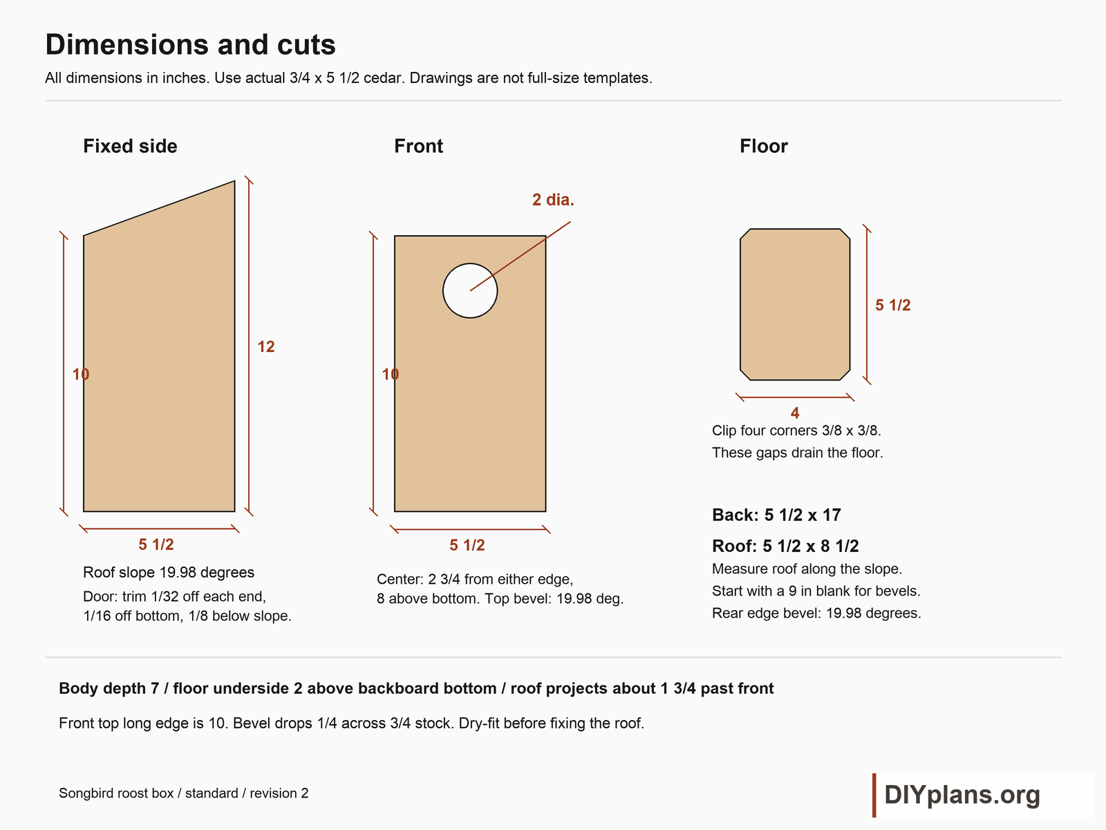
- Cut the back 17 long and the front 10 at its long top edge. Cut two side blanks 12 long. On each side, mark 10 at the front edge and 12 at the rear, then join the marks and cut the slope.
- The slope is 2 rise over 5 1/2 run, or 19.98 degrees. Bevel the front top to match: it drops 1/4 in across the 3/4 thickness toward the outside face. Test the fit with a side before fastening.
- Start the roof with a 9 in blank to allow for both bevel cuts; finish it 8 1/2 along its underside. Bevel its rear edge 19.98 degrees so it meets the vertical back. The roof underside bears on the fixed side and front; the front overhang is about 1 3/4.
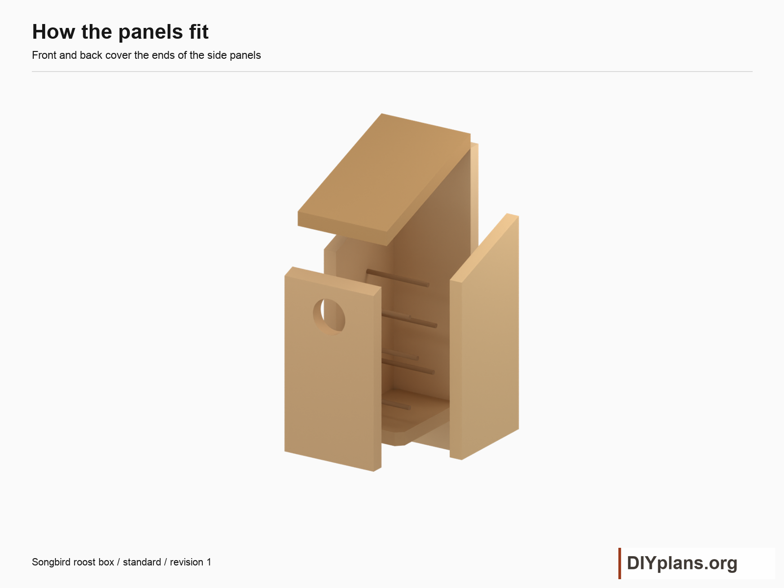
- Cut the floor 4 wide by 5 1/2 deep. Clip each corner 3/8 in both directions. The 4 in dimension fits between the sides; the 5 1/2 dimension runs front to back.
Check: Dry-fitted front, fixed side and roof meet without forcing the slope, and the floor fits between the sides.
03 Drill the entrance, perch sockets and mounting holes
- Clamp the front to a sacrificial backing board. Bore a 2 in entrance centered 2 3/4 from either edge and 8 above the bottom. Ease splinters without polishing the rough inside face. Do not add an outside perch.
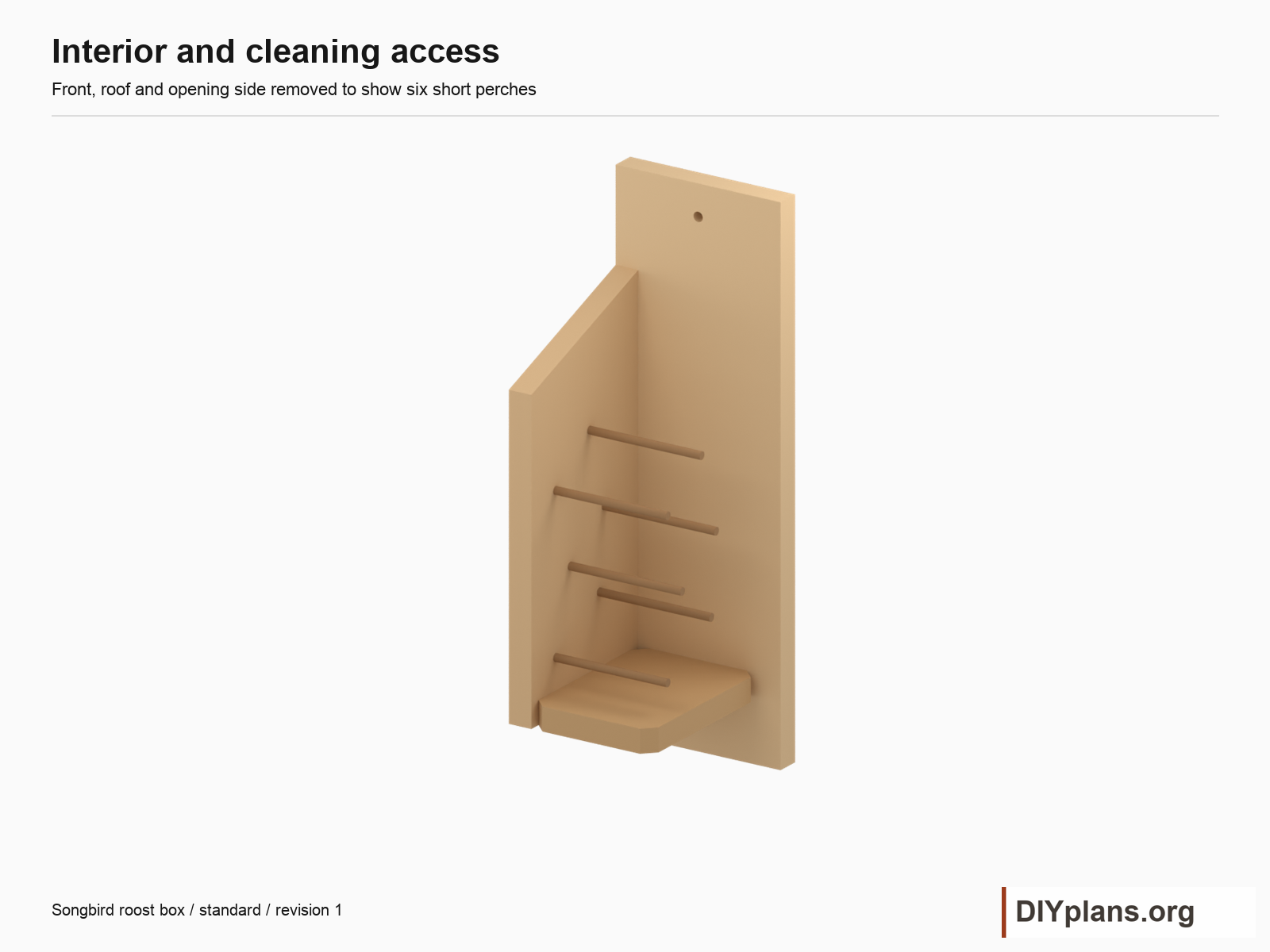
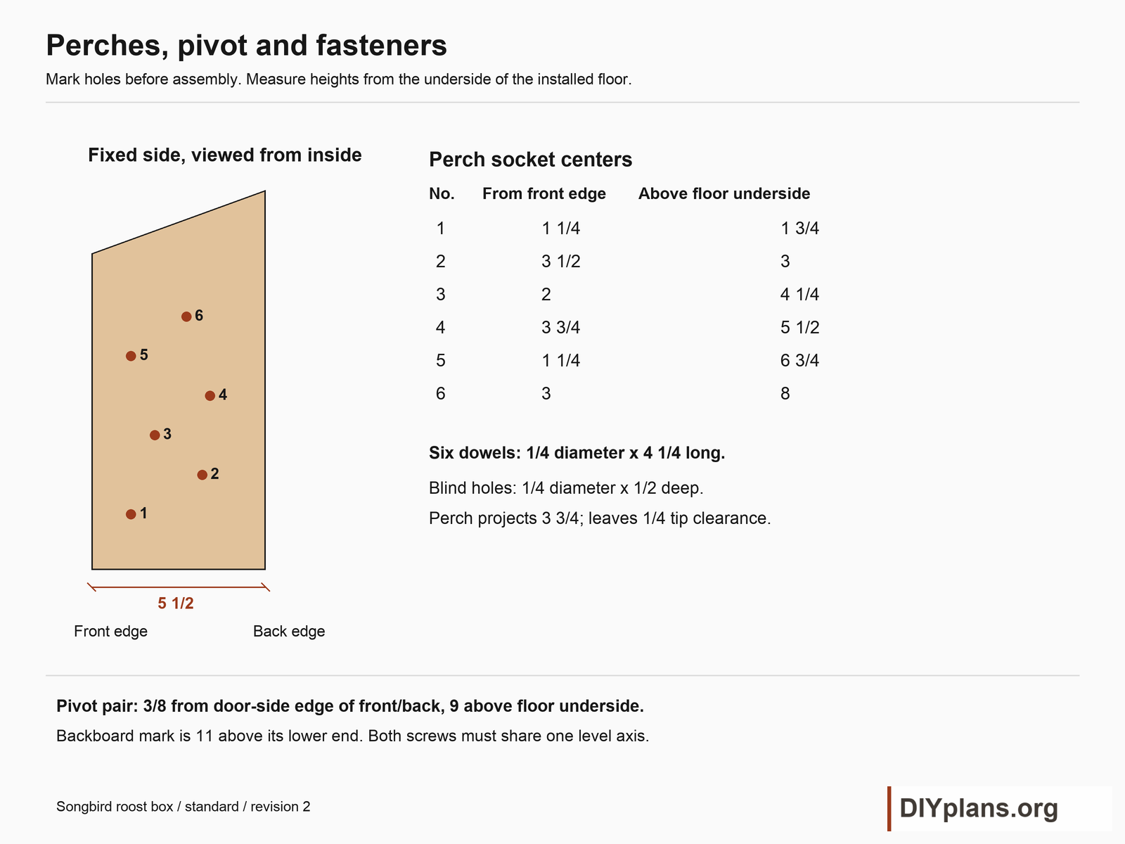
- On the fixed side only, mark the six socket centers shown in the hole drawing. Distances are from its front edge and bottom. Drill 1/4 diameter blind holes 1/2 deep with a depth stop; do not drill through.
- Drill two 5/16 clearance holes on the backboard centerline, 1 and 16 above its lower end. They are outside the chamber. Use pilot-hole sizes recommended for the mounting screws in the support.
Check: Entrance is clear, each socket leaves 1/4 wood behind it, and both mounting holes lie outside the enclosed chamber.
04 Fit and glue the perches
- Cut six dowels to 4 1/4 long. Use 1/4 diameter dowel to match the holes. Lightly roughen the dowels with coarse sandpaper and remove dust.
- Dry-fit each perch 1/2 into its socket. It should project 3 3/4 and leave 1/4 clearance to the closed side door. Do not substitute the six-inch dowels shown in the source sheet.
- Apply a small amount of exterior wood glue in each socket, seat the dowels, and wipe away squeeze-out. Let the glue fully cure before assembly or mounting.
Check: Six firm perches project 3 3/4; none touches the door or leaves an exposed sharp edge.
05 Assemble the fixed side, floor, back and front
- Mark a line 2 above the backboard lower end for the underside of the floor and the bottom of the side/front. Set the fixed side against the back, flush to its left edge. The 12 in side edge meets the back.
- Drill clearance holes through the outer board and pilot holes in the receiving wood. Start with about 9/64 clearance and 3/32 pilot for #6 screws in cedar, then test scrap and follow the screw maker. Countersink fixed heads flush; do not split the edges.
- Use three screws through the back into the fixed side, centered 3/8 from its left edge, at heights 2, 5 and 9 above the floor underside. Add two through the back into the floor at x=1 1/2 and 4, height 3/8. Add two through the fixed side into the floor, 1 1/2 and 4 from the side front edge, height 3/8.
- Fit the front over the side and floor ends, bottom flush with the floor underside. Repeat the three side screws and two floor screws through the front at the same x and height marks. This uses 12 fixed screws. Keep the right side open.
Check: The chamber is square, the floor is secure, and all four drainage corners remain open.
06 Trim and pivot the opening side
- Trim the door blank 1/32 off each front/rear edge, 1/16 off its bottom, and 1/8 below the matching top slope. Sand the upper corners round enough to clear the roof during rotation.
- Hold the door closed, outside face flush with the box right side. Mark a common pivot axis through front and back at x=5 1/8 across the box and 9 above floor underside. On the back, that height is 11 above its lower end. Clamp before drilling.

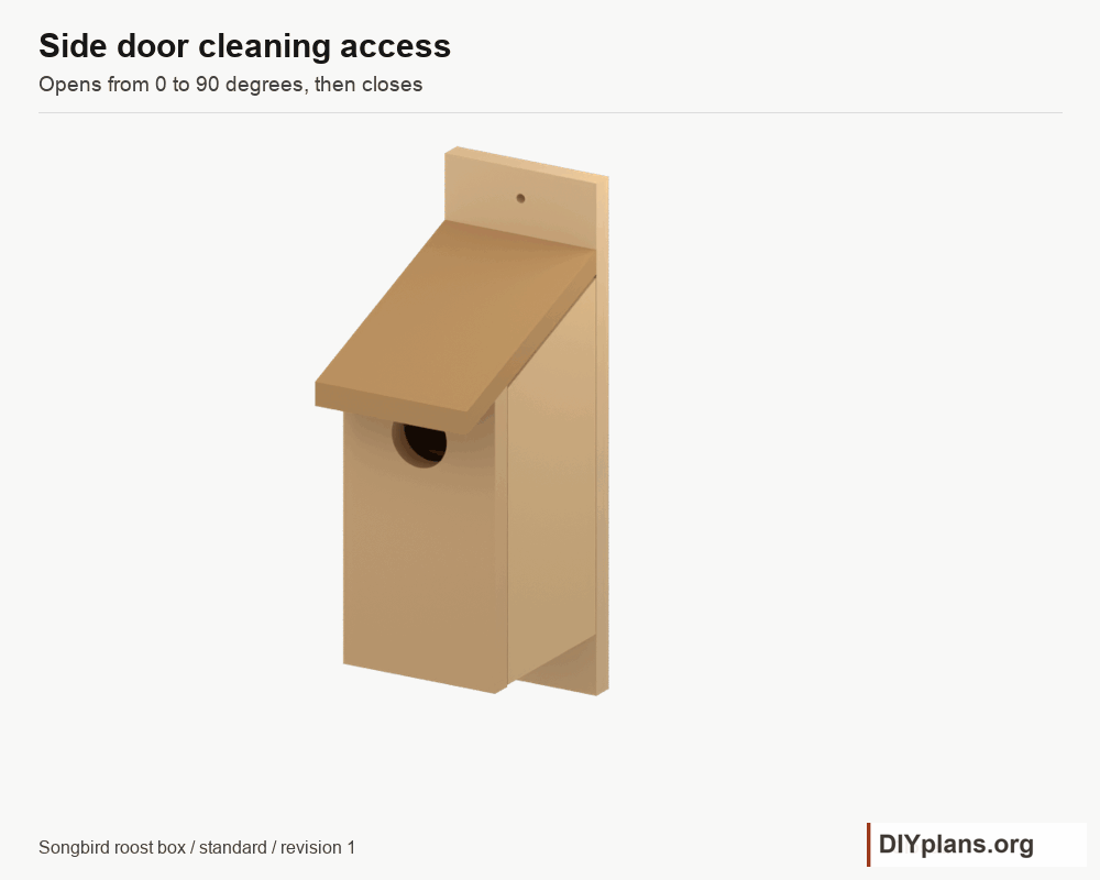
- Drill clearance holes through front/back and pilot holes into the door ends on this axis. Install one 1 1/4 screw from each end without clamping the door tight. The side bottom must swing out. Do not screw the floor or roof into the door.
Check: The side rotates freely outward to 90 degrees without striking a perch, floor or neighboring panel; both pivot screws stay engaged.
07 Attach the roof and secure the door
- Set the roof against the back. Use two screws down into the fixed-side top, 1 1/2 and 4 from its front edge, and two down into the front top at x=1 1/2 and 4. Place entries over the center of each receiving edge: 3/8 from the fixed-side outside face, and 3/8 behind the front outside face. Drill and drive vertically, parallel to the front and back, rather than perpendicular to the sloping roof. Keep the screw tips inside the boards. These four bring the fixed screw count to 16.
- Dry-fit the roof before driving the last screws. Check that the door still opens to 90 degrees under the roof. The rear bevel should close against the back without a water-catching gap.
- Place one small latch nail in the front near the door edge and one in the side near the front, both about 2 above floor underside. Use 3/4 in latch nails driven no more than 1/2 in, with points buried inside the wood. Drill small pilots and leave just enough head proud for the wire. Loop the wire around the heads so it cannot release accidentally. Fold sharp ends flat outside.
Check: There are 16 fixed screws and 2 pivots, the roof is seated, and the latch holds the door closed but releases for cleaning.
08 Mount and inspect the roost box
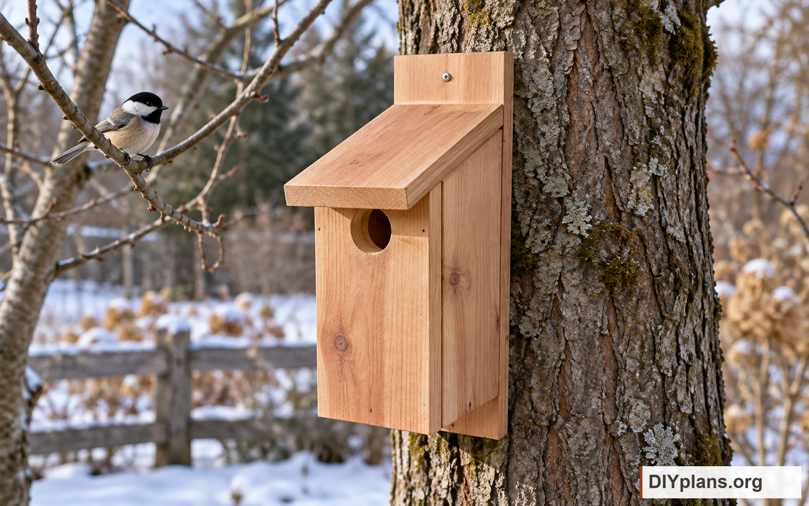
- Install only after the glue has cured. Choose a sheltered location with a clear flight path, away from prevailing wind and rain, and with safe access for maintenance. This high-entrance box provides roosting shelter; it is not a species-specific nest box.
- For an existing sound wood post, pilot-drill at the two backboard mounting holes, 15 apart. Fit the two #10 x 2 1/2 screws with washers and at least 1 1/2 embedment into sound wood. Do not crush the cedar by overtightening.
- Other supports need appropriate anchors and safe access chosen for that support. Keep wire or hardware clear of birds and account for tree growth if using a tree attachment. No post, footing, ladder setup or support capacity is specified by this box plan.
Check: The box cannot rock or rotate, the door stays shut, and no sharp fastener or wire projects into the chamber.
09 Clean and maintain the box
- Inspect when the box is unoccupied. Release the latch, swing the side out, remove old debris, and brush the floor and perches. Keep the drainage corners open. Let wet wood dry fully before closing.
- Check perch security, split wood, loose mounting screws and the latch at least seasonally and after severe weather. Repair defects before leaving the box available to birds.
- Leave the interior and perches untreated. The drawings show digital geometry; this package has not been physically built or field-tested. Observe whether local birds use it and keep it maintained.
Check: The dry box closes securely with clean perches and unobstructed drainage.
Sources
Based on dimensions in Washington Department of Fish and Wildlife, Roost Box for Songbirds. DIY Plans drew the CAD and illustrations and wrote these instructions. The compact board size, shorter perches, hole locations and door clearances are documented adaptations. WDFW has not reviewed or endorsed this package.