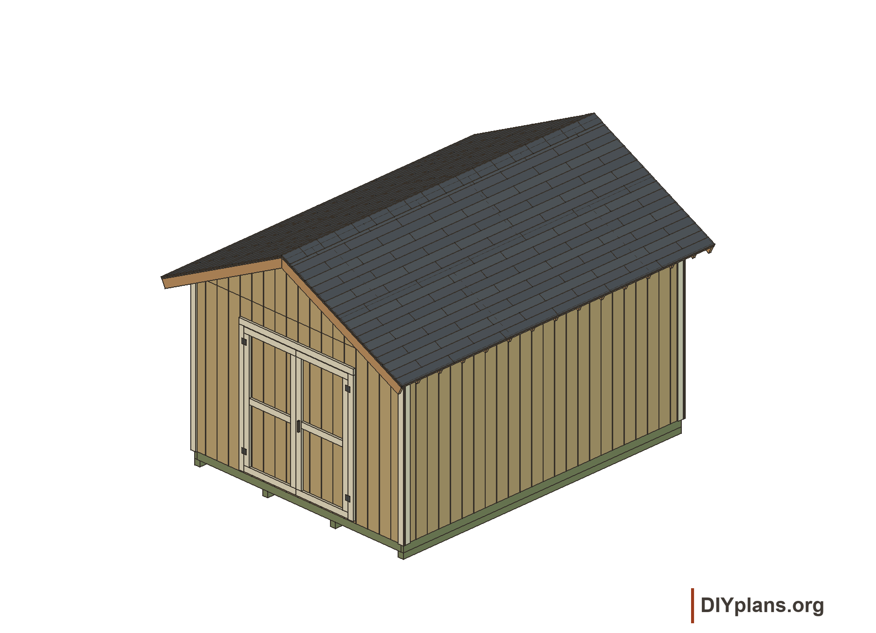
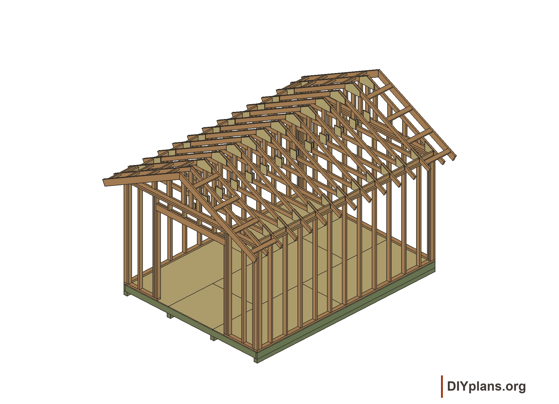
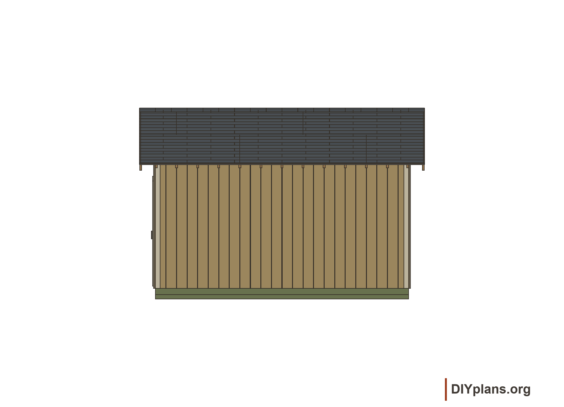
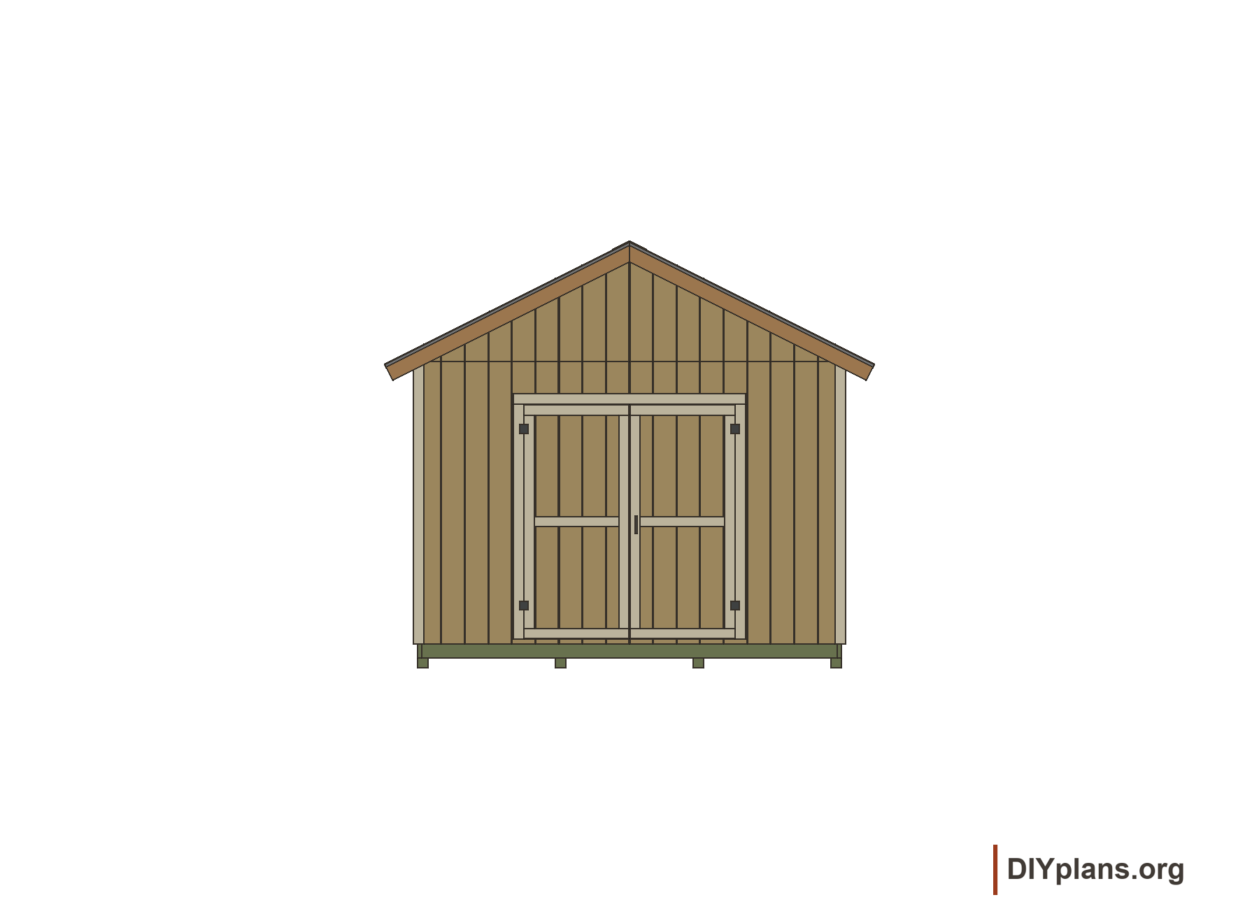
Dimensions and opening sizes
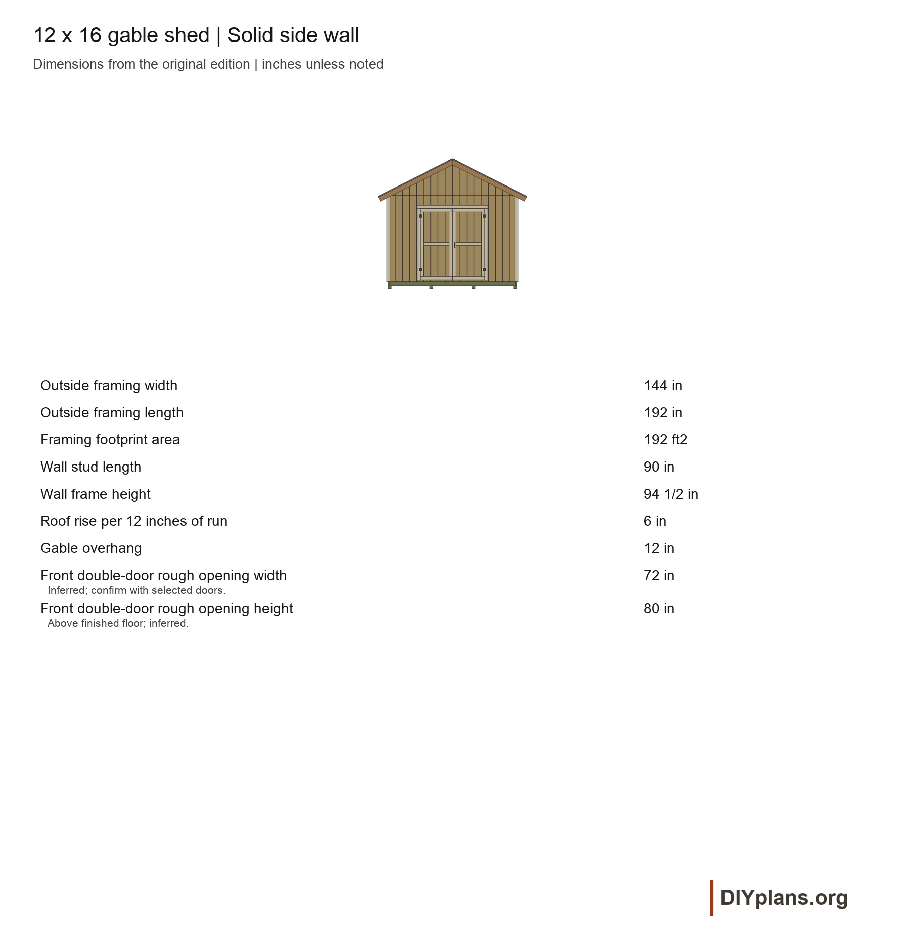
- Outside framing width
- 144 in
- Outside framing length
- 192 in
- Framing footprint area
- 192 ft²
- Wall stud length
- 90 in
- Wall frame height
- 94 1/2 in
- Roof rise per 12 inches of run
- 6 in
- Gable overhang
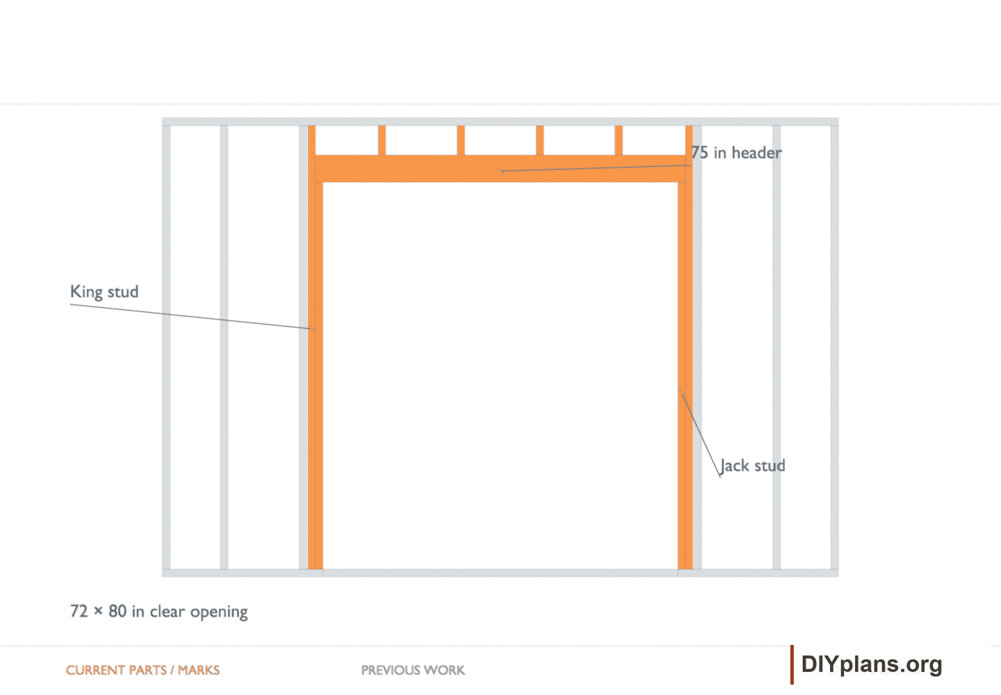
- 12 in
- Front double-door rough opening widthInferred; confirm with selected doors.
- 72 in
- Front double-door rough opening heightAbove finished floor; inferred.
- 80 in
Shopping & cut lists
Get the shopping and cut lists
Includes all available CAD files, shopping lists and cut lists for every configuration of this plan. One payment, $19 USD.
Get the plan package · $19Secure checkout with Stripe. Your account is created after payment.
Already purchased? Sign in to access your plans.
Tools & equipment
- Tape measure, framing square and chalk line
- Long level and straightedge
- Circular saw or miter saw
- Jigsaw for shaped panel cuts
- Drill/driver and bits
- Clamps, sawhorses and assembly supports
- Fastening and roofing tools for the selected products
- Temporary wall and roof bracing
- Lifting equipment and safe roof access
- Eye, hearing and dust protection
BEFORE YOU BUILD
Use this work at your own risk
No person or organization makes any guarantee or warranty, express or implied, regarding this design, its documentation, digital files, or website views. They are not professional services and do not create an architect-client or other professional-client relationship. No promise is made about accuracy, completeness, reliability, code compliance, or fitness for your project.
Buildings and building projects are complex, and many things can go wrong. You are responsible for checking dimensions and site conditions, choosing suitable materials and methods, obtaining permits, following codes and manufacturer instructions, and getting qualified professional help when needed. To the fullest extent permitted by law, DIYPlans.org disclaims liability for damages resulting from use of this work. Read the FAQ about your responsibilities.
Instructions

01 Mark the footprint
- Have the foundation, anchors, design loads, lumber grades, connections and bracing specified for your site before buying or cutting materials. This package does not include a completed structural design.
- Check the site for drainage and clearance around the doors and roof overhangs.
- Mark a rectangle 144 in across the front and 192 in along the sides. These lines locate the outside faces of the floor framing.
- Measure both diagonals. Adjust the corners until each diagonal measures 240 in.
- Label the 144 in end with the double doors as the front. Measure all lengthwise positions from this end.
Check: The framing lines measure 144 × 192 in, with two equal 240 in diagonals.
02 Set the four skids
- Prepare level, drained bearing points to the foundation design. Use its specified ground clearance and anchors.
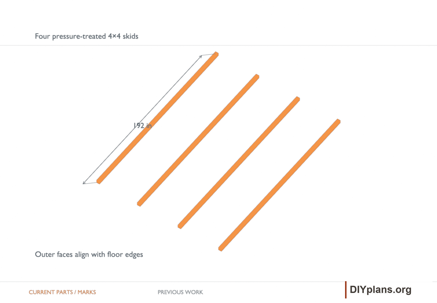
- Place four pressure-treated 4×4 skids, each 192 in long, parallel to the long sides. The dressed skid size is 3 1/2 × 3 1/2 in.
- Align the outer skid faces with the two long framing lines. Space the two middle skids equally between them.
- Check the skid tops for level and full support before adding the floor frame.
Check: All four skids are supported, parallel and level, with their ends aligned at the front and rear.
03 Mark the joist positions
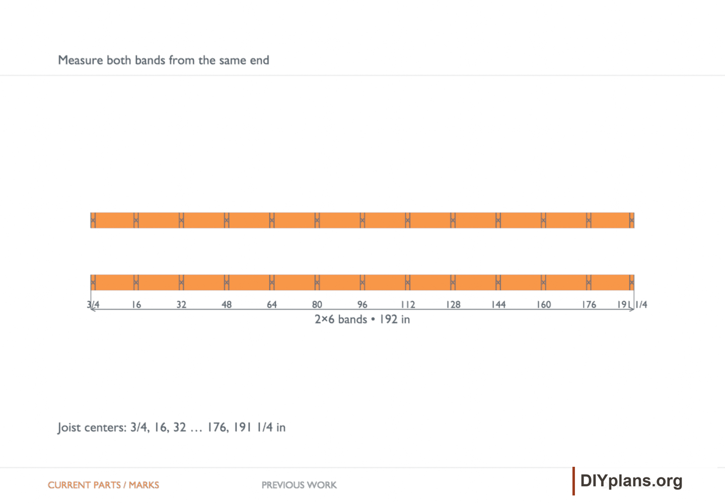
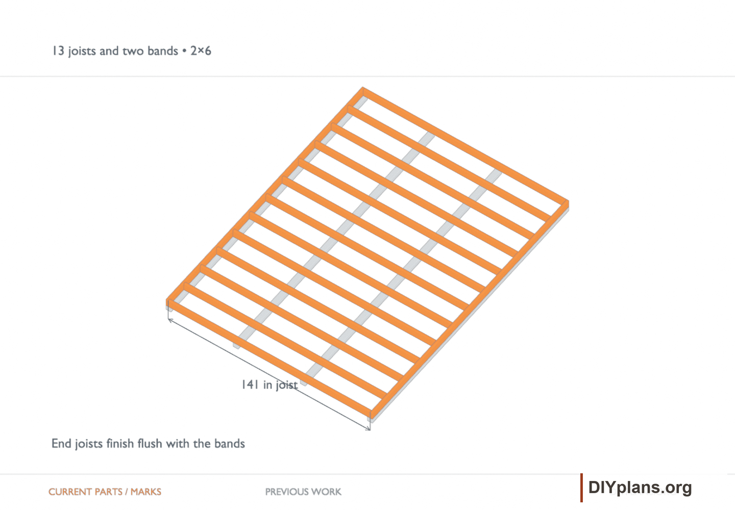
- Cut two pressure-treated 2×6 band boards to 192 in and thirteen pressure-treated 2×6 joists to 141 in. The dressed 2×6 size is 1 1/2 × 5 1/2 in.
- Place the band boards side by side with their front ends flush. Mark the same front reference end on both boards.
- Measure the joist centers from that end at 3/4, 16, 32, 48, 64, 80, 96, 112, 128, 144, 160, 176 and 191 1/4 in.
- Use a square to mark each joist's two edges, 3/4 in to either side of its center. Mark an X between the lines.
Check: Both bands have matching joist marks, with the first and last joists flush with their ends.
04 Assemble the floor frame
- Set the band boards on the outer skids with their marked front ends together.
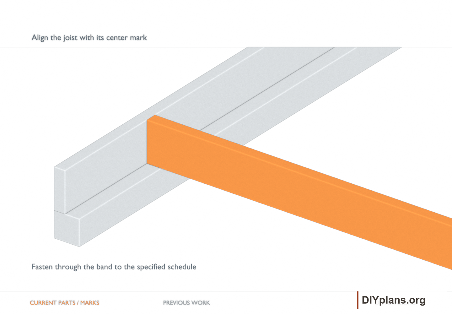
- Fit the thirteen 141 in joists between the bands at the marks. Keep the two end joists flush with the band ends.
- Check the outside dimensions at 144 × 192 in, then adjust the frame until both diagonals measure 240 in.
- Fasten the joists, bands and foundation connections using the specified connection and anchorage schedule.
Check: The frame is square, supported on all four skids and secured with the specified connections.
05 Lay the floor panels
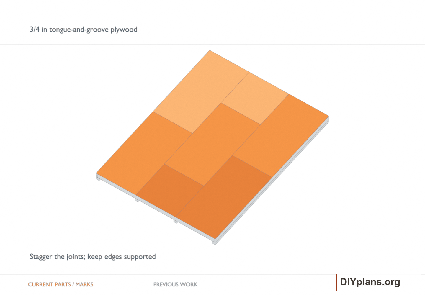
- Dry-lay the 3/4 in tongue-and-groove plywood with its required strength direction across the joists.
- Cut the panels to the staggered layout. Keep the perimeter flush with the floor framing and provide the required support at panel joints.
- Leave the panel manufacturer's expansion gaps. Seat the tongue-and-groove joints without forcing them closed.
- Fasten the panels to the specified schedule. Keep the deck flat for laying out the walls.
Check: The floor is flat, its panel joints are supported and staggered, and its top is 9 3/4 in above the skid bottoms.
06 Cut and label the wall plates
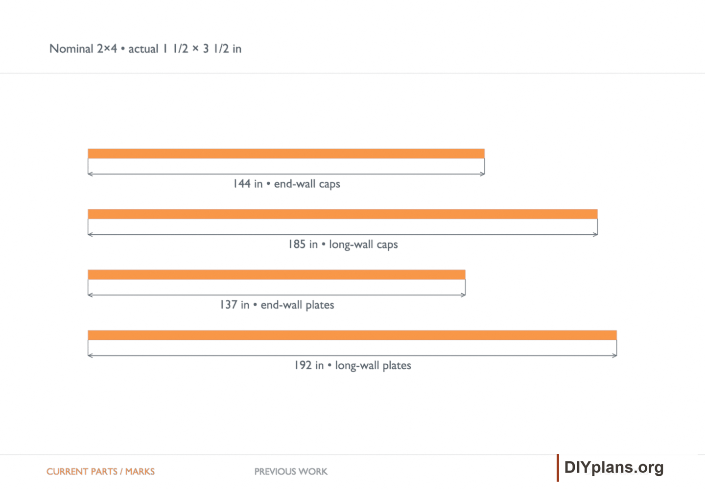
- Use nominal 2×4 stock with a dressed size of 1 1/2 × 3 1/2 in.
- Cut the long-wall bottom and first top plates to 192 in. Cut the end-wall bottom and first top plates to 137 in so the end walls fit between the long walls.
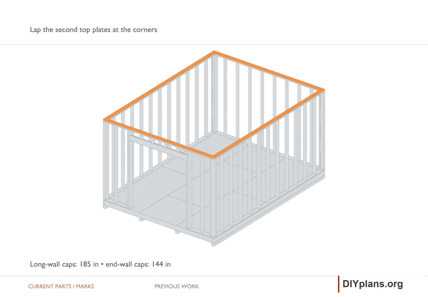
- Cut the second top plates, called caps, to 185 in for the long walls and 144 in for the end walls.
- Label each plate Front, Rear, Side or Opposite side, and mark its reference end. Set the caps aside until the walls are standing.
Check: Each wall has its own labeled plate pair, and the four caps are separate.
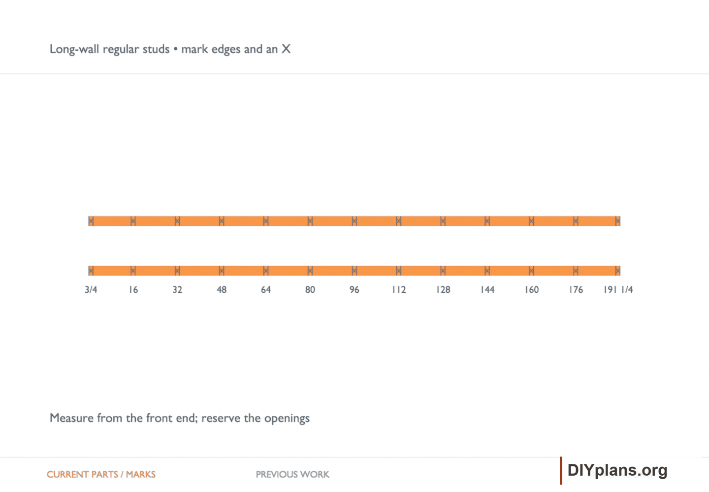
07 Mark the side-wall studs
- Place each bottom plate beside its first top plate with the reference ends flush.
- Mark the side wall's regular-stud centers at 3/4, 16, 32, 48, 64, 80, 96, 112, 128, 144, 160, 176 and 191 1/4 in from the front end.
- Square each stud's two edges across both plates, 3/4 in to either side of its center, and mark an X between the lines.
Check: The two plates have matching stud marks measured from the same reference end.
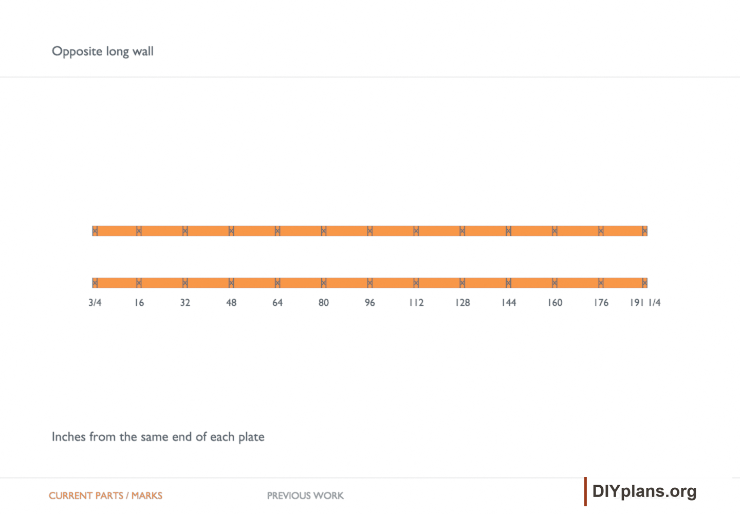
08 Mark the opposite-wall studs
- Place each bottom plate beside its first top plate with the reference ends flush.
- Mark the opposite wall's regular-stud centers at 3/4, 16, 32, 48, 64, 80, 96, 112, 128, 144, 160, 176 and 191 1/4 in from the front end.
- Square each stud's two edges across both plates, 3/4 in to either side of its center, and mark an X between the lines.
Check: The two plates have matching stud marks measured from the same reference end.
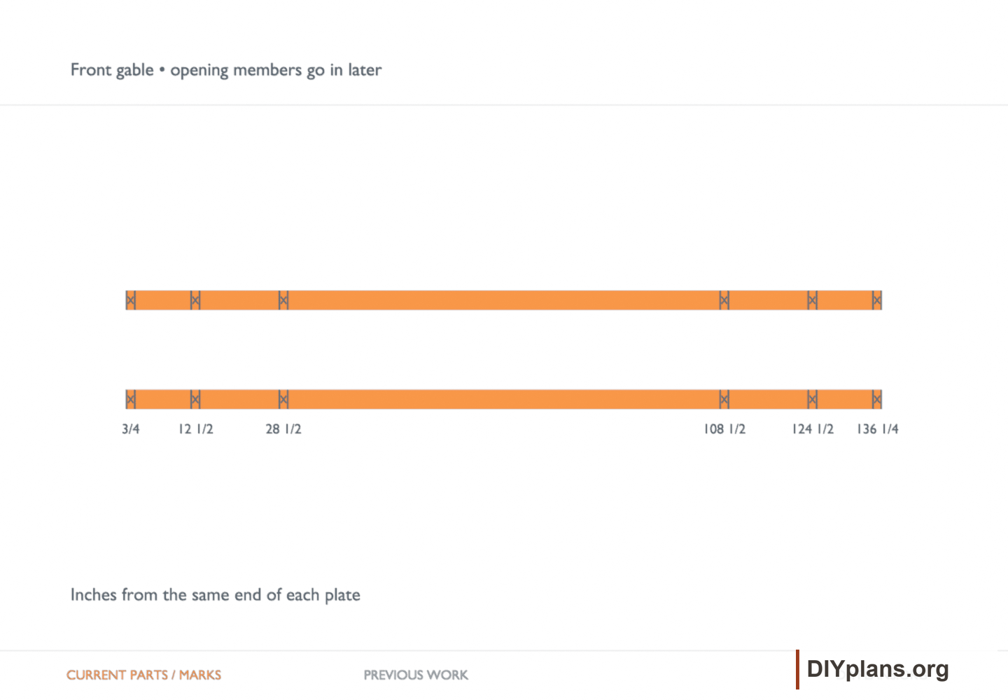
09 Mark the front-wall studs
- Place each bottom plate beside its first top plate with the reference ends flush.
- Mark the front gable plate's regular-stud centers at 3/4, 12 1/2, 28 1/2, 108 1/2, 124 1/2 and 136 1/4 in from its end. Leave the double-door area clear.
- Square each stud's two edges across both plates, 3/4 in to either side of its center, and mark an X between the lines.
Check: The two plates have matching stud marks measured from the same reference end.
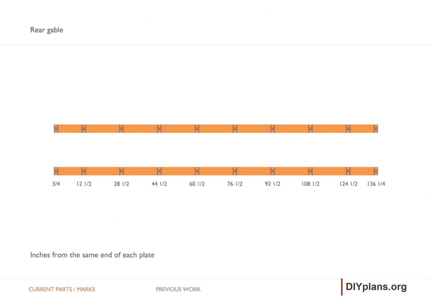
10 Mark the rear-wall studs
- Place each bottom plate beside its first top plate with the reference ends flush.
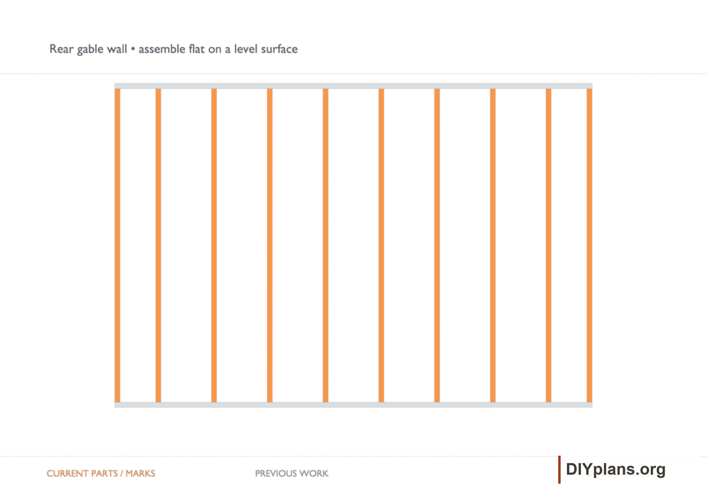
- Mark the rear gable plate's regular-stud centers at 3/4, 12 1/2, 28 1/2, 44 1/2, 60 1/2, 76 1/2, 92 1/2, 108 1/2, 124 1/2 and 136 1/4 in from its end.
- Square each stud's two edges across both plates, 3/4 in to either side of its center, and mark an X between the lines.
Check: The two plates have matching stud marks measured from the same reference end.
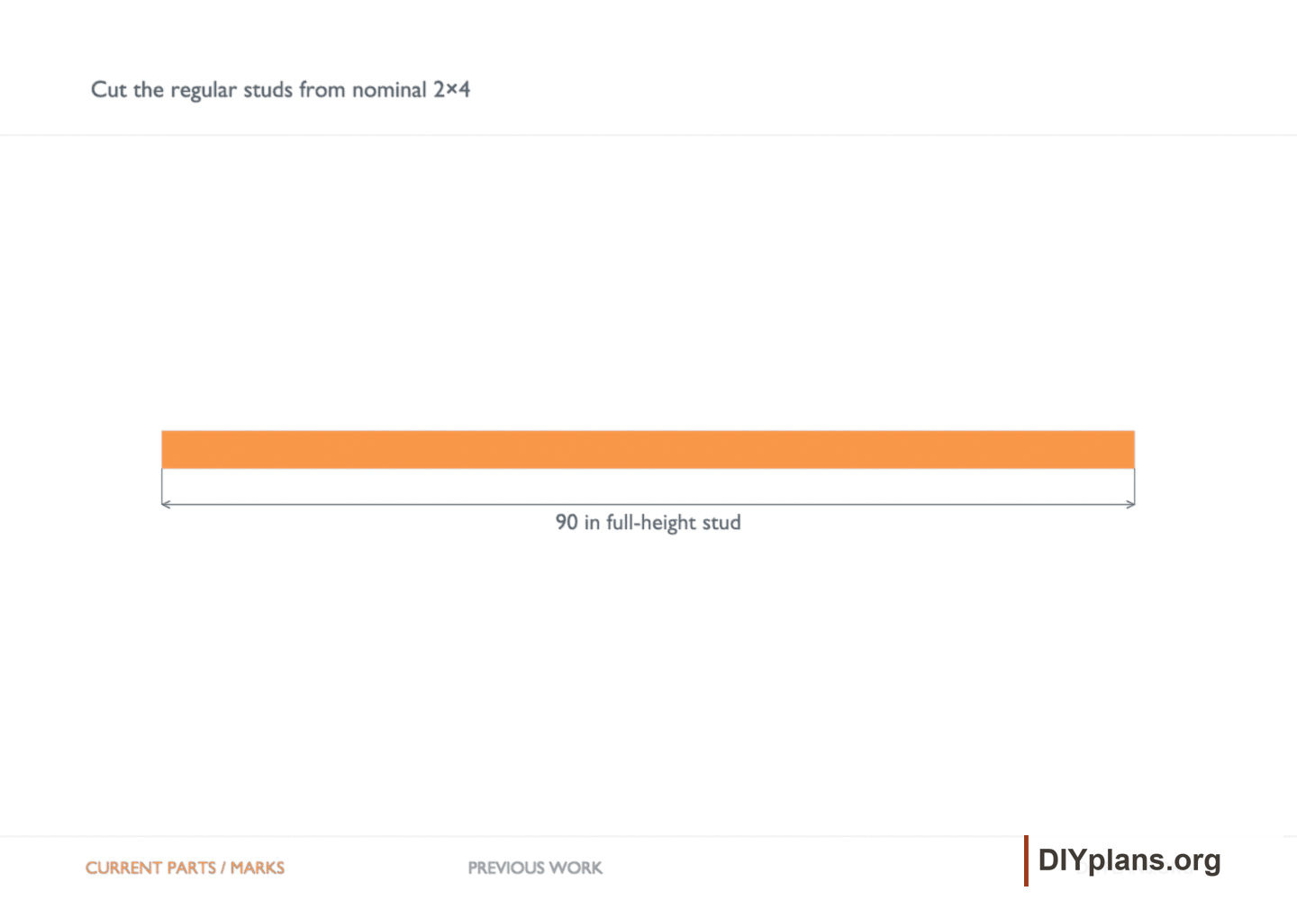
11 Cut the full-height studs
- Cut the full-height studs to 90 in from nominal 2×4 stock.
- Check the first stud, then use it to set a stop for the remaining cuts.
- Keep the shorter opening members separate until their framing steps.
Check: The full-height studs are 90 in long with square ends.


12 Assemble the wall frames
- Lay each wall's bottom and first top plates on edge, with their stud marks facing one another.
- Fit the regular 90 in studs at their marked positions, matching each frame to its labeled layout. Leave the reserved opening areas empty.
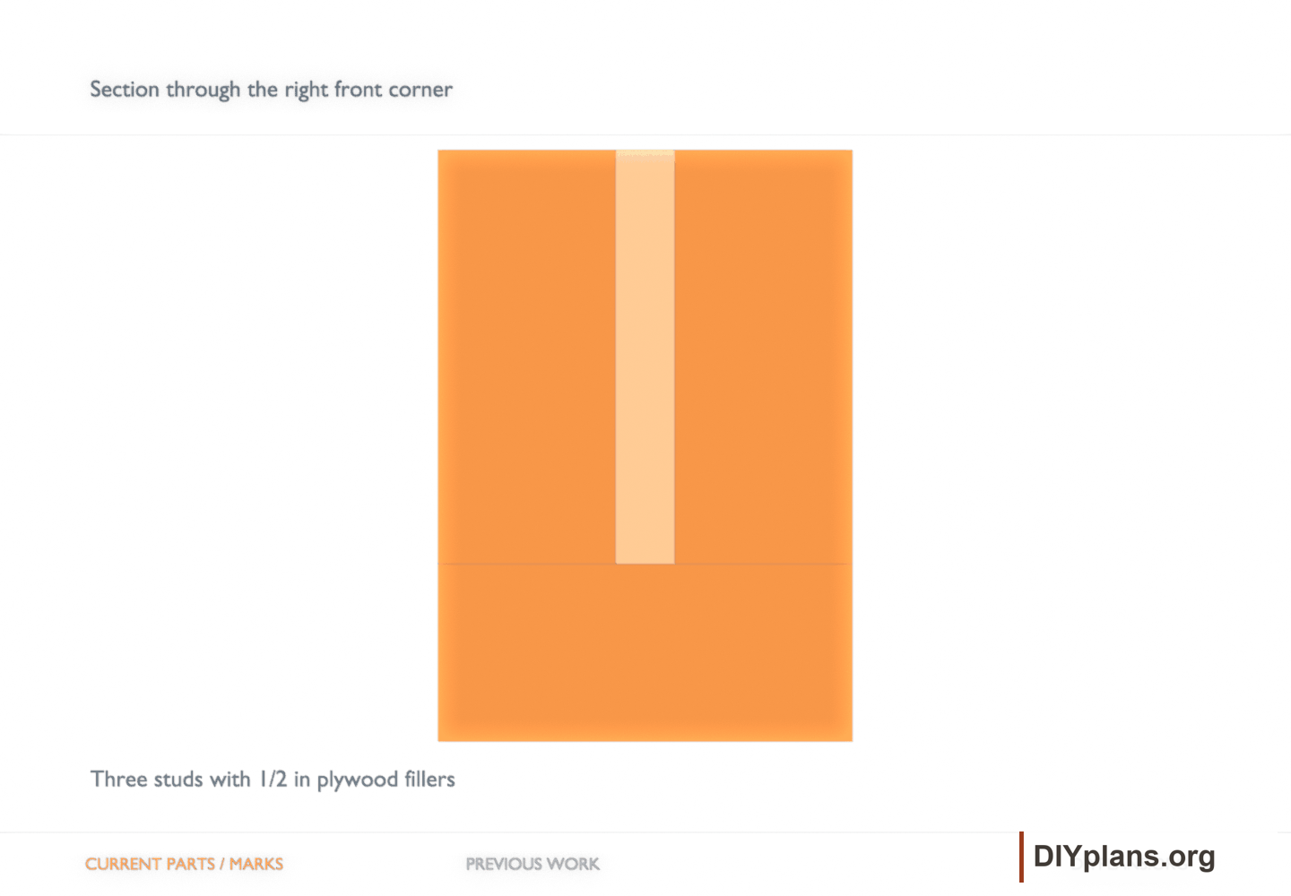
- Assemble the three-stud corner packs with their 1/2 in plywood fillers, using the corner detail to orient the extra studs.
- Square each frame and fasten its joints to the connection schedule. Keep the second top plates aside.
Check: The regular studs and corner packs are installed. Opening framing and the second top plates are still absent.
13 Mark the front doorway
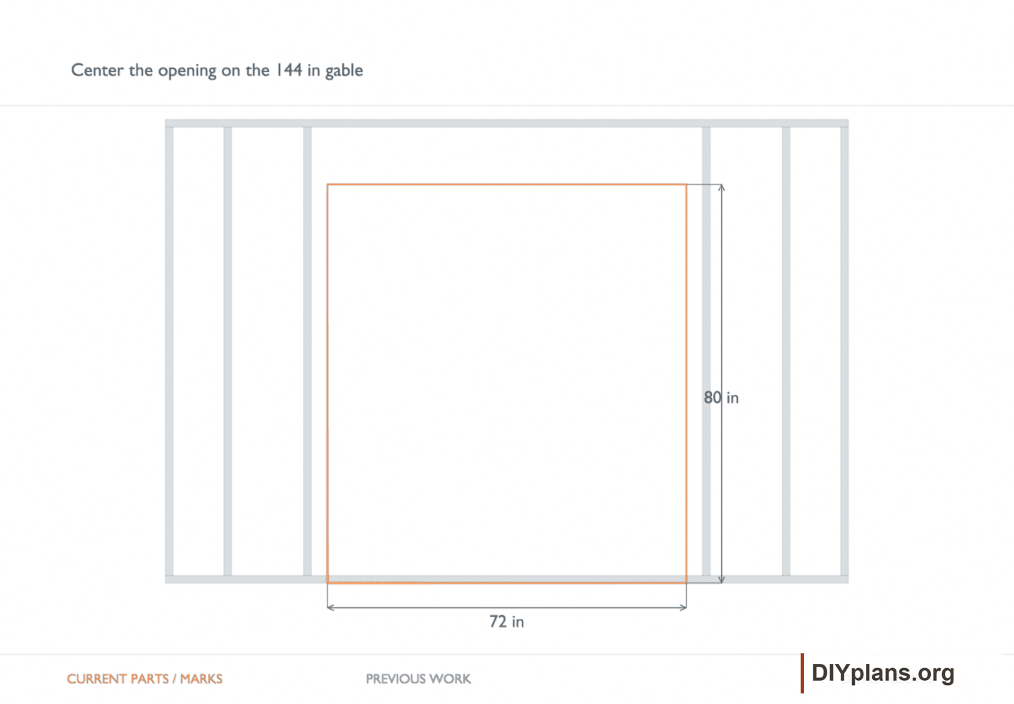
- Confirm the double-door and threshold details before fixing the proposed 72 × 80 in rough opening.
- Mark the building center at 72 in across the front. Measure from the outside of the long-wall framing, not from the end of the shorter gable-wall plate.
- Mark the opening edges at 36 and 108 in across the building. The same edges are 32 1/2 and 104 1/2 in from the end of the 137 in gable-wall plate.
- Mark the header's underside 80 in above the finished floor, then transfer the king- and jack-stud positions onto the plate pair.
Check: The marked opening is 72 in wide, centered across the building and 80 in high above the floor.
14 Frame the front doorway
- Have the header and its connections specified before fabricating the doorway.
- Fit the 90 in king studs outside the opening and the 78 1/2 in jack studs against their inner faces.
- Assemble the header from two 75 in 2×6 plies and a 1/2 in plywood spacer. Seat the header on the jack studs.
- Fit the upper cripple studs at their drawing positions. Fasten the header, studs and plates to the connection schedule.
- Mark the bottom-plate cuts at the opening edges, leaving a 32 1/2 in section at each end. Keep the doorway section in place until the wall is secured, or use the specified temporary brace across the opening.
Check: The header bears on both jack studs and leaves a centered 72 × 80 in opening above the finished floor.
Play movementStop movement

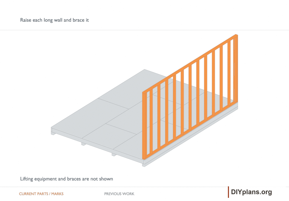
15 Raise the long walls
- Arrange enough helpers or lifting equipment for each wall. Prepare temporary braces and their attachment points before lifting.
- Raise the first 192 in wall onto its floor-framing line. Keep its bottom plate aligned with the outside edge of the floor.
- Plumb the wall, attach the specified base connections and secure its temporary braces before releasing it.
- Raise and brace the opposite long wall in the same way. Keep the end-wall spaces clear.
Check: Both long walls are plumb and securely braced, with their ends aligned at the front and rear.
Play movementStop movement

16 Raise the end walls
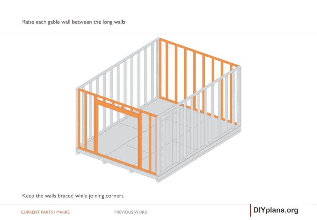
- Raise the rear wall into the space between the long walls. Align its outside face with the rear edge of the floor.
- Plumb and brace the rear wall, then connect its base and corners to the specified schedule.
- Raise the front doorway wall between the long walls. Align, plumb, brace and connect it in the same way.
- Recheck the building diagonals and all opening dimensions before tying the wall tops together.
Check: All four walls are plumb, square and connected at the corners, with temporary bracing still secure.
17 Lap the top plates
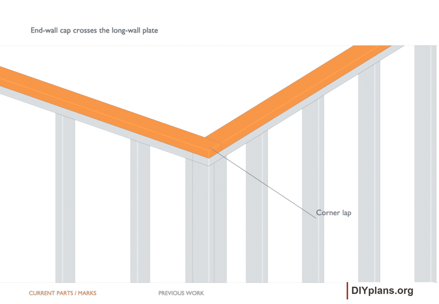
- Place the 185 in caps on the long walls and the 144 in caps across the end walls, following the corner laps shown.
- Seat each cap flat and align its edges with the wall below. Fasten the laps and plate runs to the connection schedule.
- Check the finished wall-frame height at 94 1/2 in above the floor. Recheck the walls for plumb and straightness.
- After the walls are secured, remove any bottom-plate section spanning a doorway without cutting into the floor. Retain the required temporary bracing.
Check: The caps lap the wall corners and form a straight, level roof-bearing line 104 1/4 in above the skid bottoms.
18 Lay out the first truss
- Have the truss members, gusset shapes, connections and bracing specified before fabrication. Use that completed design for the cuts and fasteners.
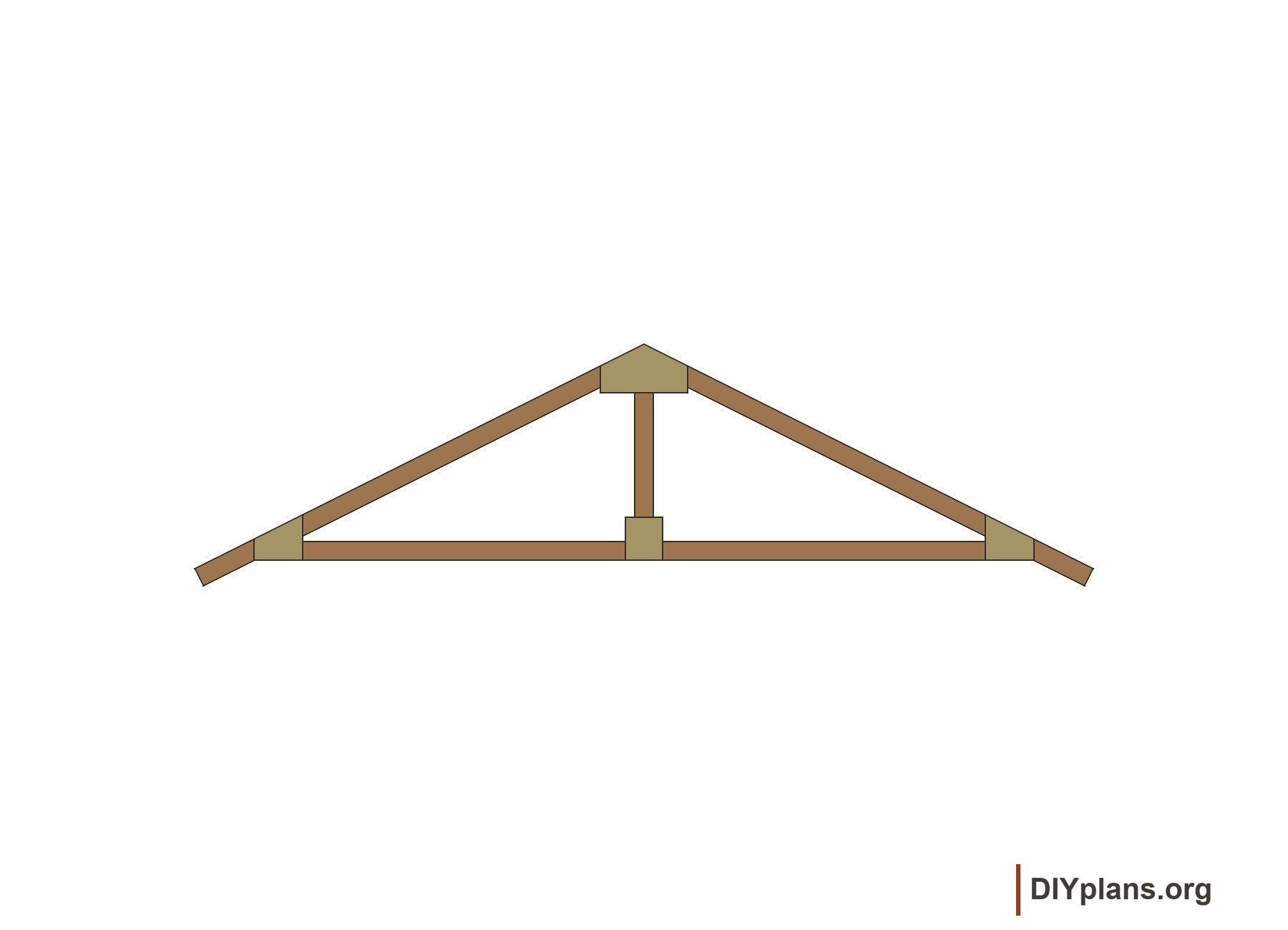
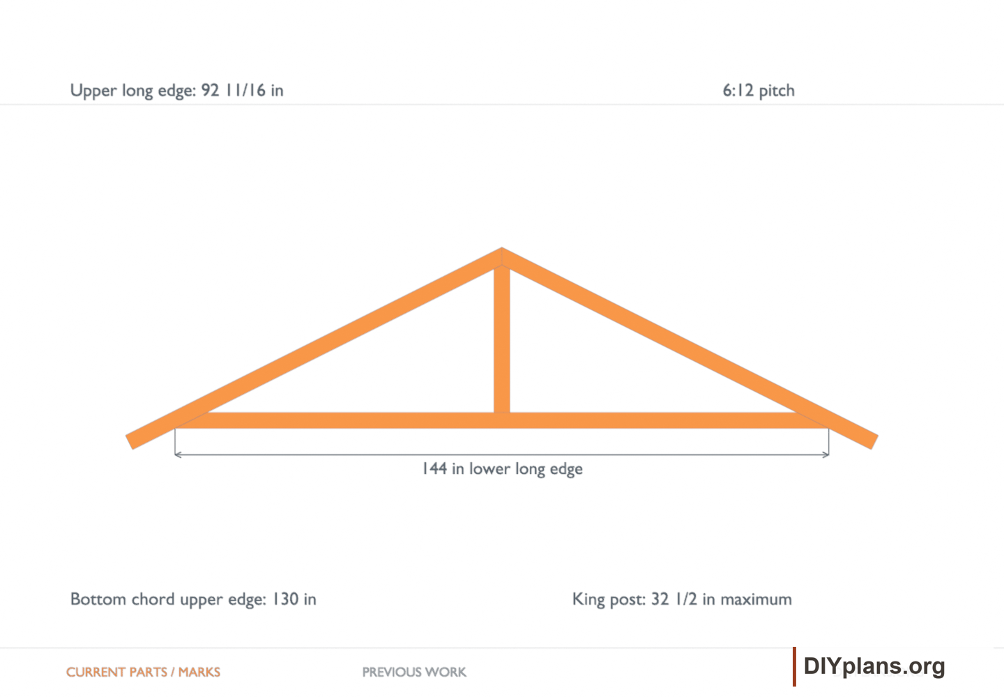
- Mark a full-size 6:12 roof layout on a flat work surface. Mark the centerline and the 144 in lower edge of the bottom chord.
- Lay out the two sloping 2×4 upper chords with 92 11/16 in long upper edges. Mark the horizontal bottom chord's 144 in lower edge, 130 in upper edge and beveled ends.
- Lay out the center upright, called the king post, to its 32 1/2 in maximum height. Dry-fit the cut members to the layout and check both roof slopes.
- Use the checked pattern to prepare thirteen matching truss sets. Keep the two end trusses identified.
Check: The first dry-fitted truss matches the full-size layout, with all joints seated and the centerline aligned.
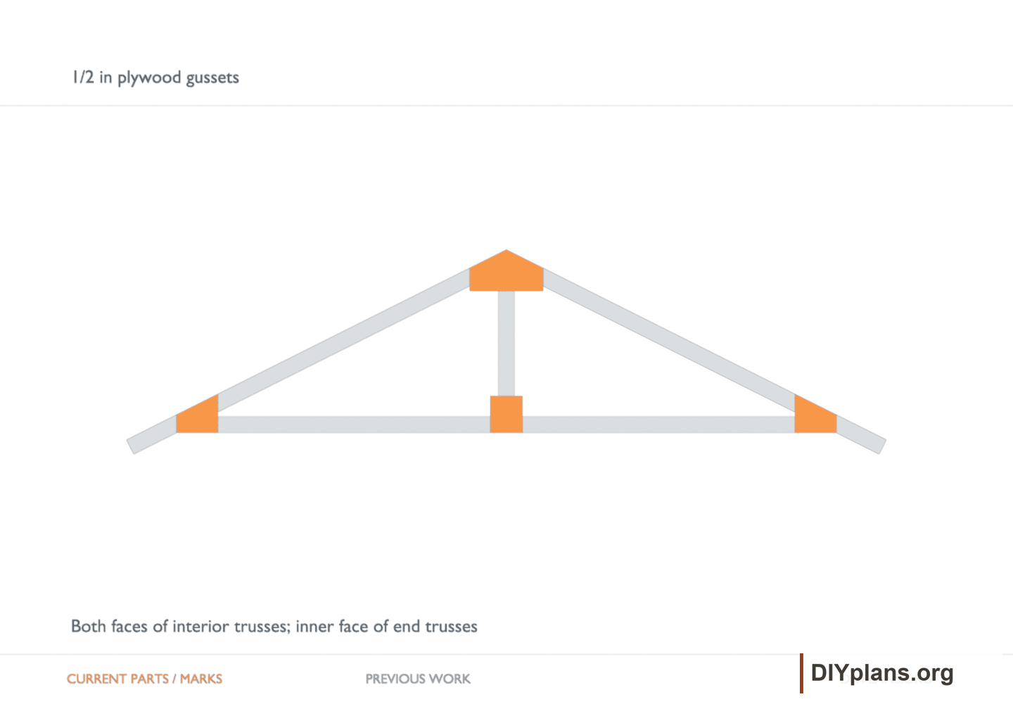
19 Fit the truss gussets
- Cut the 1/2 in plywood gussets to the specified shapes. Use the required plywood grade and fastening schedule.
- Hold the truss members against the full-size layout and fit the gussets over the joints.
- Fit gussets to both faces of the eleven interior trusses. Fit them to the inner faces of the two end trusses.
- Check each truss against the first one, then label the front and rear end trusses so their gussets face inward when installed.
Check: All thirteen trusses have the specified gussets, with the end-truss outer faces clear.
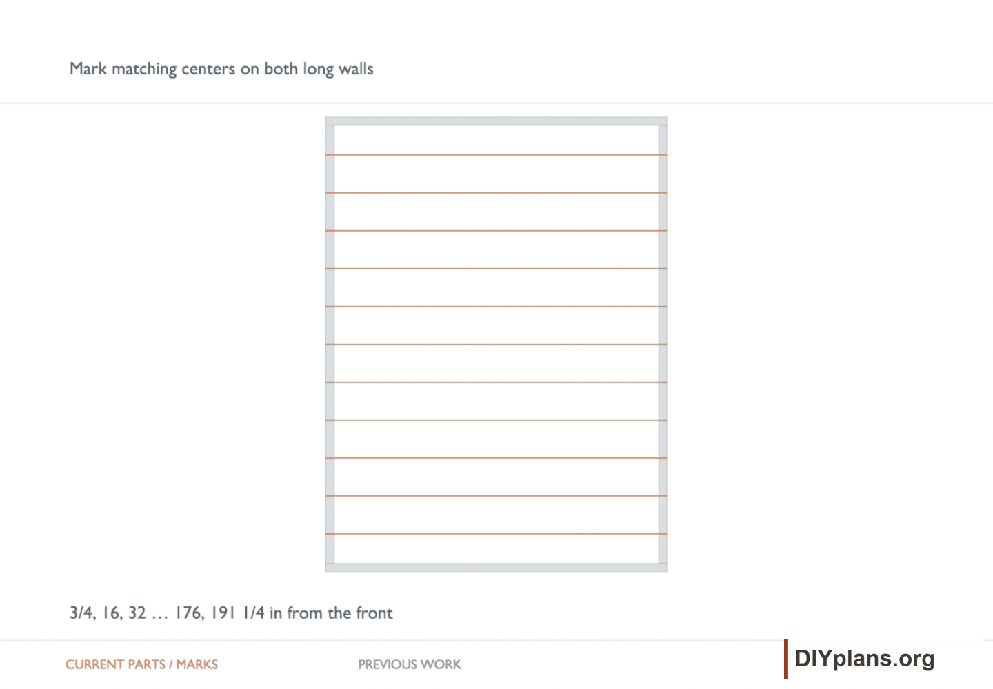
20 Mark the truss positions
- Measure from the front framing plane along each long-wall cap.
- Mark truss centers at 3/4, 16, 32, 48, 64, 80, 96, 112, 128, 144, 160, 176 and 191 1/4 in.
- Mark both faces of each 1 1/2 in thick truss on the caps. Keep the front and rear end trusses flush with the framing ends.
- Prepare the specified truss connections and temporary roof bracing before lifting.
Check: Both caps have thirteen matching truss positions measured from the same front reference.
Play movementStop movement

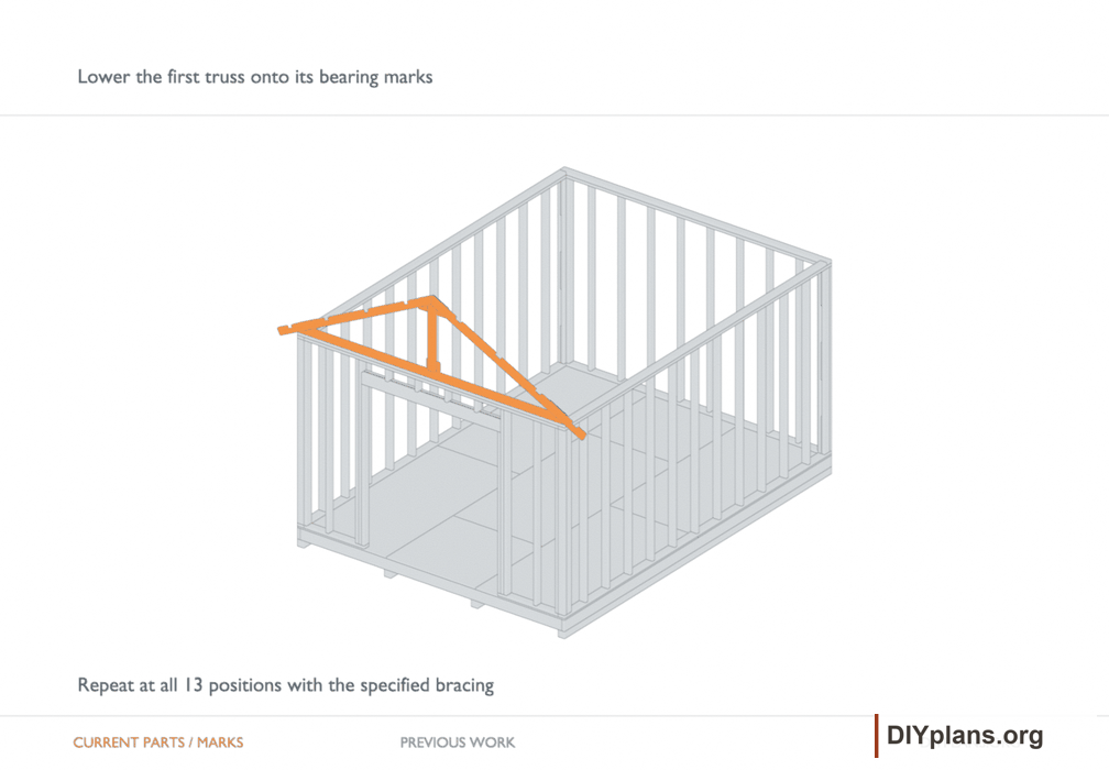
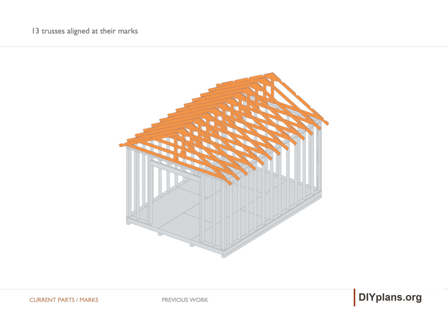
21 Set and brace the trusses
- Follow the planned lifting method with enough help and the specified temporary bracing ready. Keep people clear beneath suspended trusses.
- Set the first end truss on its marks with its gussets facing into the shed. Plumb it and secure its temporary braces and bearing connections.
- Place the remaining trusses at the matching marks. Keep the ridge straight and the trusses plumb as you add the specified bracing and connections.
- Fit the rear end truss with its gussets facing inward. Keep temporary bracing until the required permanent bracing and connections are complete.
Check: Thirteen trusses align with their marks and form two straight roof planes, with the required bracing and connections installed.
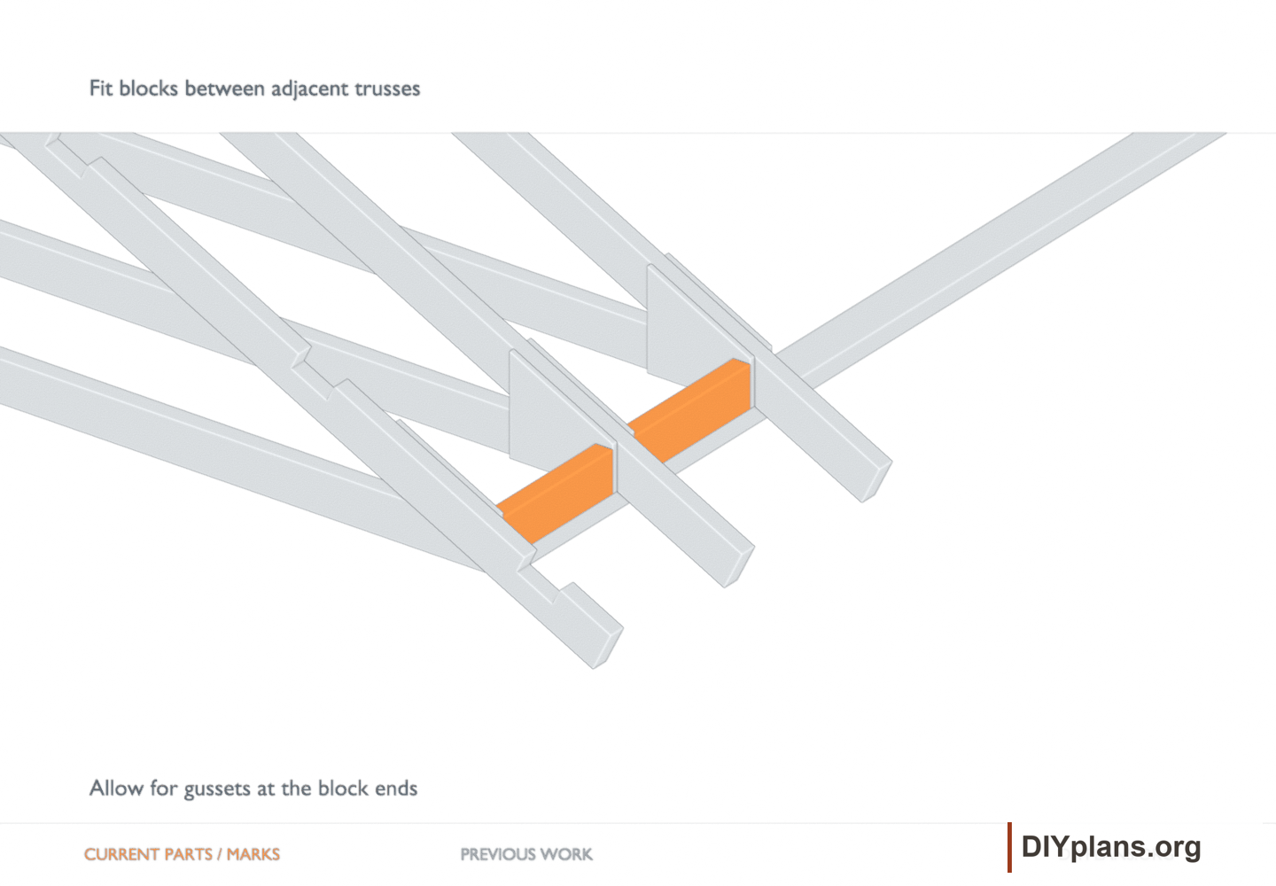
22 Fit the eave blocks
- Lay out the 24 eave blocks between trusses, one row along each long wall.
- Cut each block to its actual gap. Shorten blocks where the truss gussets occupy the adjoining faces.
- Set the blocks in the orientation shown and fasten them with the specified connections.
- Keep any ventilation paths required by the roof design open.
Check: Both eaves have their blocks fitted without forcing the trusses out of line.
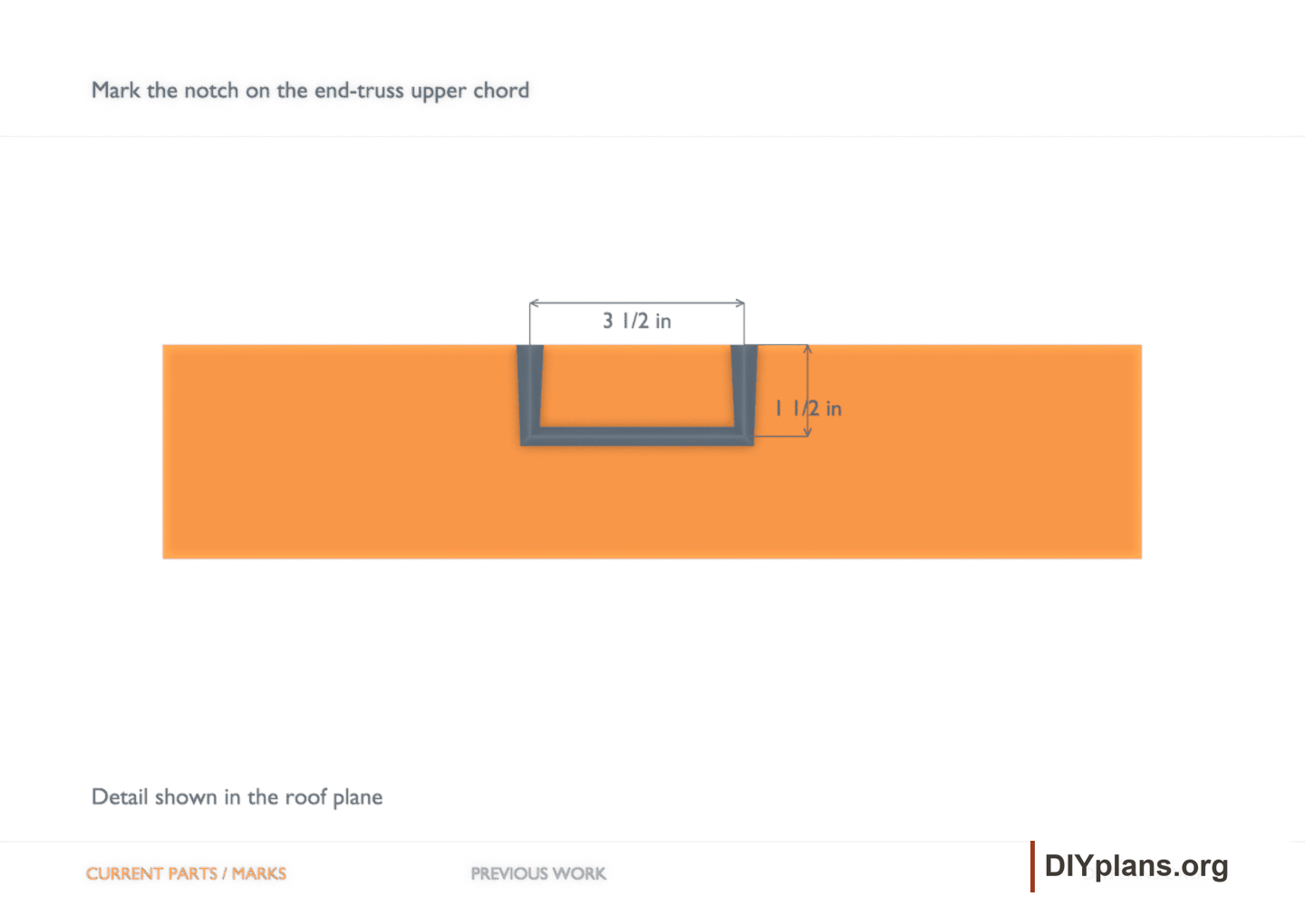
23 Mark the overhang cuts
- Have the outrigger notches and connections checked as part of the roof design before cutting the end trusses.
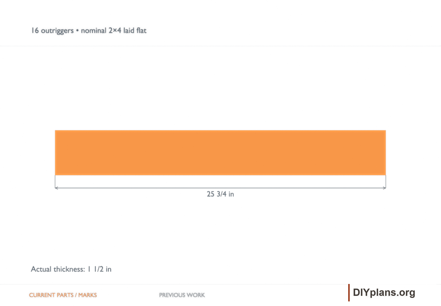
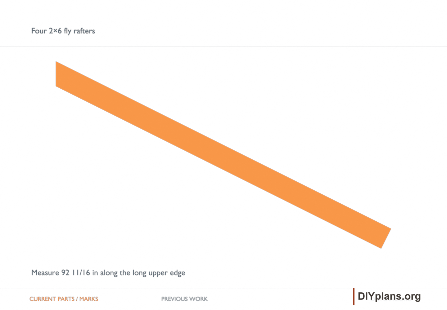
- Mark sixteen flat 2×4 outriggers at 25 3/4 in. Mark four 2×6 fly rafters with 92 11/16 in long upper edges.
- Transfer the outrigger positions to the end-truss upper chords. Mark each notch 1 1/2 in deep by 3 1/2 in wide in the roof plane.
- Check the notch orientation and depth against the joint detail, then make the specified cuts.
Check: The outrigger stock is cut to length, and the end-truss notches match the roof-plane detail.
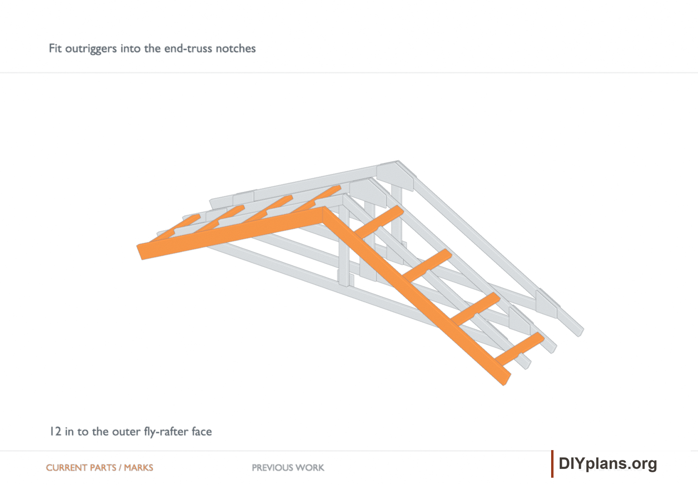
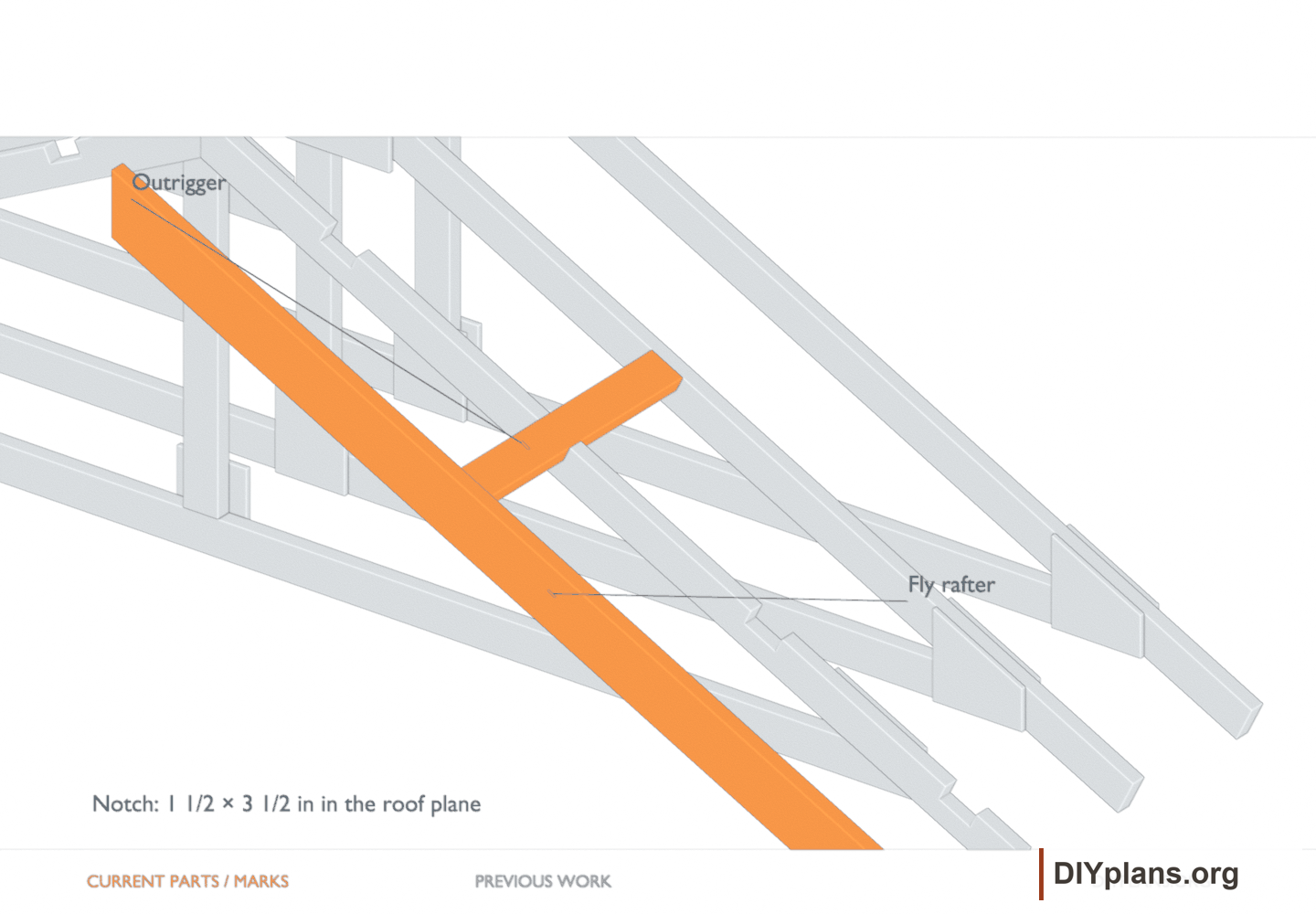
24 Install the gable overhangs
- Fit the sixteen outriggers at the marked positions, using the specified inward bearing and connections.
- Align their top faces with the roof plane. Attach the four fly rafters, the outermost sloping roof boards, to the outrigger ends.
- Measure the gable overhang from the end-wall framing plane to the outside face of the fly rafters. Set it to 12 in.
- Sight along both roof planes and complete the specified overhang connections.
Check: Both gables have straight 12 in overhangs, with the fly rafters aligned to the roof slopes.
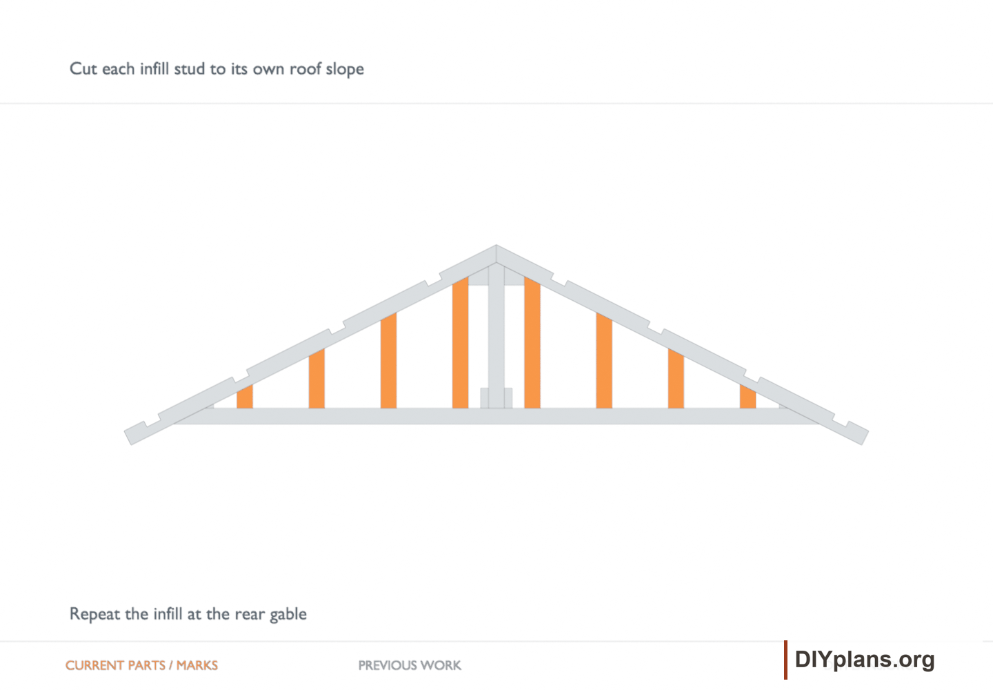
25 Fit the gable studs
- Transfer the gable-stud positions from the framing layout onto the front and rear end walls.
- Measure and cut the sixteen infill studs to their individual lengths and sloped top cuts.
- Fit the studs below the end-truss upper chords, keeping their outside faces flush with the gable framing.
- Fasten the infill members to the specified connection schedule.
Check: Both gables have their eight infill studs fitted, with sloped ends seated beneath the roof framing.
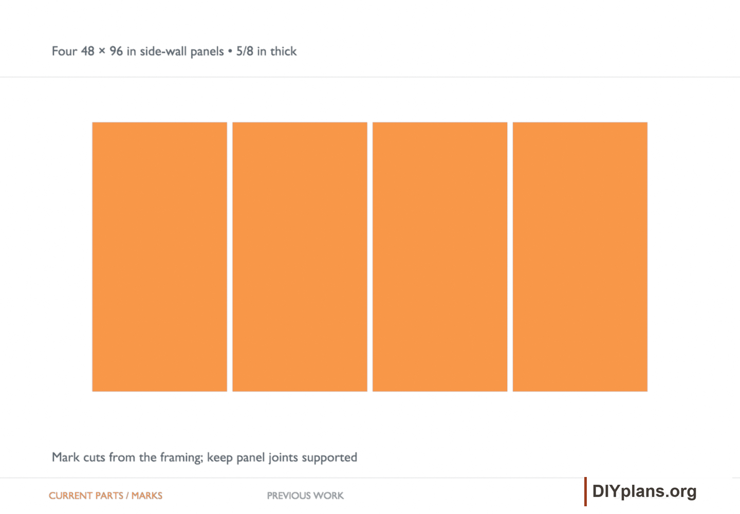
26 Mark the siding panels
- Lay out the 5/8 in T1-11 siding sheets in the wall-panel order. Mark each sheet's wall, top edge and position.
- Transfer the front doorway cuts from the framed opening. Keep both long-wall panel layouts continuous.
- Mark the separate gable pieces, eave closures and the outrigger clearances. Use the actual framing to check sloped cuts and notches.
- Keep two additional T1-11 sheets for the front door faces because the front opening cutouts cross panel joints.
- Allow the siding manufacturer's joint gaps and opening clearances. Seal cut edges as the siding instructions require.
Check: Each panel is labeled and marked for its wall, with door-face material kept aside.
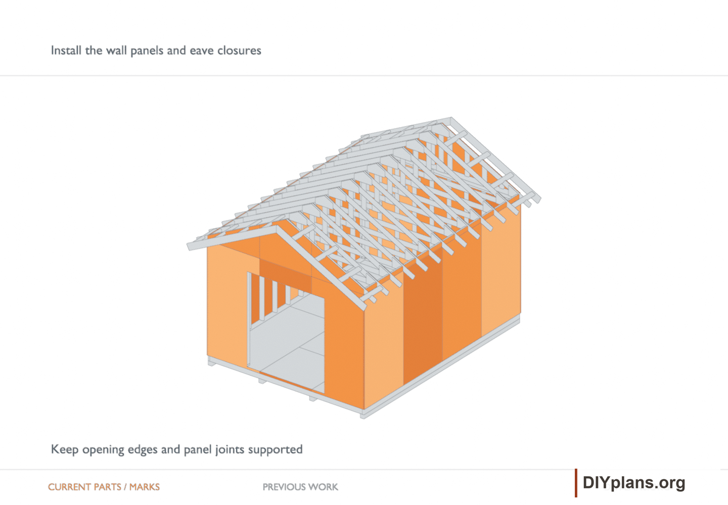
27 Install the wall siding
- Fit the required wall weather barrier and opening preparation in the order specified for the chosen siding and flashing system.
- Install the marked T1-11 wall panels, keeping their seams on the specified supports and their grooves aligned.
- Leave the required panel gaps, ground clearance and opening clearances. Use the selected siding's fastening schedule.
- Fit the separate gable panels, eave closures and corner rips. Check the outrigger clearances before fastening the gable pieces.
- Seal exposed cut edges and protect the open doorways until their units are installed.
Check: The walls and gables are clad, with supported seams and all required openings clear.
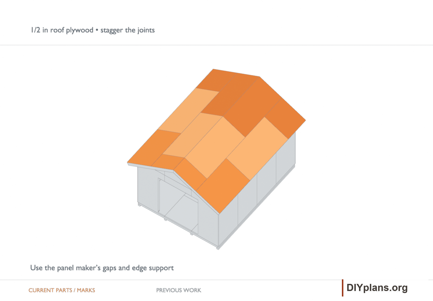
28 Lay the roof plywood
- Use 1/2 in plywood with the grade and span rating required by the roof design. Set up safe roof access and keep the required temporary bracing.
- Lay out the panels with the required strength direction across the trusses. Cut them to the staggered seam pattern and roof edges shown.
- Provide the specified support at panel joints and leave the panel manufacturer's expansion gaps.
- Fasten the sheathing to the roof design's schedule. Form any required ridge or eave ventilation openings before covering the deck.
Check: Both roof slopes are sheathed, with supported, staggered seams and the required ventilation openings.
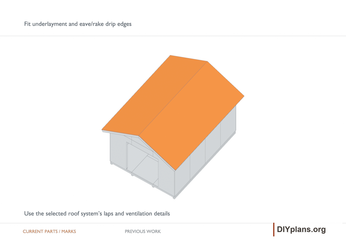
29 Fit the roof underlayment
- Confirm the roofing manufacturer's requirements for underlayment, ice-and-water protection, metal edges and ventilation before starting.
- Fit the eave drip edges and any required membrane in the specified order.
- Lay the underlayment from the eaves toward the ridge with the required side and end laps. Keep it flat and fasten it as specified.
- Fit the rake drip edges and finish the edge laps to the selected roofing details. Keep ventilation openings clear.
Check: The plywood is covered by continuous underlayment, with the metal edges and laps arranged to drain outward.
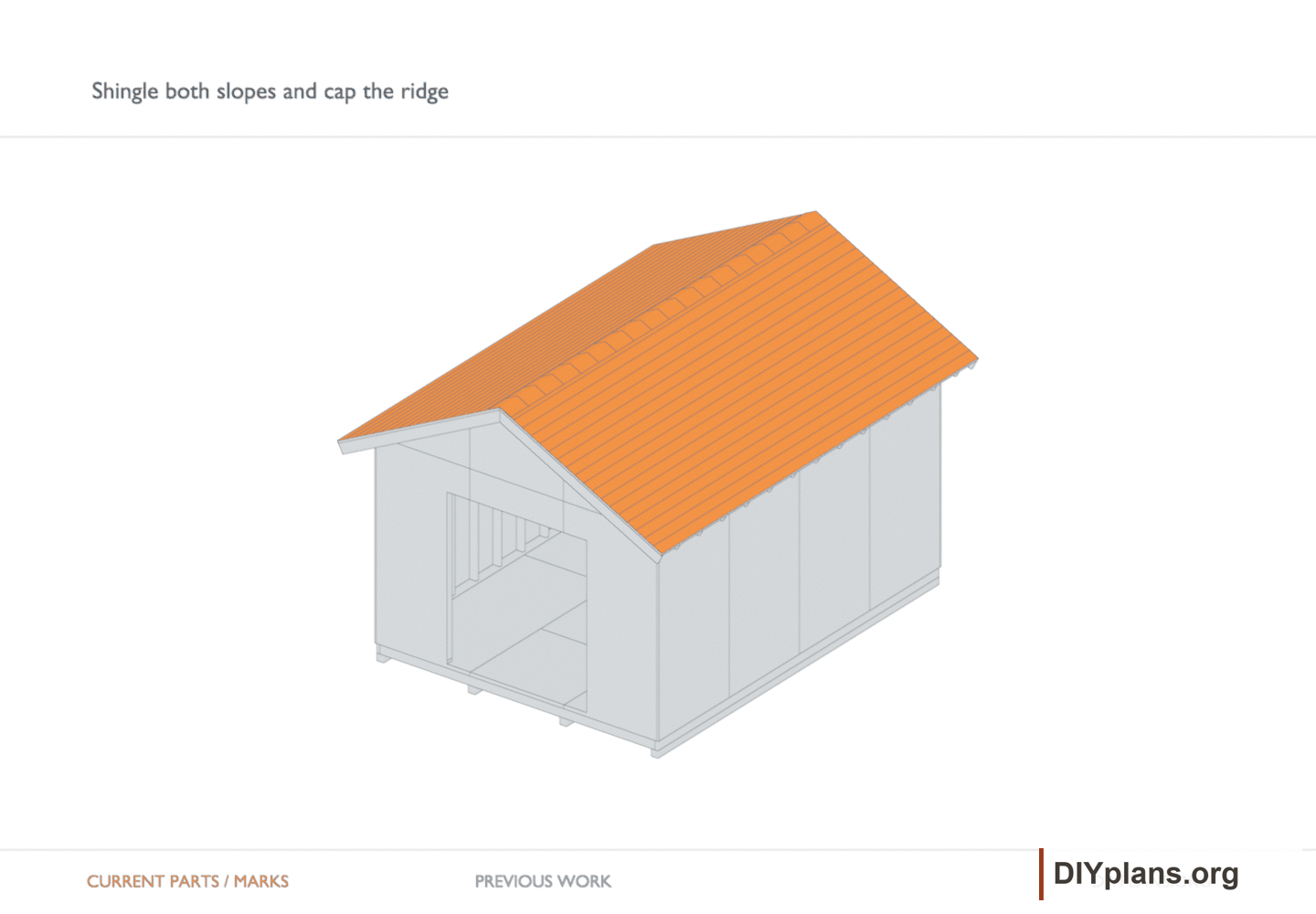
30 Shingle the roof
- Install the starter course along the required roof edges, with the specified overhang beyond the metal edge.
- Lay the shingle courses from the eaves upward. Use the manufacturer's exposure, joint offsets and fastening pattern.
- Finish both slopes at the ridge, keeping any required ventilation path open.
- Install the ridge system and ridge-cap shingles to their instructions. Check the gable edges, eaves and ridge for complete coverage.
Check: Both slopes and the ridge are weathered, with the required edge overhangs, fasteners and ventilation details complete.
31 Build the door leaves
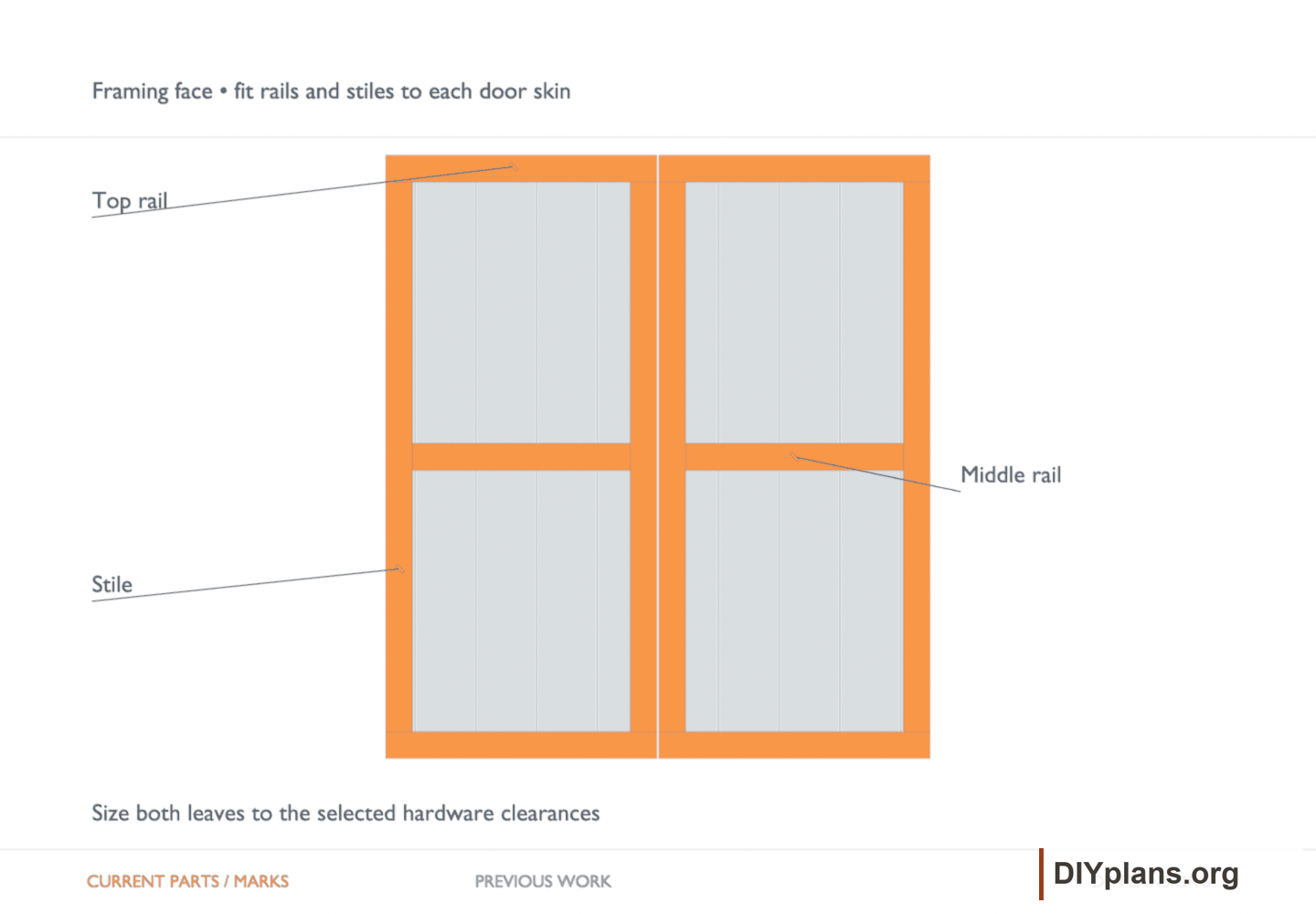
- Check that the door and hardware details suit leaves 35 3/4 in wide and 79 1/2 in high. Confirm their working gaps and threshold clearances before cutting.
- Mark and cut the two front door faces from the reserved T1-11 sheets.
- Cut each leaf's 2×4 backing frame with two 35 3/4 in top and bottom rails, two 72 1/2 in upright stiles and one 28 3/4 in middle rail.
- Assemble the frame flat and square, with the stiles between the top and bottom rails and the middle rail between the stiles. Attach the siding face with the specified fasteners.
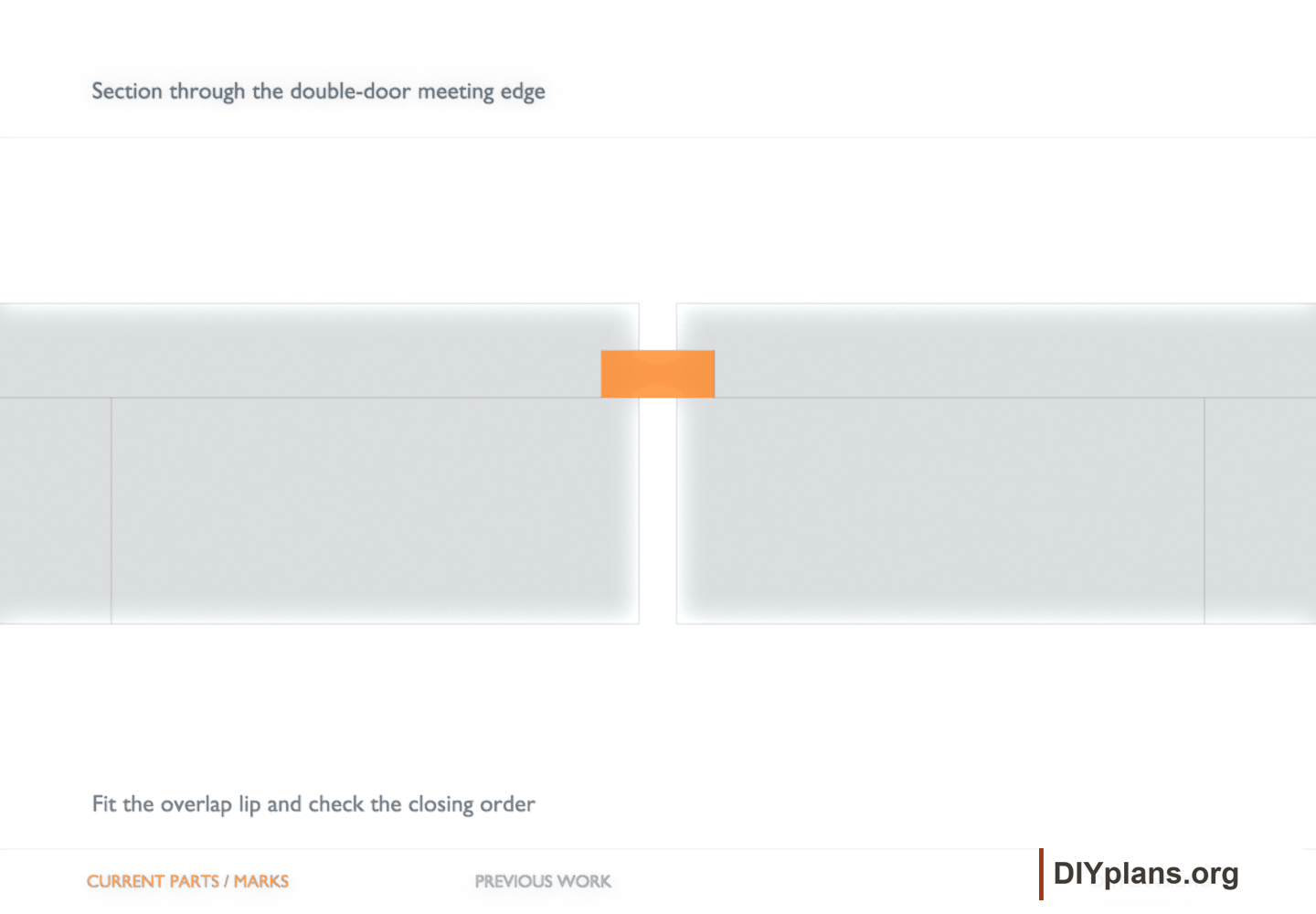
- Form the front leaves' meeting-edge rebates and fit the overlap lip to the door detail. Check which leaf must close first.
- Seal the door edges and finish faces that will be hard to reach after hanging.
Check: The door leaves are square and match their openings with the selected working clearances.
Play movementStop movement

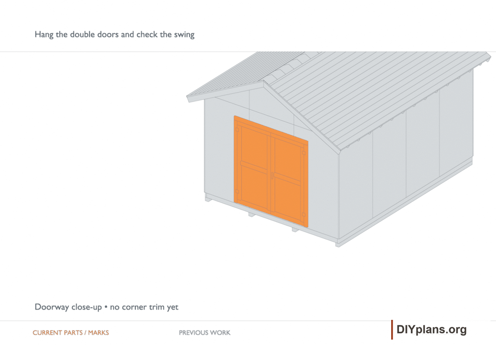
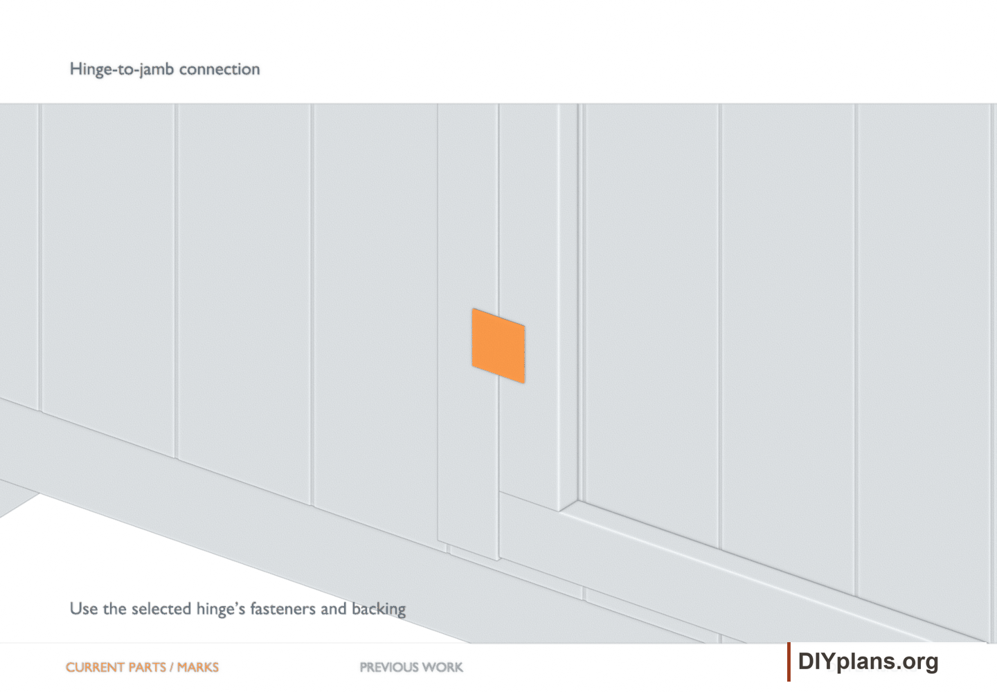
32 Hang the front doors
- Complete the front opening's jamb, head and threshold flashing and weather seals in the selected system's order.
- Fit the two 80 in outer jamb boards and the 79 in head board from 2×4 stock. Secure them to the structural framing with the specified connections.
- Dry-fit both leaves with spacers that hold the selected perimeter and meeting gaps. Check the hinge and latch backing before drilling.
- Fit the rated hinges and their specified fasteners. The layout allows four hinges across the two leaves; confirm the required number and load rating for the finished doors.
- Fit the handle, latch and required fixed-leaf restraint. Adjust the leaves so they meet evenly and swing without rubbing.
Check: Both leaves open freely, close with even gaps and latch securely without twisting the doorway.
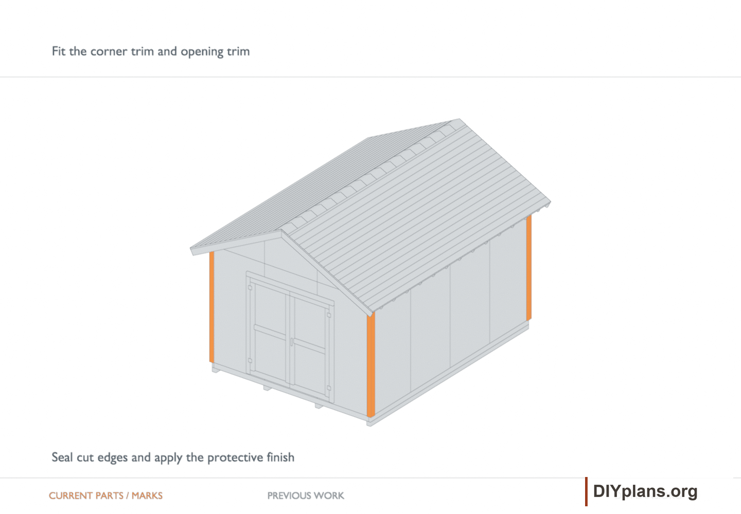
33 Fit the trim and finish
- Cut and fit the eight corner-trim pieces from nominal 1×4 stock, 3/4 in thick. Follow the corner overlap shown.
- Check the front door jamb and head boards for secure attachment and open drainage paths.
- Seal exposed cut edges and apply coatings compatible with the siding, trim and treated lumber. Follow their drying and recoating instructions.
- Check the finished corner-trim footprint at 146 3/4 × 194 3/4 in.
Check: The trim is secure and finished, and it does not obstruct door movement or drainage.
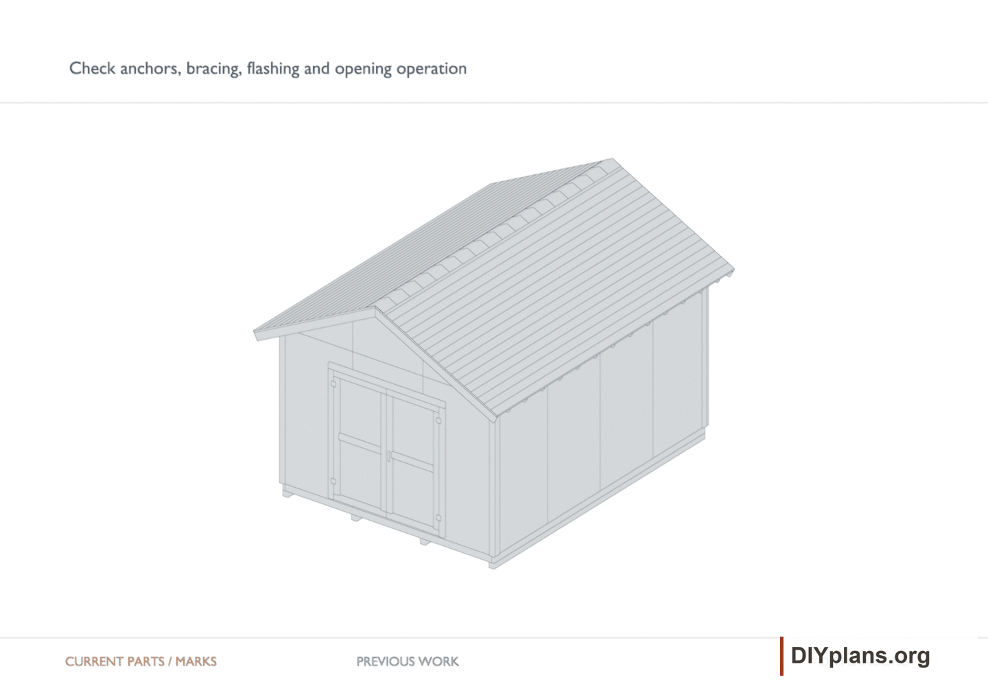
34 Check the finished shed
- Check the supports, anchors, floor level and wall plumb against the completed construction documents.
- Check the permanent wall and roof bracing, truss connections and panel fasteners. Remove temporary braces only when the permanent system is complete.
- Inspect the roof edges, ridge, wall joints and opening flashing. Confirm that water can drain away from the shed.
- Open and close every door. Check latches, seals, exposed cut edges and finish coverage.
- Complete the required local inspections before use.
Check: The required connections, water protection, opening operation and local inspections are complete.