BEFORE YOU BUILD
Use this work at your own risk
These files have not been checked for accuracy, safety, structural adequacy, or building-code compliance. They may contain serious errors and are not construction-ready. Obtain independent qualified design and review before building.
No person or organization makes any guarantee or warranty, express or implied, regarding this design, its documentation, digital files, or website views. They are not professional services and do not create an architect-client or other professional-client relationship. No promise is made about accuracy, completeness, reliability, code compliance, or fitness for your project.
Buildings and building projects are complex, and many things can go wrong. You are responsible for checking dimensions and site conditions, choosing suitable materials and methods, obtaining permits, following codes and manufacturer instructions, and getting qualified professional help when needed. To the fullest extent permitted by law, DIYPlans.org disclaims liability for damages resulting from use of this work. Read the FAQ about your responsibilities.
Instructions
Step 1 Confirm the construction details
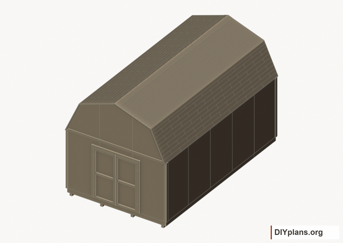
- Use the 12x20 plans and cut lists together. Mark the 144 by 240-inch footprint and the 64 by 72-inch door opening on the project drawings.
- Obtain the site foundation, anchorage, bracing and framing connection details before ordering affected materials.
- Resolve loft beam and ledger connections, roof-joint connectors and roof-spread restraint. Keep the loft for light storage with occasional access only after its permitted load and access details are established.
- Select the actual T&G floor, T1-11 siding, roofing and door hardware; use their product instructions for gaps, laps, clearances and fastening.

Check: The required site details, product instructions and fastening schedules are available.
Step 2 Lay out the footprint

- Mark a 144 by 240-inch rectangle for the outside floor edges. Label the door end front.
- Set the front-left floor corner as the datum. Measure X across the door wall, Y toward the rear and Z upward from the finished main floor.
- Compare the two diagonals and adjust until they match.
- Mark runner centerlines at X = 5 1/4, 49 3/4, 94 1/4, 138 3/4 inches. Use the foundation drawing for support pads and any supported joints.
Check: All pieces are marked with their matching cut-list IDs and reference edges.
Step 3 Prepare the foundation
- Prepare drainage and bearing pads using the approved site detail. Remove unsuitable bearing material as that detail requires.
- Level the support points along and across every runner line. Install the specified anchors while they are accessible.
- Place a support under every runner end or splice shown in the drawing. Keep the required wood-to-ground clearance.
Check: All runner bearing points are level, stable and located for the actual joints.
Step 4 Set the foundation runners
Play movementStop movement


- 2 treated foundation runner: 4x4 treated, 192 in long, actual section 3 1/2 x 3 1/2 in.
- 2 treated foundation runner: 4x4 treated, 48 in long, actual section 3 1/2 x 3 1/2 in.
- 1 treated foundation runner: 4x4 treated, 192 in long, actual section 3 1/2 x 3 1/2 in.
- 1 treated foundation runner: 4x4 treated, 48 in long, actual section 3 1/2 x 3 1/2 in.
- 1 treated foundation runner: 4x4 treated, 192 in long, actual section 3 1/2 x 3 1/2 in.
- 1 treated foundation runner: 4x4 treated, 48 in long, actual section 3 1/2 x 3 1/2 in.
- Place the runners front to rear on centerlines X = 5 1/4, 49 3/4, 94 1/4, 138 3/4 inches.
- Keep each scheduled full-length piece continuous. Where the drawing divides a runner, center its joint over the specified foundation support.
- Complete the foundation anchorage detail and recheck level.
Check: Each runner is continuously supported at the specified bearing points and anchored.
Step 5 Cut and mark the floor stock

- 1 treated side floor rim: 2x6 treated, 192 in long, actual section 1 1/2 x 5 1/2 in.
- 1 treated side floor rim: 2x6 treated, 48 in long, actual section 1 1/2 x 5 1/2 in.
- 1 treated side floor rim: 2x6 treated, 192 in long, actual section 1 1/2 x 5 1/2 in.
- 1 treated side floor rim: 2x6 treated, 48 in long, actual section 1 1/2 x 5 1/2 in.
- 1 treated floor joist: 2x6 treated, 141 in long, actual section 1 1/2 x 5 1/2 in.
- 11 treated floor joist: 2x6 treated, 141 in long, actual section 1 1/2 x 5 1/2 in.
- 1 treated floor joist: 2x6 treated, 141 in long, actual section 1 1/2 x 5 1/2 in.
- 1 treated floor joist: 2x6 treated, 141 in long, actual section 1 1/2 x 5 1/2 in.
- 2 treated floor joist: 2x6 treated, 141 in long, actual section 1 1/2 x 5 1/2 in.
- 2 loft wall bearing block: 2x6 treated, 5 1/2 in long, actual section 1 1/2 x 5 1/2 in.
- Use the matching cut list for the remaining distinct sizes.
- Mark joist centerlines at Y = 3/4, 16, 32, 48, 64, 80, 96, 112, 128, 144, 160, 176, 192, 208, 224, 239 1/4 inches from the front datum on both bare side rims.
- Mark bearing-block locations from the floor drawing. Preserve these loft reaction blocks; do not add the removed seam-only grid.
- Keep scheduled continuous pieces whole and treat cut ends according to the preservative supplier.

Check: All pieces are marked with their matching cut-list IDs and reference edges.
Step 6 Assemble the floor perimeter
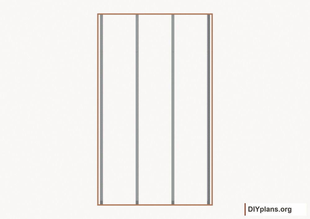
- Align the side rims along the outside floor edges and fit the front and rear joists between them.
- Keep the outside dimensions 144 by 240 inches and bring all top edges into one plane.
- Fasten the corners using the framing schedule. Keep any scheduled rim joint over its specified support.
Check: The perimeter is rectangular and every scheduled rim joint has its required bearing.
Step 7 Install the floor joists
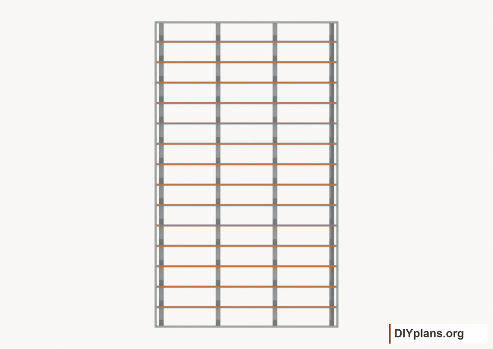
- Set the remaining joists on the marked centerlines Y = 16, 32, 48, 64, 80, 96, 112, 128, 144, 160, 176, 192, 208, 224 inches.
- Place crowns upward, align top edges with the rims and seat the joists on the runners.
- Connect joist ends and runner crossings using the selected framing and anchorage details.
Check: Every joist is seated at its runner crossings and flush with the floor perimeter.
Step 8 Install the loft bearing blocks
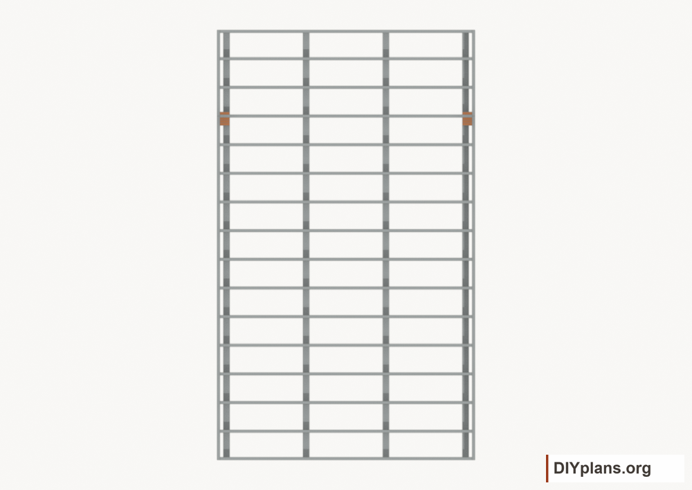
- 2 loft wall bearing block: 2x6 treated, 5 1/2 in long, actual section 1 1/2 x 5 1/2 in.
- 6 loft wall bearing block: 2x6 treated, 5 1/2 in long, actual section 1 1/2 x 5 1/2 in.
- Fit the blocks at the wall-supported loft beam reactions shown in the drawing.
- Keep block tops flush with the joists and complete their specified attachment before covering the floor.

Check: The wall reactions have a continuous path through the retained floor blocking to the outer runner lines.
Step 9 Square and anchor the floor
- Compare the floor diagonals, correct the rectangle and recheck level.
- Complete all floor-to-runner and runner-to-foundation connections before decking conceals them.
- Check for gaps at bearing contacts and correct them using the foundation detail.
Check: The frame is square, level and connected.
Step 10 Plan the T&G floor panels


- Prepare the 9 floor panels using the exact sheet allocation and factory-edge schedule.
- Check the selected product against the modeled 23/32-inch thickness and required usable face width.
- Run the panel strength direction front to rear, perpendicular to the floor joists. Retain each specified factory tongue and groove.
- Mark short-end cuts from the supported joint positions. Do not substitute square edges at unsupported long joints.

Check: All pieces are marked with their matching cut-list IDs and reference edges.
Step 11 Lay floor strip 1
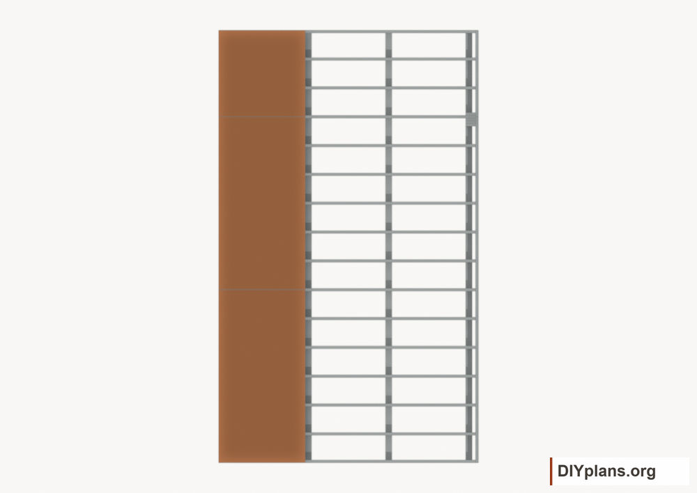
- Start this strip at X = 0 inches from the left floor datum.
- 2 t&g floor panel: 23/32 T&G plywood, full face, 95 7/8 in long, actual section 23/32 x 48 in.
- 1 t&g floor panel: 23/32 T&G plywood, full face, 47 7/8 in long, actual section 23/32 x 48 in.
- Set the panels in the positions shown; engage the retained factory profiles without forcing them.
- Maintain the selected product gaps, support the short-end joints on joists and fasten using its panel schedule.
Check: The strip lies flat; its specified factory edges and short-end supports remain intact.
Step 12 Lay floor strip 2
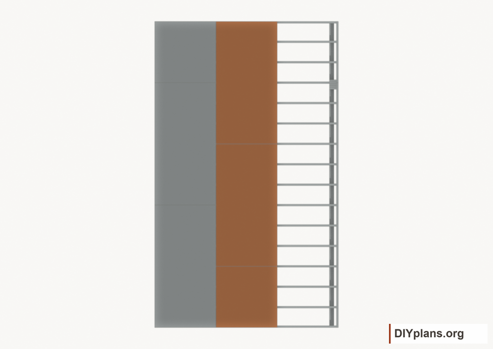
- Start this strip at X = 48 1/8 inches from the left floor datum.
- 1 t&g floor panel: 23/32 T&G plywood, full face, 47 7/8 in long, actual section 23/32 x 48 in.
- 2 t&g floor panel: 23/32 T&G plywood, full face, 95 7/8 in long, actual section 23/32 x 48 in.
- Set the panels in the positions shown; engage the retained factory profiles without forcing them.
- Maintain the selected product gaps, support the short-end joints on joists and fasten using its panel schedule.
Check: The strip lies flat; its specified factory edges and short-end supports remain intact.
Step 13 Lay floor strip 3
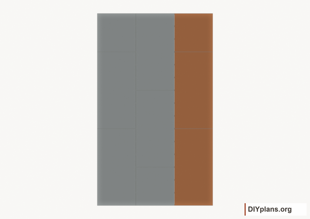
- Start this strip at X = 96 1/4 inches from the left floor datum.
- 2 t&g floor panel: 23/32 T&G plywood, full face, 95 7/8 in long, actual section 23/32 x 47 3/4 in.
- 1 t&g floor panel: 23/32 T&G plywood, full face, 47 7/8 in long, actual section 23/32 x 47 3/4 in.
- Set the panels in the positions shown; engage the retained factory profiles without forcing them.
- Maintain the selected product gaps, support the short-end joints on joists and fasten using its panel schedule.
Check: The strip lies flat; its specified factory edges and short-end supports remain intact.
Step 14 Cut and mark the left wall


- 1 left wall stud: 2x4, 79 1/2 in long, actual section 1 1/2 x 3 1/2 in.
- 1 left wall corner backing stud: 2x4, 79 1/2 in long, actual section 1 1/2 x 3 1/2 in.
- 11 left wall stud: 2x4, 79 1/2 in long, actual section 1 1/2 x 3 1/2 in.
- 1 left wall stud: 2x4, 79 1/2 in long, actual section 1 1/2 x 3 1/2 in.
- 1 left wall stud: 2x4, 79 1/2 in long, actual section 1 1/2 x 3 1/2 in.
- 1 left wall stud: 2x4, 79 1/2 in long, actual section 1 1/2 x 3 1/2 in.
- 1 left wall corner backing stud: 2x4, 79 1/2 in long, actual section 1 1/2 x 3 1/2 in.
- 1 left wall bottom plate: 2x4, 192 in long, actual section 1 1/2 x 3 1/2 in.
- 1 left wall bottom plate: 2x4, 48 in long, actual section 1 1/2 x 3 1/2 in.
- 1 left wall first top plate: 2x4, 192 in long, actual section 1 1/2 x 3 1/2 in.
- Use the matching cut list for the remaining distinct sizes.
- Lay the matching first-layer plates side by side and transfer the member stations from the wall drawing.
- Mark both stud edges and label opening, corner-backing and loft-seat members before fastening.
- Keep second top plates aside until all four walls are standing.

Check: All pieces are marked with their matching cut-list IDs and reference edges.
Step 15 Assemble and raise the left wall
Play movementStop movement

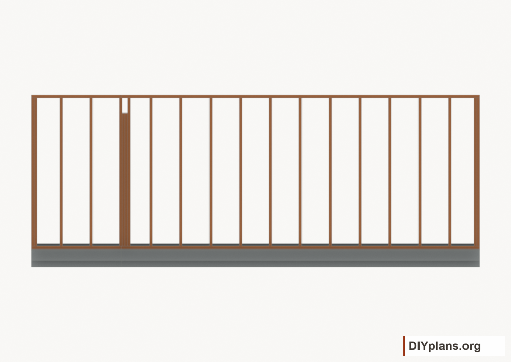
- Assemble the labeled plates and studs flat on a supported work surface; align the reference edges and square the frame.
- Fit the corner backing and any wall-contained loft king and jack studs at their drawing positions. Keep the beam pockets open above the jacks.
- Fasten using the wall connection schedule, then use the planned lifting method and enough helpers to raise the wall.
- Plumb, anchor and temporarily brace the wall before releasing it.
Check: The left wall is plumb, anchored and braced; its opening and support pockets match the drawing.
Step 16 Cut and mark the right wall


- 1 right wall stud: 2x4, 79 1/2 in long, actual section 1 1/2 x 3 1/2 in.
- 1 right wall corner backing stud: 2x4, 79 1/2 in long, actual section 1 1/2 x 3 1/2 in.
- 11 right wall stud: 2x4, 79 1/2 in long, actual section 1 1/2 x 3 1/2 in.
- 1 right wall stud: 2x4, 79 1/2 in long, actual section 1 1/2 x 3 1/2 in.
- 1 right wall stud: 2x4, 79 1/2 in long, actual section 1 1/2 x 3 1/2 in.
- 1 right wall stud: 2x4, 79 1/2 in long, actual section 1 1/2 x 3 1/2 in.
- 1 right wall corner backing stud: 2x4, 79 1/2 in long, actual section 1 1/2 x 3 1/2 in.
- 1 right wall bottom plate: 2x4, 192 in long, actual section 1 1/2 x 3 1/2 in.
- 1 right wall bottom plate: 2x4, 48 in long, actual section 1 1/2 x 3 1/2 in.
- 1 right wall first top plate: 2x4, 192 in long, actual section 1 1/2 x 3 1/2 in.
- Use the matching cut list for the remaining distinct sizes.
- Lay the matching first-layer plates side by side and transfer the member stations from the wall drawing.
- Mark both stud edges and label opening, corner-backing and loft-seat members before fastening.
- Keep second top plates aside until all four walls are standing.

Check: All pieces are marked with their matching cut-list IDs and reference edges.
Step 17 Assemble and raise the right wall
Play movementStop movement

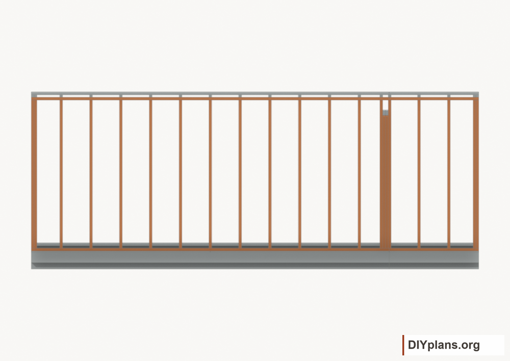
- Assemble the labeled plates and studs flat on a supported work surface; align the reference edges and square the frame.
- Fit the corner backing and any wall-contained loft king and jack studs at their drawing positions. Keep the beam pockets open above the jacks.
- Fasten using the wall connection schedule, then use the planned lifting method and enough helpers to raise the wall.
- Plumb, anchor and temporarily brace the wall before releasing it.
Check: The right wall is plumb, anchored and braced; its opening and support pockets match the drawing.
Step 18 Cut and mark the rear wall

- 1 rear wall bottom plate: 2x4, 137 in long, actual section 1 1/2 x 3 1/2 in.
- 1 rear wall first top plate: 2x4, 137 in long, actual section 1 1/2 x 3 1/2 in.
- 8 rear wall stud: 2x4, 79 1/2 in long, actual section 1 1/2 x 3 1/2 in.
- 1 rear wall stud: 2x4, 79 1/2 in long, actual section 1 1/2 x 3 1/2 in.
- 1 rear wall stud: 2x4, 79 1/2 in long, actual section 1 1/2 x 3 1/2 in.
- Lay the matching first-layer plates side by side and transfer the member stations from the wall drawing.
- Mark both stud edges and label opening, corner-backing and loft-seat members before fastening.
- Keep second top plates aside until all four walls are standing.

Check: All pieces are marked with their matching cut-list IDs and reference edges.
Step 19 Assemble and raise the rear wall
Play movementStop movement

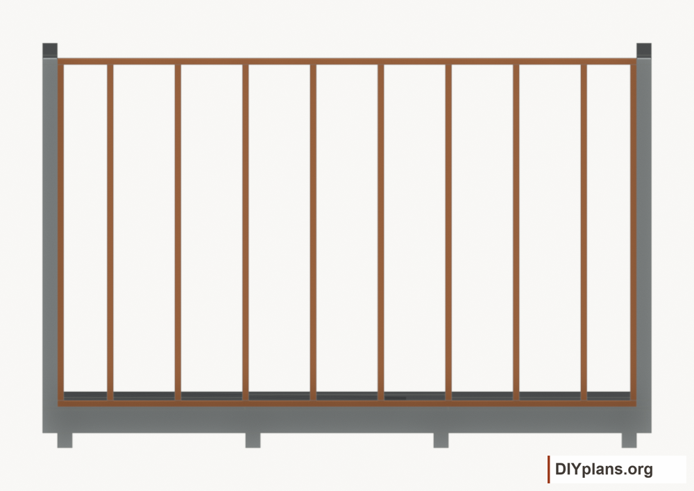
- Assemble the labeled plates and studs flat on a supported work surface; align the reference edges and square the frame.
- Fit the corner backing and any wall-contained loft king and jack studs at their drawing positions. Keep the beam pockets open above the jacks.
- Fasten using the wall connection schedule, then use the planned lifting method and enough helpers to raise the wall.
- Plumb, anchor and temporarily brace the wall before releasing it.
Check: The rear wall is plumb, anchored and braced; its opening and support pockets match the drawing.
Step 20 Cut and mark the front wall


- 2 front wall bottom plate: 2x4, 36 1/2 in long, actual section 1 1/2 x 3 1/2 in.
- 1 front wall first top plate: 2x4, 137 in long, actual section 1 1/2 x 3 1/2 in.
- 7 front wall king or full stud: 2x4, 79 1/2 in long, actual section 1 1/2 x 3 1/2 in.
- 1 front wall king or full stud: 2x4, 79 1/2 in long, actual section 1 1/2 x 3 1/2 in.
- 2 door header jack stud: 2x4, 70 1/2 in long, actual section 1 1/2 x 3 1/2 in.
- 1 door header ply: 2x6, 67 in long, actual section 1 1/2 x 5 1/2 in.
- 1 door header ply: 2x6, 67 in long, actual section 1 1/2 x 5 1/2 in.
- 1 door header spacer: 1/2 plywood, 67 in long, actual section 1/2 x 5 1/2 in.
- 5 door header cripple: 2x4, 3 1/2 in long, actual section 1 1/2 x 3 1/2 in.
- 1 door header cripple: 2x4, 3 1/2 in long, actual section 1 1/2 x 3 1/2 in.
- Lay the matching first-layer plates side by side and transfer the member stations from the wall drawing.
- Mark both stud edges and label opening, corner-backing and loft-seat members before fastening.
- Keep second top plates aside until all four walls are standing.

Check: All pieces are marked with their matching cut-list IDs and reference edges.
Step 21 Assemble and raise the front wall
Play movementStop movement

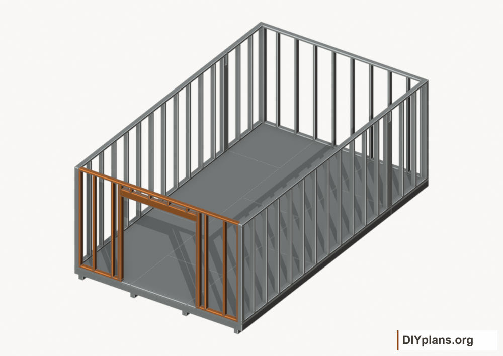
- Frame the 64 by 72-inch clear opening with the labeled king studs, jacks, header plies, spacer and cripples.
- Measure the opening height from the finished floor datum. Keep the header underside at the drawing elevation.
- Assemble and square the front wall on a supported platform; fasten according to the selected header and wall connection details.
- Lift the wall into place, align it between the side walls and plumb, anchor and brace it.
Check: The front wall is plumb, anchored and braced; its opening and support pockets match the drawing.
Step 22 Lap the wall cap plates
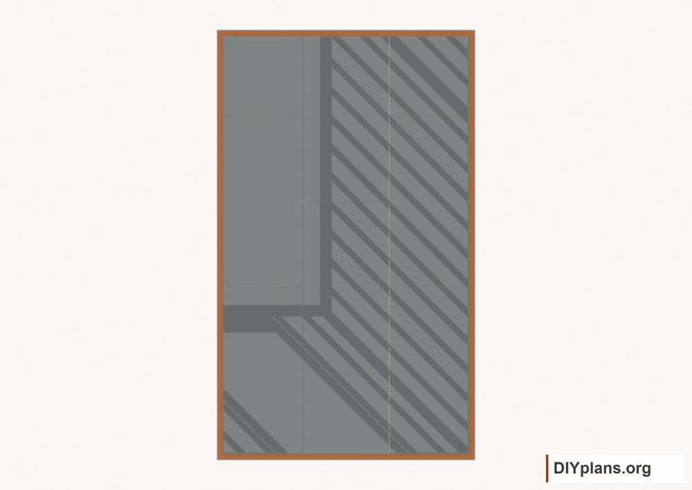
- 1 left wall cap plate: 2x4, 156 1/2 in long, actual section 1 1/2 x 3 1/2 in.
- 1 left wall cap plate: 2x4, 76 1/2 in long, actual section 1 1/2 x 3 1/2 in.
- 1 right wall cap plate: 2x4, 156 1/2 in long, actual section 1 1/2 x 3 1/2 in.
- 1 right wall cap plate: 2x4, 76 1/2 in long, actual section 1 1/2 x 3 1/2 in.
- 1 rear wall cap plate: 2x4, 144 in long, actual section 1 1/2 x 3 1/2 in.
- 1 front wall cap plate: 2x4, 144 in long, actual section 1 1/2 x 3 1/2 in.
- Fit the second top plates over the standing walls using the marked corner laps and staggered joint positions.
- Bring the completed cap surface to Z = 84 inches above the floor.
- Complete the specified wall-to-wall ties and recheck the wall diagonals, plumb and temporary bracing.

Check: Caps tie the walls together with the drawn corner laps and joint offsets.
Step 23 Cut and mark the loft framing

- 1 flush loft beam ply: 2x8, 144 in long, actual section 1 1/2 x 7 1/4 in.
- 1 flush loft beam ply: 2x8, 144 in long, actual section 1 1/2 x 7 1/4 in.
- 1 loft rear ledger: 2x6, 137 in long, actual section 1 1/2 x 5 1/2 in.
- 8 loft joist: 2x6, 44 7/8 in long, actual section 1 1/2 x 5 1/2 in.
- 1 loft joist: 2x6, 44 7/8 in long, actual section 1 1/2 x 5 1/2 in.
- 1 loft joist: 2x6, 44 7/8 in long, actual section 1 1/2 x 5 1/2 in.
- Mark the beam-end bearing, rear ledger and joist stations from the loft drawing.
- Select the joist hangers, beam-ply fastening and ledger anchors before cutting connection-dependent details.

Check: All pieces are marked with their matching cut-list IDs and reference edges.
Step 24 Seat the wall-supported loft beam
Play movementStop movement

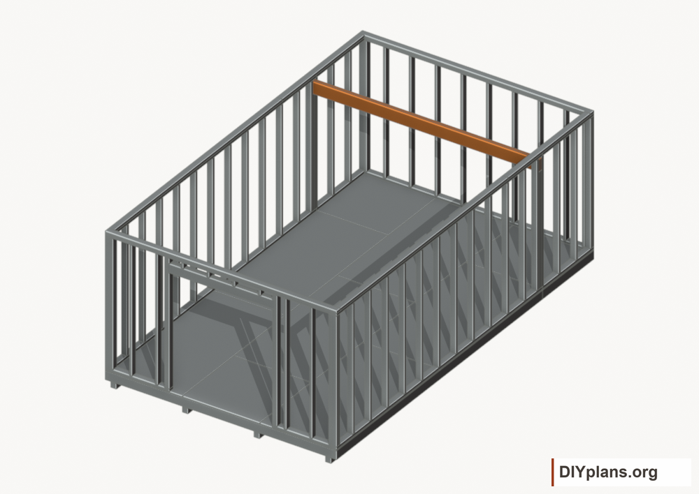
- Assemble the continuous beam plies using the selected ply-fastening detail.
- Lower the beam onto the paired wall seats with the planned lifting method; keep both ends fully seated.
- Complete beam-end and wall-support connections. Keep the main floor free of interior posts.
Check: Both beam ends bear at the drawn wall seats and are restrained by the selected connections.
Step 25 Attach the rear loft ledger

- 1 loft rear ledger: 2x6, 137 in long, actual section 1 1/2 x 5 1/2 in.
- Set the ledger at its drawing height against the rear-wall studs.
- Install the selected structural anchors into the required backing; verify edge distances and bearing.
Check: The ledger is level and attached using its specified structural connection.
Step 26 Install the loft joists
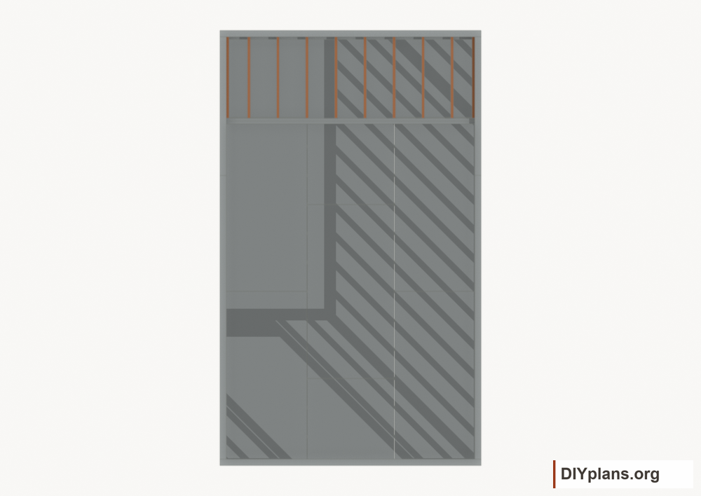
- Mark joist centerlines at X = 4 1/4, 16, 32, 48, 64, 80, 96, 112, 128, 139 3/4 inches.
- 8 loft joist: 2x6, 44 7/8 in long, actual section 1 1/2 x 5 1/2 in.
- 1 loft joist: 2x6, 44 7/8 in long, actual section 1 1/2 x 5 1/2 in.
- 1 loft joist: 2x6, 44 7/8 in long, actual section 1 1/2 x 5 1/2 in.
- Fit each front end in its selected hanger and retain the drawn rear bearing on the ledger.
- Use the connector manufacturer’s fasteners; do not substitute general-purpose screws.
Check: Every loft joist has the specified front connector and rear bearing.
Step 27 Cut the loft panels

- 1 loft deck panel: 3/4 plywood, 92 7/16 in long, actual section 3/4 x 48 in.
- 1 loft deck panel: 3/4 plywood, 44 7/16 in long, actual section 3/4 x 48 in.
- Mark the supported panel joints from the loft drawing and follow the sheet allocation.
- Keep the specified strength direction and panel gaps.
Check: All pieces are marked with their matching cut-list IDs and reference edges.
Step 28 Fasten the loft deck
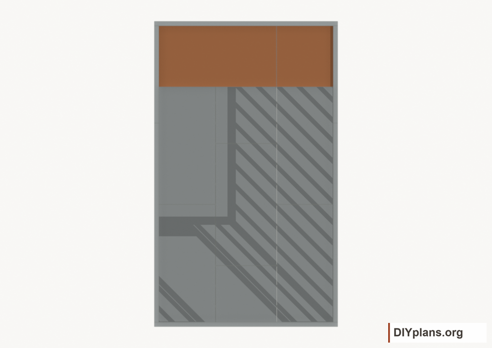
- Fit the loft panels with their short joints supported as drawn.
- Fasten using the selected panel schedule and inspect the edge support.
- Keep the loft unloaded until its permitted load, access and edge-protection details are complete.
Check: The deck is supported and fastened, with unresolved access and loading requirements recorded.
Step 29 Cut and label the roof profiles

- 11 left lower rafter: 2x4, 47 3/4 in long, actual section 1 1/2 x 3 1/2 in.
- 11 left upper rafter: 2x4, 54 13/16 in long, actual section 1 1/2 x 3 1/2 in.
- 11 right lower rafter: 2x4, 47 3/4 in long, actual section 1 1/2 x 3 1/2 in.
- 11 right upper rafter: 2x4, 54 13/16 in long, actual section 1 1/2 x 3 1/2 in.
- Transfer the exact stock-coordinate profiles to the marked blanks; keep mirrored parts labeled.
- Cut one complete gambrel frame first and dry-fit it against the roof layout before repeating the cuts.
- Use an engineered roof-joint connection design. The plates shown indicate their positions, not a product specification.

Check: All pieces are marked with their matching cut-list IDs and reference edges.
Step 30 Raise the front end roof frame
Play movementStop movement

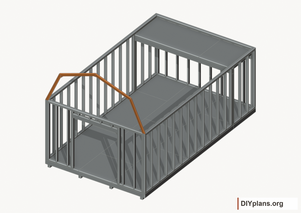
- Assemble the four labeled members on a flat layout using the specified roof connectors and fastening process.
- Lift the completed frame onto the caps at centerline Y = 3/4 inches. Preserve its left/right orientation.
- Hold the frame plumb and complete the designed bearing, uplift and spread-restraint connections.
- Brace the frame before releasing the lifting support and keep prior frames restrained.

Check: The frame is seated, plumb, connected and temporarily braced.
Step 31 Raise the rear end roof frame
Play movementStop movement

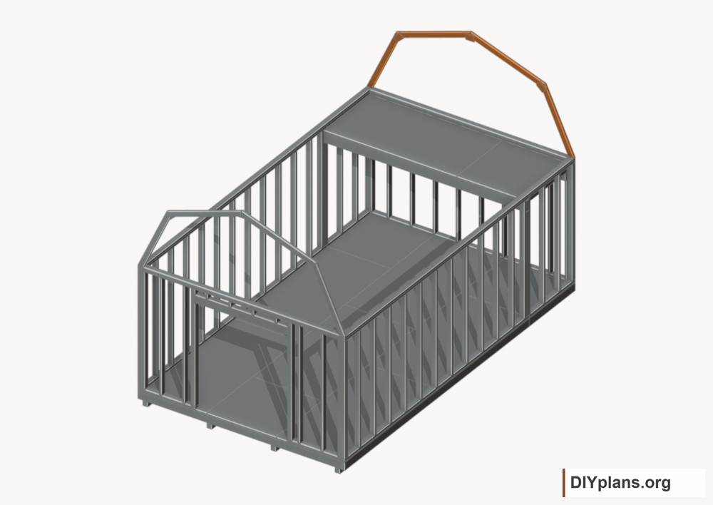
- Assemble the four labeled members on a flat layout using the specified roof connectors and fastening process.
- Lift the completed frame onto the caps at centerline Y = 239 1/4 inches. Preserve its left/right orientation.
- Hold the frame plumb and complete the designed bearing, uplift and spread-restraint connections.
- Brace the frame before releasing the lifting support and keep prior frames restrained.
Check: The frame is seated, plumb, connected and temporarily braced.
Step 32 Raise the intermediate 1 roof frame
Play movementStop movement

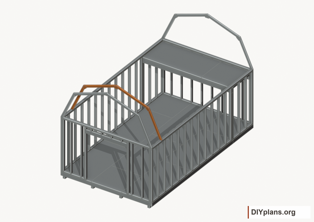
- Assemble the four labeled members on a flat layout using the specified roof connectors and fastening process.
- Lift the completed frame onto the caps at centerline Y = 24 inches. Preserve its left/right orientation.
- Hold the frame plumb and complete the designed bearing, uplift and spread-restraint connections.
- Brace the frame before releasing the lifting support and keep prior frames restrained.
Check: The frame is seated, plumb, connected and temporarily braced.
Step 33 Raise the intermediate 2 roof frame
Play movementStop movement

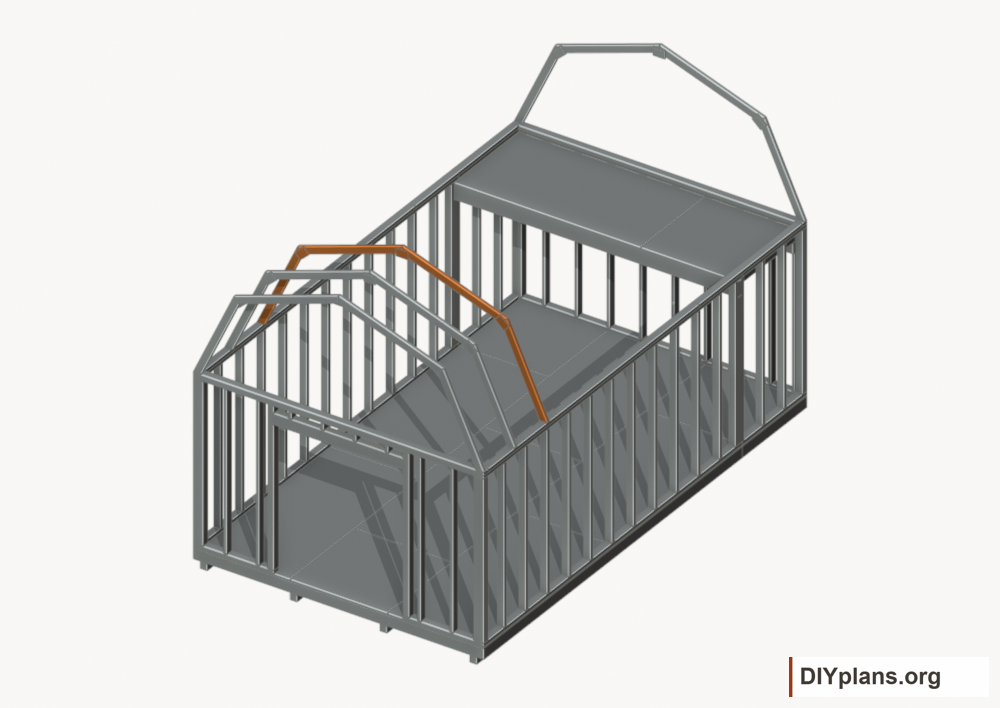
- Assemble the four labeled members on a flat layout using the specified roof connectors and fastening process.
- Lift the completed frame onto the caps at centerline Y = 48 inches. Preserve its left/right orientation.
- Hold the frame plumb and complete the designed bearing, uplift and spread-restraint connections.
- Brace the frame before releasing the lifting support and keep prior frames restrained.
Check: The frame is seated, plumb, connected and temporarily braced.
Step 34 Raise the intermediate 3 roof frame
Play movementStop movement

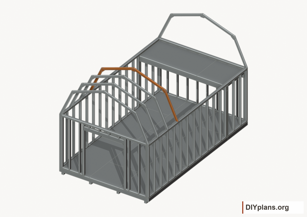
- Assemble the four labeled members on a flat layout using the specified roof connectors and fastening process.
- Lift the completed frame onto the caps at centerline Y = 72 inches. Preserve its left/right orientation.
- Hold the frame plumb and complete the designed bearing, uplift and spread-restraint connections.
- Brace the frame before releasing the lifting support and keep prior frames restrained.
Check: The frame is seated, plumb, connected and temporarily braced.
Step 35 Raise the intermediate 4 roof frame
Play movementStop movement

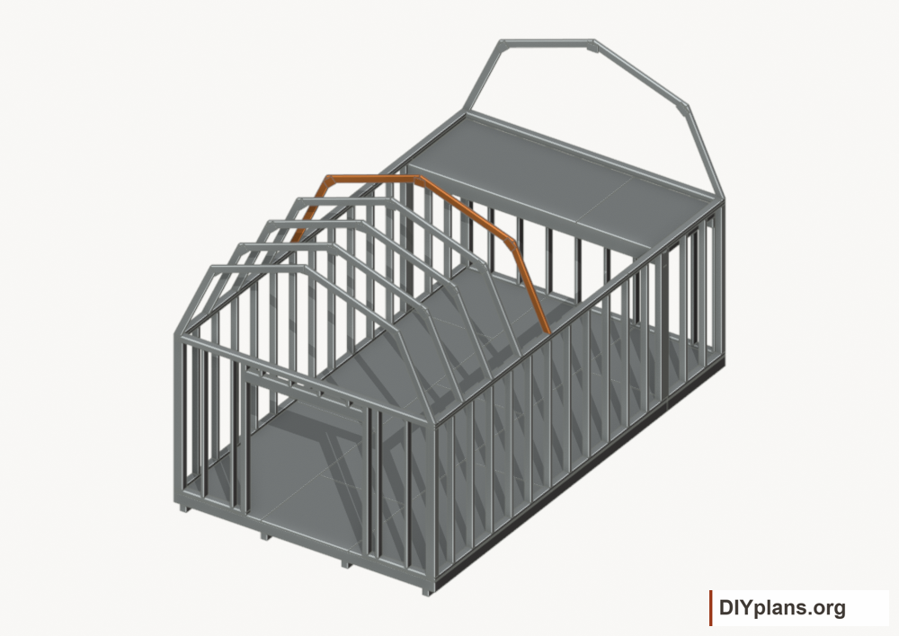
- Assemble the four labeled members on a flat layout using the specified roof connectors and fastening process.
- Lift the completed frame onto the caps at centerline Y = 96 inches. Preserve its left/right orientation.
- Hold the frame plumb and complete the designed bearing, uplift and spread-restraint connections.
- Brace the frame before releasing the lifting support and keep prior frames restrained.
Check: The frame is seated, plumb, connected and temporarily braced.
Step 36 Raise the intermediate 5 roof frame
Play movementStop movement

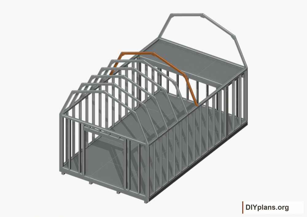
- Assemble the four labeled members on a flat layout using the specified roof connectors and fastening process.
- Lift the completed frame onto the caps at centerline Y = 120 inches. Preserve its left/right orientation.
- Hold the frame plumb and complete the designed bearing, uplift and spread-restraint connections.
- Brace the frame before releasing the lifting support and keep prior frames restrained.
Check: The frame is seated, plumb, connected and temporarily braced.
Step 37 Raise the intermediate 6 roof frame
Play movementStop movement

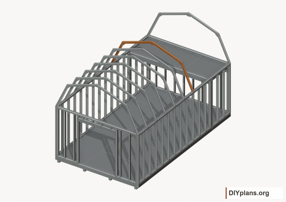
- Assemble the four labeled members on a flat layout using the specified roof connectors and fastening process.
- Lift the completed frame onto the caps at centerline Y = 144 inches. Preserve its left/right orientation.
- Hold the frame plumb and complete the designed bearing, uplift and spread-restraint connections.
- Brace the frame before releasing the lifting support and keep prior frames restrained.
Check: The frame is seated, plumb, connected and temporarily braced.
Step 38 Raise the intermediate 7 roof frame
Play movementStop movement

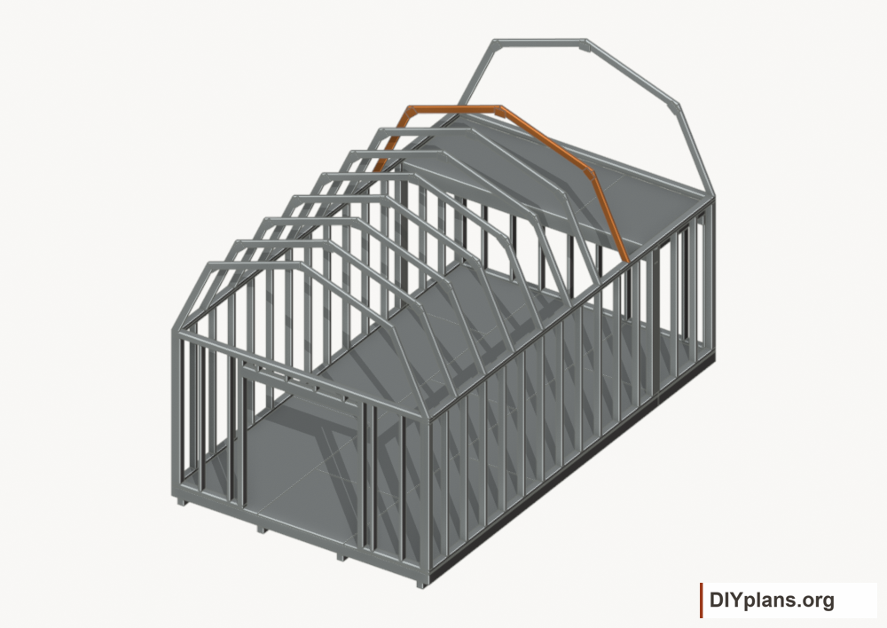
- Assemble the four labeled members on a flat layout using the specified roof connectors and fastening process.
- Lift the completed frame onto the caps at centerline Y = 168 inches. Preserve its left/right orientation.
- Hold the frame plumb and complete the designed bearing, uplift and spread-restraint connections.
- Brace the frame before releasing the lifting support and keep prior frames restrained.
Check: The frame is seated, plumb, connected and temporarily braced.
Step 39 Raise the intermediate 8 roof frame
Play movementStop movement

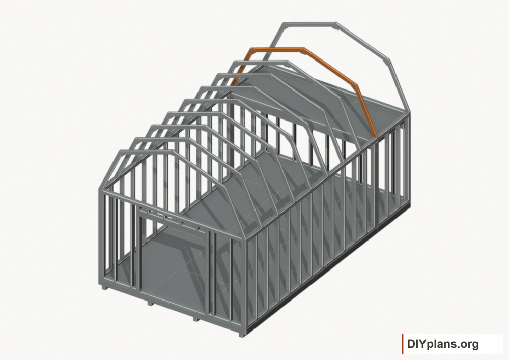
- Assemble the four labeled members on a flat layout using the specified roof connectors and fastening process.
- Lift the completed frame onto the caps at centerline Y = 192 inches. Preserve its left/right orientation.
- Hold the frame plumb and complete the designed bearing, uplift and spread-restraint connections.
- Brace the frame before releasing the lifting support and keep prior frames restrained.
Check: The frame is seated, plumb, connected and temporarily braced.
Step 40 Raise the intermediate 9 roof frame
Play movementStop movement

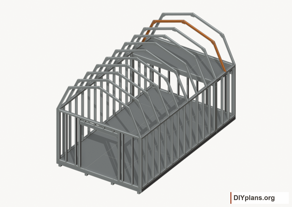
- Assemble the four labeled members on a flat layout using the specified roof connectors and fastening process.
- Lift the completed frame onto the caps at centerline Y = 216 inches. Preserve its left/right orientation.
- Hold the frame plumb and complete the designed bearing, uplift and spread-restraint connections.
- Brace the frame before releasing the lifting support and keep prior frames restrained.
Check: The frame is seated, plumb, connected and temporarily braced.
Step 41 Cut the gable infill and spacers


- Transfer the exact gable-stud and relieved-spacer profiles from the cut-profile drawings.
- Keep the gable studs perpendicular to the end wall, with their full wall depth front to rear.
- Label front and rear spacers and inner rafters; keep their connector reliefs correctly oriented.

Check: All pieces are marked with their matching cut-list IDs and reference edges.
Step 42 Fit the perpendicular gable infill
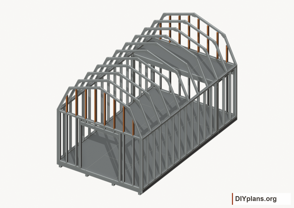
- Fit the 16 shaped infill members at the front and rear positions shown.
- Seat their lower ends on the wall caps and fit the angled tops to the drawn roof boundary.
- Keep their full wall depth perpendicular to the end face and fasten with the selected end-wall detail.

Check: The infill follows the roof outline and preserves the full end-wall depth.
Step 43 Fit the relieved end-frame spacers
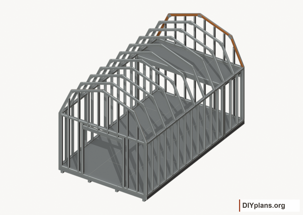
- Place the shaped plywood spacers against the inside of the outer end rafters.
- Align each relief with the connector location and preserve the specified cavity.
- Fasten with the selected paired-frame detail; do not fill connector clearances with unshown packing.
Check: Every spacer is oriented correctly and the connector reliefs remain open.
Step 44 Fit the inner end rafters
Play movementStop movement

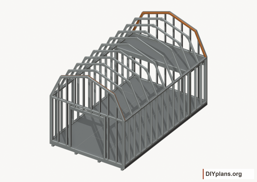
- Fit the additional inner rafters against the spacer faces, matching each labeled profile.
- Keep the inner faces aligned with the end-wall lining plane.
- Complete the selected frame-to-spacer connection. Choose insulation, lining and moisture control separately.
Check: The paired end assemblies finish flush to their intended inner lining plane.
Step 45 Cut the roof panel seam blocking


- 4 roof panel seam blocking: 2x4, 19 3/4 in long, actual section 1 1/2 x 3 1/2 in.
- 16 roof panel seam blocking: 2x4, 22 1/2 in long, actual section 1 1/2 x 3 1/2 in.
- Mark each length and slope position from the measured blocking drawing before cutting.
- Keep the top support faces aligned with the roof-panel seam and label front, intermediate and rear pieces.

Check: All pieces are marked with their matching cut-list IDs and reference edges.
Step 46 Fit the roof panel seam blocking
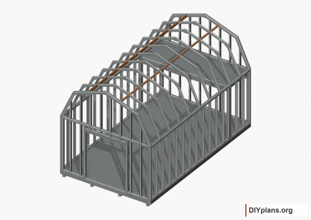
- Fit the labeled longitudinal blocks between the completed roof frames, using the inner end rafters at the front and rear.
- Set their support faces flush with the roof plane beneath the panel seams.
- Complete the selected block-end connections before installing roof sheathing.
Check: The seams have continuous support between adjacent rafters without displaced or floating blocks.
Step 47 Lay out the T1-11 siding cuts


- Verify the delivered panel-body thickness and usable factory-lap coverage before cutting.
- Keep all grooves vertical. Cut square wall blanks from the sheet allocation and transfer shaped gable and door-opening profiles exactly.
- Seal cut edges as the panel manufacturer requires. Keep openings, laps and the wall-to-gable joint labeled.


Check: All pieces are marked with their matching cut-list IDs and reference edges.
Step 48 Prepare the wall weather details
- Install the selected weather barrier and opening flashings in their required lap order.
- Mark fastening lines over the framing and preserve the specified drainage paths.
- Prepare the horizontal wall-to-gable seam flashing before trim conceals the joint.
Check: The selected wall assembly can drain outward around openings and horizontal joints.
Step 49 Fasten the left wall siding
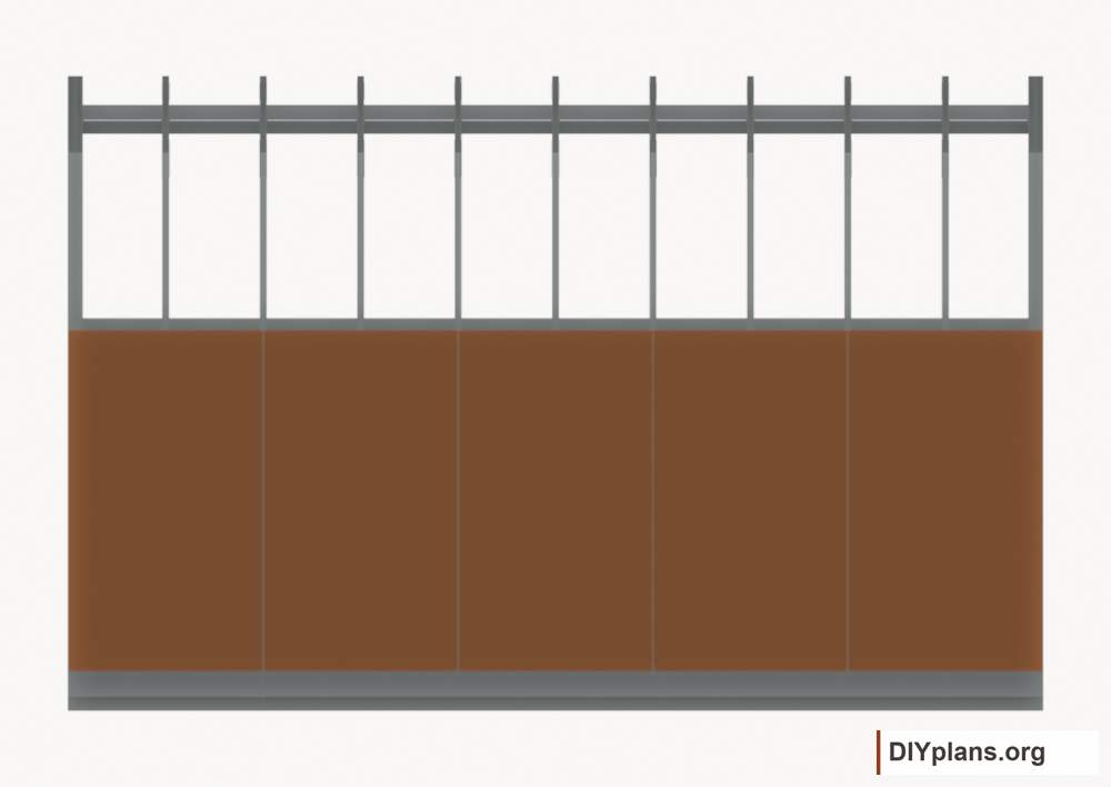
- Start from the drawing datum and align the marked factory edges and opening cuts.
- Maintain the selected product edge clearances, panel gaps and vertical groove direction.
- Fasten into the marked framing with the selected panel schedule; keep drainage and flashing laps open.

Check: Panel joints have their required backing and clearances; opening cuts match the frame.
Step 50 Fasten the right wall siding
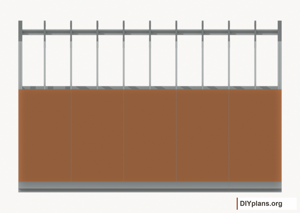
- Start from the drawing datum and align the marked factory edges and opening cuts.
- Maintain the selected product edge clearances, panel gaps and vertical groove direction.
- Fasten into the marked framing with the selected panel schedule; keep drainage and flashing laps open.

Check: Panel joints have their required backing and clearances; opening cuts match the frame.
Step 51 Fasten the rear wall siding
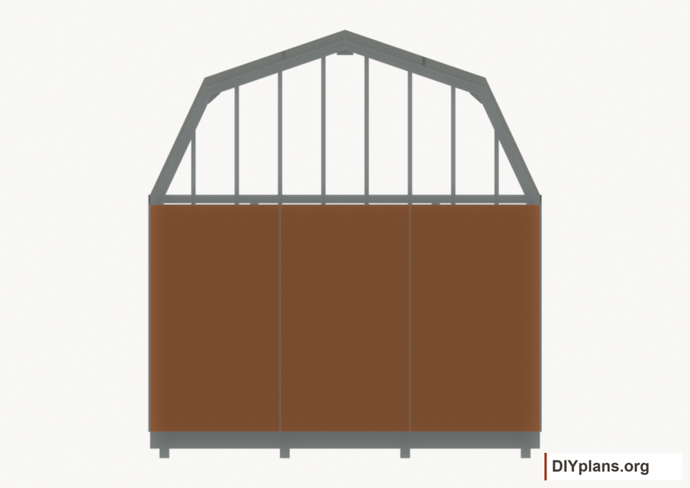
- Start from the drawing datum and align the marked factory edges and opening cuts.
- Maintain the selected product edge clearances, panel gaps and vertical groove direction.
- Fasten into the marked framing with the selected panel schedule; keep drainage and flashing laps open.

Check: Panel joints have their required backing and clearances; opening cuts match the frame.
Step 52 Fasten the front wall siding
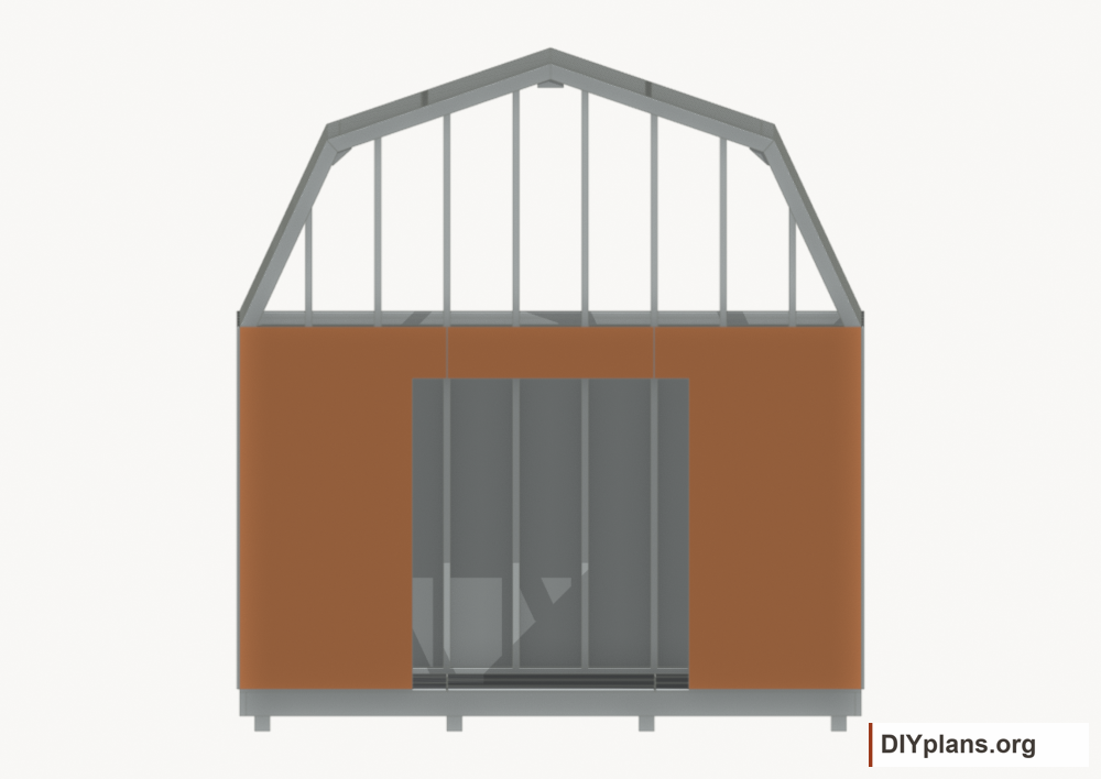
- Start from the drawing datum and align the marked factory edges and opening cuts.
- Maintain the selected product edge clearances, panel gaps and vertical groove direction.
- Fasten into the marked framing with the selected panel schedule; keep drainage and flashing laps open.
Check: Panel joints have their required backing and clearances; opening cuts match the frame.
Step 53 Fit the gable siding panels
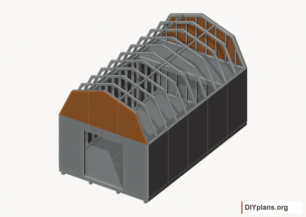
- Fit the labeled shaped panels to the front and rear roof outlines.
- Keep the wall-to-gable seam at Z = 84 inches and maintain the required joint gaps.
- Preserve vertical grooves and complete the selected fastening and seam-flashing detail.
Check: Both gables fit their roof outlines and the horizontal seams can drain.
Step 54 Cut and mark the roof panels


- 4 roof sheathing panel: 1/2 plywood, 75 15/16 in long, actual section 1/2 x 47 3/4 in.
- 2 roof sheathing panel: 1/2 plywood, 95 7/8 in long, actual section 1/2 x 47 3/4 in.
- 4 roof sheathing panel: 1/2 plywood, 75 15/16 in long, actual section 1/2 x 23 15/16 in.
- 2 roof sheathing panel: 1/2 plywood, 95 7/8 in long, actual section 1/2 x 23 15/16 in.
- 4 roof sheathing panel: 1/2 plywood, 75 15/16 in long, actual section 1/2 x 30 3/4 in.
- 2 roof sheathing panel: 1/2 plywood, 95 7/8 in long, actual section 1/2 x 30 3/4 in.
- Use the exact slope-width blanks and sheet allocation. Keep the panel strength direction and supported joints shown.
- Mark each lower or upper facet and front-to-rear position before taking panels to the roof.

Check: All pieces are marked with their matching cut-list IDs and reference edges.
Step 55 Fasten the roof sheathing
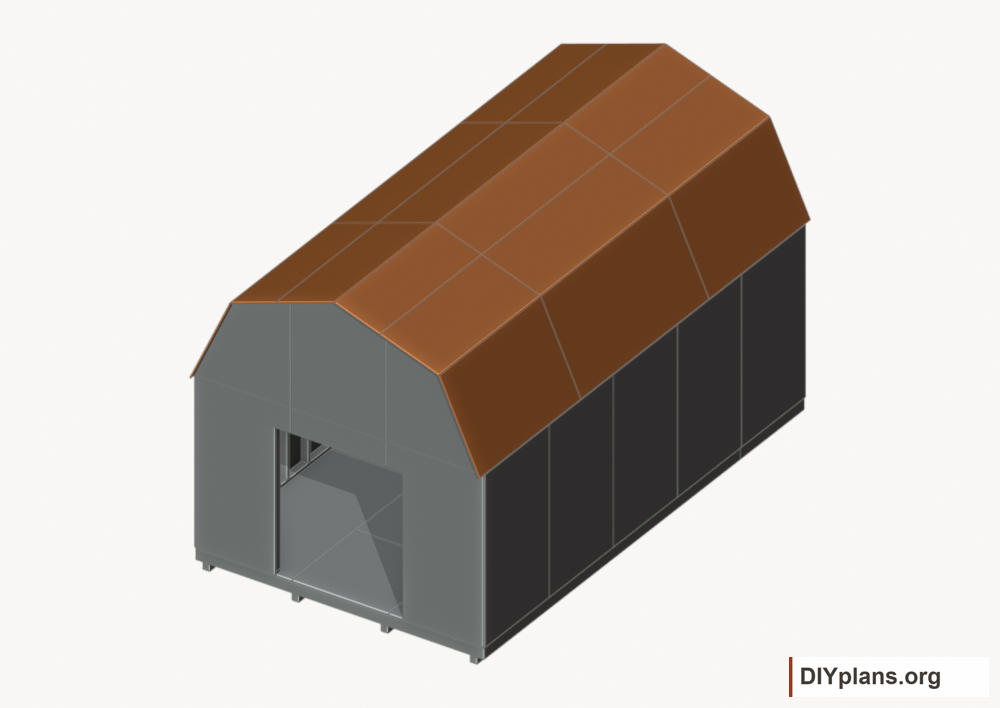
- Place the panels on their labeled roof facets with the specified edge gaps and front/rear overhangs.
- Keep panel joints over the framing and complete the selected edge-support and nailing details.
- Use stable roof-access equipment and fall protection; keep all roof frames restrained during sheathing.
Check: All four roof facets are sheathed with supported joints and aligned overhangs.
Step 56 Fit the eave drip edges
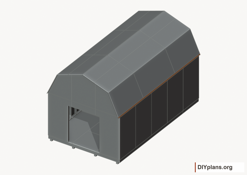
- Install the selected eave metal before the underlayment, keeping the outer return clear of the siding face.
- Follow the product instructions for hidden laps, fastening, exposed coverage and edge terminations.
- Use the listed roof areas and lengths to choose product quantities. Add the manufacturer's required overlaps and cutting allowance.
- Check each completed transition before concealing it with the next layer.

Check: This layer follows the selected roof system and sheds water onto the layer below.
Step 57 Lay the roof underlayment
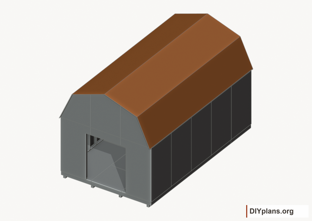
- Lay the selected membrane from lower to upper courses with its required side and end laps.
- Follow the product instructions for hidden laps, fastening, exposed coverage and edge terminations.
- Use the listed roof areas and lengths to choose product quantities. Add the manufacturer's required overlaps and cutting allowance.
- Check each completed transition before concealing it with the next layer.
Check: This layer follows the selected roof system and sheds water onto the layer below.
Step 58 Fit the rake drip edges
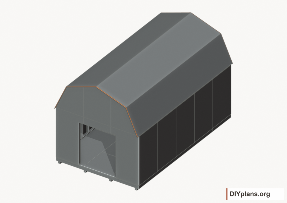
- Fit the rake metal in the lap order required by the selected roof system.
- Follow the product instructions for hidden laps, fastening, exposed coverage and edge terminations.
- Use the listed roof areas and lengths to choose product quantities. Add the manufacturer's required overlaps and cutting allowance.
- Check each completed transition before concealing it with the next layer.
Check: This layer follows the selected roof system and sheds water onto the layer below.
Step 59 Shingle the lower roof facets
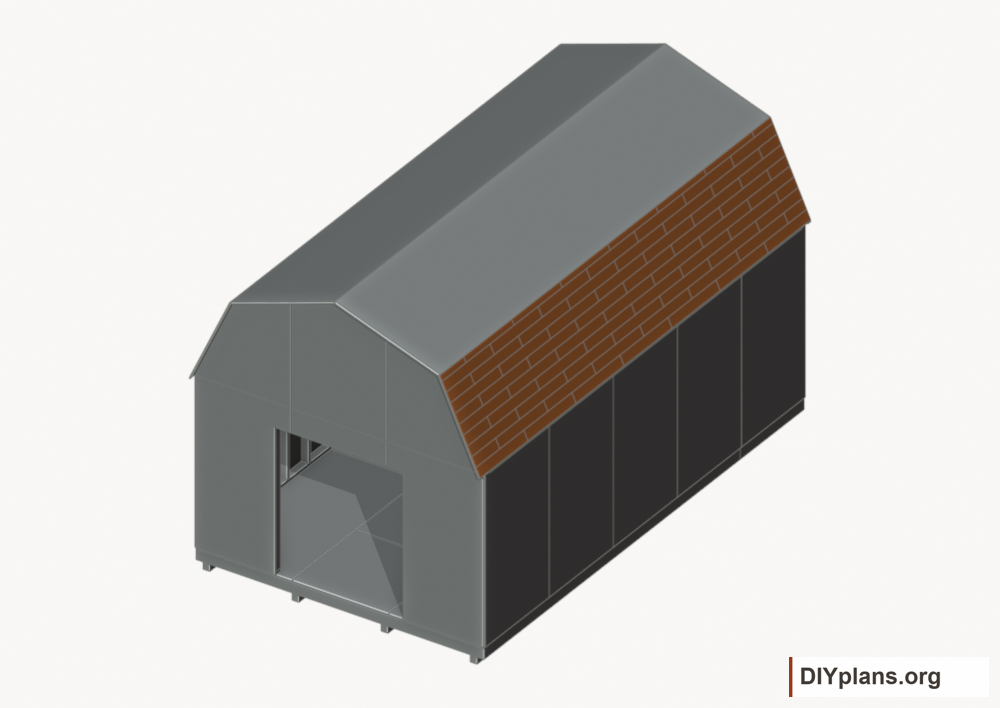
- Install the selected starter and lower field courses, working from eave toward knee.
- Follow the product instructions for hidden laps, fastening, exposed coverage and edge terminations.
- Use the listed roof areas and lengths to choose product quantities. Add the manufacturer's required overlaps and cutting allowance.
- Check each completed transition before concealing it with the next layer.
Check: This layer follows the selected roof system and sheds water onto the layer below.
Step 60 Flash the gambrel knees
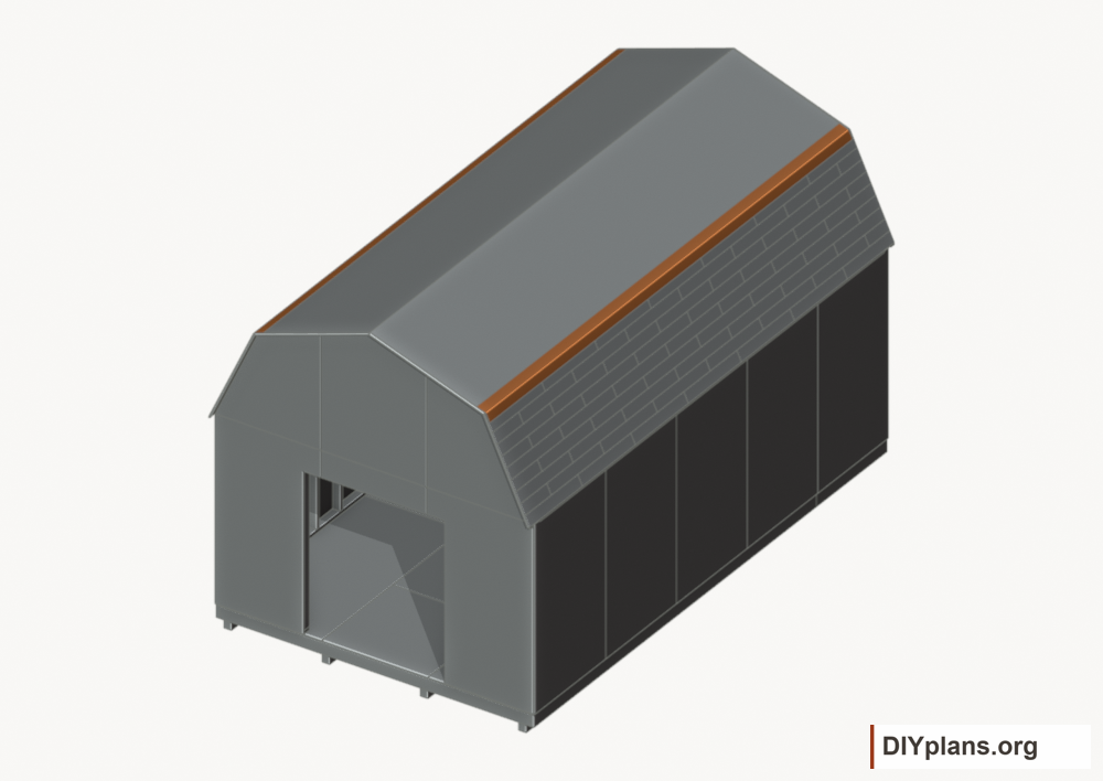
- Place the transition flashing above the lower shingles, with its upper flange beneath the upper field.
- Follow the product instructions for hidden laps, fastening, exposed coverage and edge terminations.
- Use the listed roof areas and lengths to choose product quantities. Add the manufacturer's required overlaps and cutting allowance.
- Check each completed transition before concealing it with the next layer.
Check: This layer follows the selected roof system and sheds water onto the layer below.
Step 61 Shingle the upper roof facets

- Work from each knee toward the ridge using the selected exposure and fastening pattern.
- Follow the product instructions for hidden laps, fastening, exposed coverage and edge terminations.
- Use the listed roof areas and lengths to choose product quantities. Add the manufacturer's required overlaps and cutting allowance.
- Check each completed transition before concealing it with the next layer.
Check: This layer follows the selected roof system and sheds water onto the layer below.
Step 62 Finish the ridge
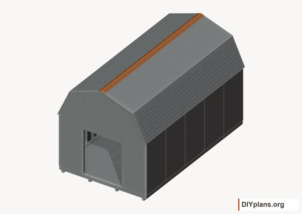
- Install the designed ridge closure or ventilation, then lay caps with the selected exposure and laps.
- Follow the product instructions for hidden laps, fastening, exposed coverage and edge terminations.
- Use the listed roof areas and lengths to choose product quantities. Add the manufacturer's required overlaps and cutting allowance.
- Check each completed transition before concealing it with the next layer.
Check: This layer follows the selected roof system and sheds water onto the layer below.
Step 63 Cut and lay out the door leaves


- Measure the completed opening before cutting the 31 11/16 by 71 5/8-inch leaves.
- 1 left t1-11 door skin: 5/8 T1-11 siding panel, 71 5/8 in long, actual section 5/8 x 31 11/16 in.
- 1 right t1-11 door skin: 5/8 T1-11 siding panel, 71 5/8 in long, actual section 5/8 x 31 11/16 in.
- 1 left exterior door stile: 2x4, 71 5/8 in long, actual section 1 1/2 x 3 1/2 in.
- 1 left exterior door stile: 2x4, 71 5/8 in long, actual section 1 1/2 x 3 1/2 in.
- 1 left exterior door bottom rail: 2x4, 24 11/16 in long, actual section 1 1/2 x 3 1/2 in.
- 1 left exterior door top rail: 2x4, 24 11/16 in long, actual section 1 1/2 x 3 1/2 in.
- 2 right exterior door stile: 2x4, 71 5/8 in long, actual section 1 1/2 x 3 1/2 in.
- 1 right exterior door bottom rail: 2x4, 24 11/16 in long, actual section 1 1/2 x 3 1/2 in.
- 1 right exterior door top rail: 2x4, 24 11/16 in long, actual section 1 1/2 x 3 1/2 in.
- 1 left exterior door middle rail: 2x4, 24 11/16 in long, actual section 1 1/2 x 3 1/2 in.
- Use the matching cut list for the remaining distinct sizes.
- Keep the T1-11 grooves vertical and the stiles and rails on the exterior face.
- Resolve skin fastening, sag resistance and rated hinge attachments before assembling the leaves.

Check: All pieces are marked with their matching cut-list IDs and reference edges.
Step 64 Fit the door jambs and head
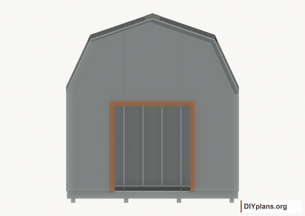
- 2 exterior 2x4 door jamb: 2x4, 72 in long, actual section 1 1/2 x 3 1/2 in.
- 1 exterior 2x4 door head: 2x4, 71 in long, actual section 1 1/2 x 3 1/2 in.
- Seat the jambs and head against their intended backing and align their outer faces with the exterior door framing.
- Integrate the head flashing and recheck the clear opening before drilling the selected hinge pattern.
Check: The jambs are plumb, the head is level and the hinge backing is ready.
Step 65 Build and hang the left door
Play movementStop movement

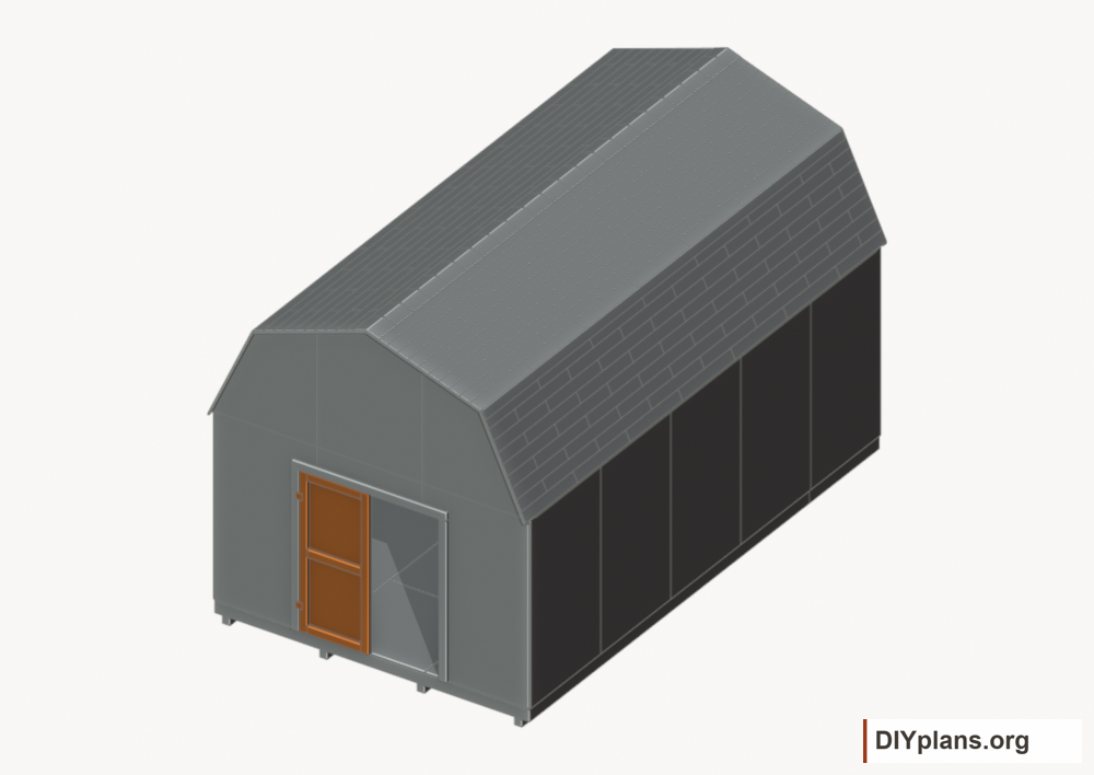
- Assemble the leaf flat with exterior stiles and rails; clamp square and fasten with the resolved door detail.
- Support the leaf on blocks while fastening the selected hinges into the specified backing.
- Set 1/8-inch side gaps, 1/8-inch top gap and 1/4-inch bottom gap; leave 3/8 inch between leaves.
- Check hinge travel and sag before removing the supports.
Check: The leaf holds its clearances and operates on the selected hardware without rubbing.
Step 66 Build and hang the right door
Play movementStop movement

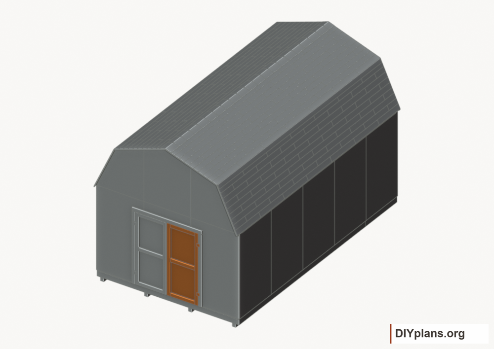
- Assemble the leaf flat with exterior stiles and rails; clamp square and fasten with the resolved door detail.
- Support the leaf on blocks while fastening the selected hinges into the specified backing.
- Set 1/8-inch side gaps, 1/8-inch top gap and 1/4-inch bottom gap; leave 3/8 inch between leaves.
- Check hinge travel and sag before removing the supports.
Check: The leaf holds its clearances and operates on the selected hardware without rubbing.
Step 67 Fit the door meeting strip
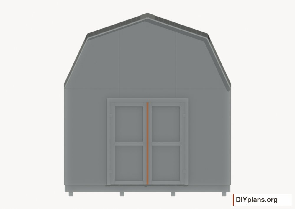
- 1 door meeting astragal over exterior frames: 1x2, 71 5/8 in long, actual section 3/4 x 1 1/2 in.
- Close and align both leaves, then attach the strip to the designated active leaf only.
- Keep the leaf-opening order, latch and selected weather seals clear through their full travel.
Check: The strip covers the meeting gap without binding the opposite leaf.
Step 68 Fit the pull and latch
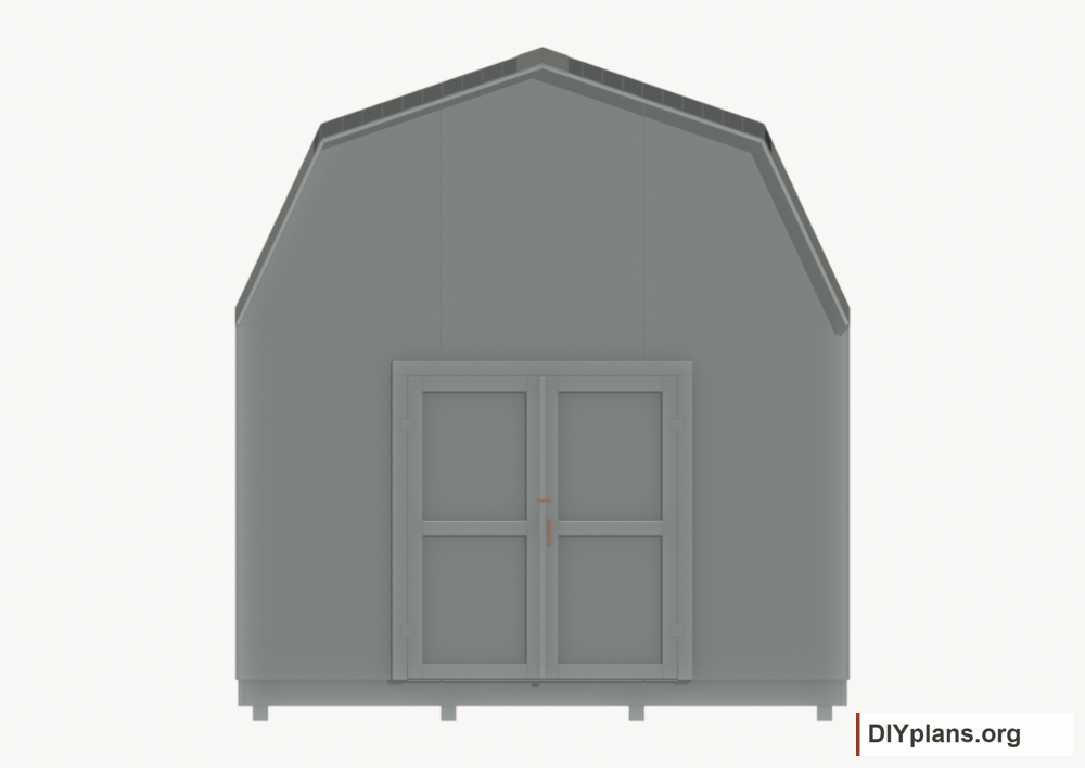
- Fit the selected pull, latch and fixed-leaf restraints into the specified solid backing.
- Follow the hardware manufacturer's fastener and edge-distance instructions. Confirm the hinge, handle and latch quantities before ordering.
- Operate the doors and hardware open and closed, and correct sag or binding.
Check: Both leaves close, secure and reopen freely.
Step 69 Fit the corner trim
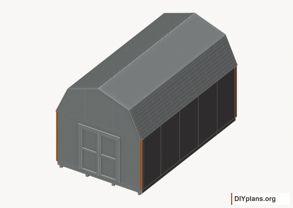

- 2 corner front or rear trim: 1x4, 84 in long, actual section 3/4 x 3 1/2 in.
- 2 corner front or rear trim: 1x4, 84 in long, actual section 3/4 x 3 1/2 in.
- 2 corner side trim: 1x4, 84 in long, actual section 3/4 x 3 1/2 in.
- 2 corner side trim: 1x4, 84 in long, actual section 3/4 x 3 1/2 in.
- Fit each front or rear board over the edge of its side return, seating both boards against the measured T1-11 faces.
- Preserve required bottom clearances and drainage paths; seal cut ends and fasten into the specified backing.
Check: Every corner return closes without a gap and preserves the selected weather detail.
Step 70 Cover the wall-to-gable seams
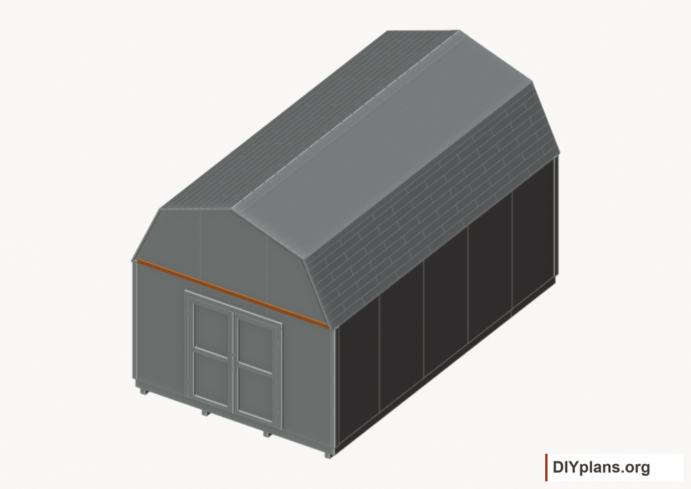

- 1 gable-to-wall seam trim: 1x4, 139 3/4 in long, actual section 3/4 x 3 1/2 in.
- 1 gable-to-wall seam trim: 1x4, 139 3/4 in long, actual section 3/4 x 3 1/2 in.
- Center the continuous seam boards over the Z = 84-inch panel joint, fitting their ends between the corner trims.
- Preserve the flashing and drainage detail behind the boards; fasten into the specified backing and finish cut ends.
Check: Both horizontal seams are covered without replacing their flashing.
Step 71 Seal and finish the exterior
- Allow wood and panels to dry to the coating manufacturer’s limits.
- Seal only required joints; keep drainage and ventilation openings clear.
- Prime exposed cuts, apply the selected finish and recheck door operation after coating.

Check: The exterior has its required finish and all intended drainage paths remain open.
Step 72 Inspect before use
- Compare foundation-to-roof connections, panel fastening and permanent bracing with the completed construction details.
- Check wall plumb, roof alignment, flashing, trim support and both doors.
- Remove temporary bracing only where the permanent structure replaces it.
- Complete required inspections and loft access, edge protection and permitted-load documentation before use.
Check: Required construction decisions and inspections are complete before occupancy or storage.