




Before you start
- Specify roof joints and restraint, shaped-panel cuts, door connections, site foundations and loft capacity before construction.
- Use full 96″ boards for the 96″ posts; precut wall studs are too short.
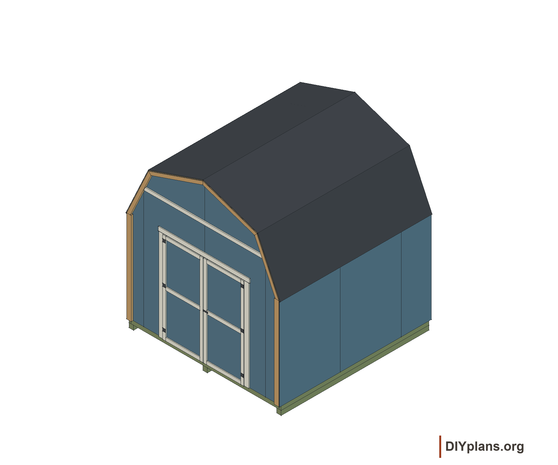
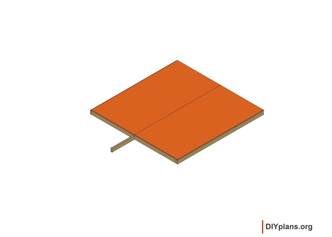
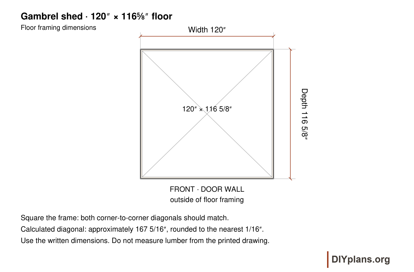
- The floor is 120″×116⅝″. All measurements below are inches.
Dimensions and opening sizes
- Floor width
- 120 in
- Floor depth
- 116 5/8 in
- Wall framing depthNominal 2×4; actual 1½″×3½″.
- 3 1/2 in
- Side-wall frame heightAbove the finished floor.
- 71 3/4 in
- Corner stud length
- 72 5/8 in
- Loft width
- 96 in
- Loft depth
- 48 in
- Loft bearing heightUnderside of the 7/16″ loft panel.
- 75 1/4 in
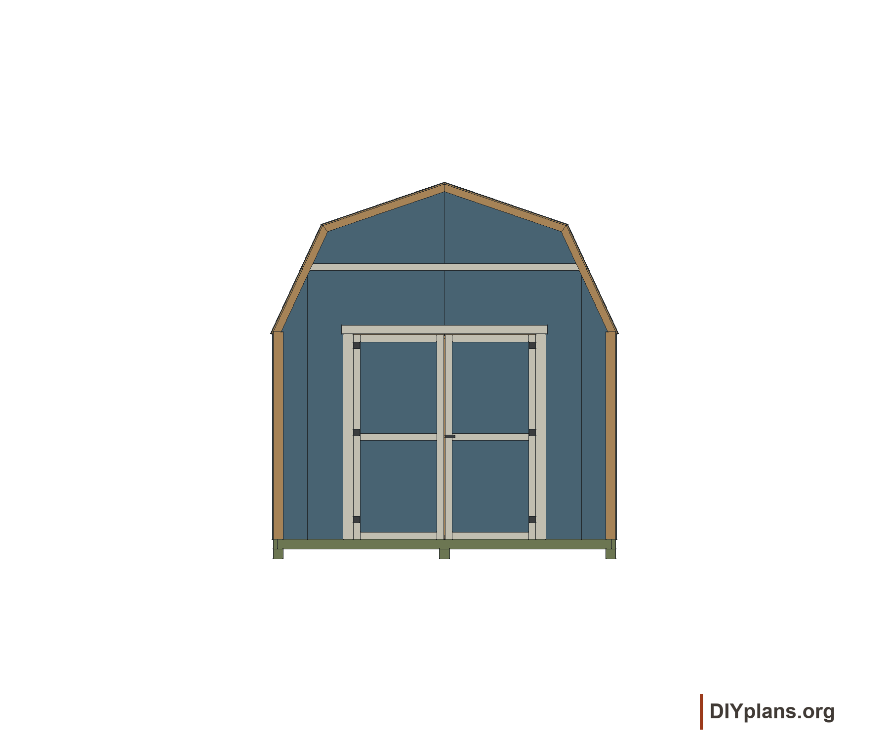
- Door opening widthDoor framing and hardware details need completion.
- 64 in
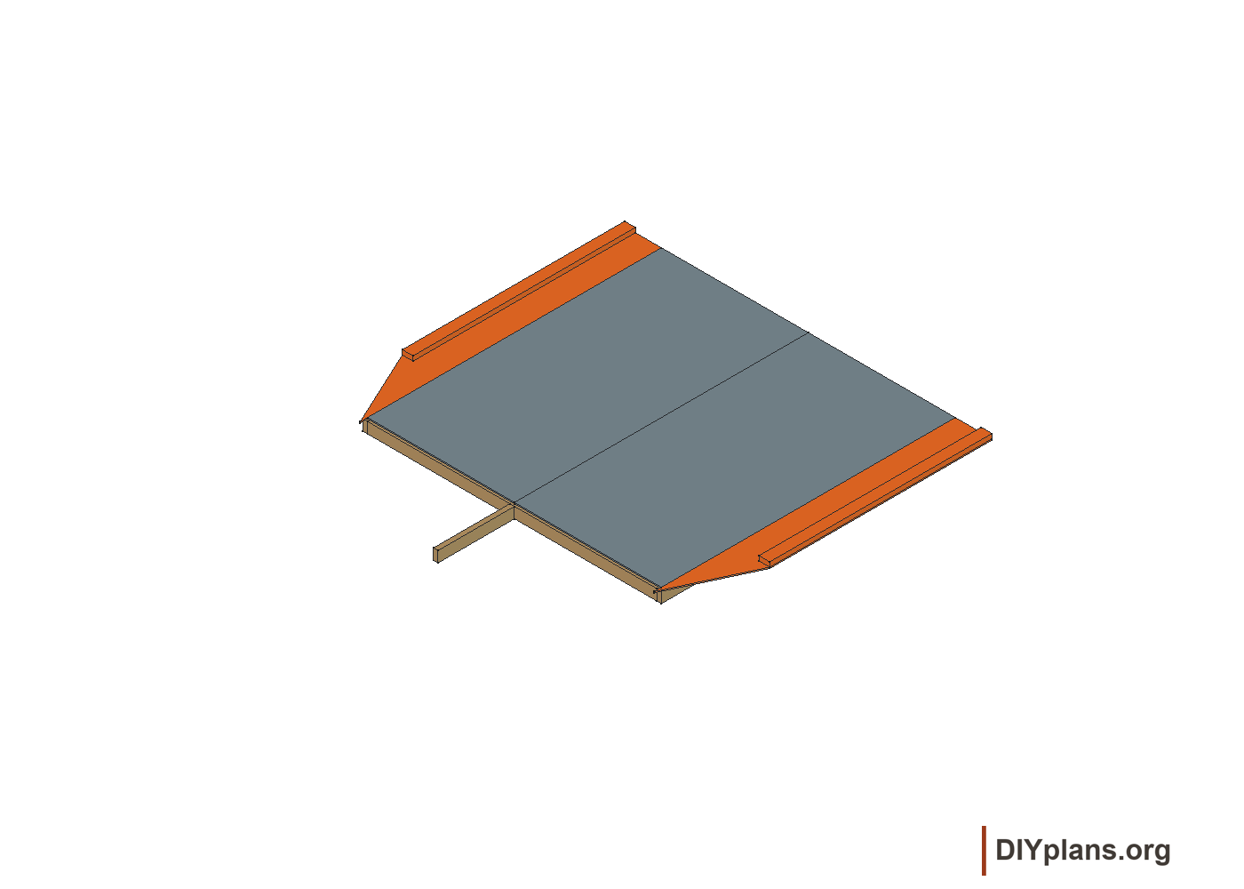
Shopping & cut lists
Get the shopping and cut lists
Includes all available CAD files, shopping lists and cut lists for every configuration of this plan. One payment, $19 USD.
Get the plan package · $19Secure checkout with Stripe. Your account is created after payment.
Already purchased? Sign in to access your plans.
Tools & equipment
- Phillips screwdriver
- drill-driver
- 3/8-inch drill bit
- #2 Phillips driver bit
- hammer
- level
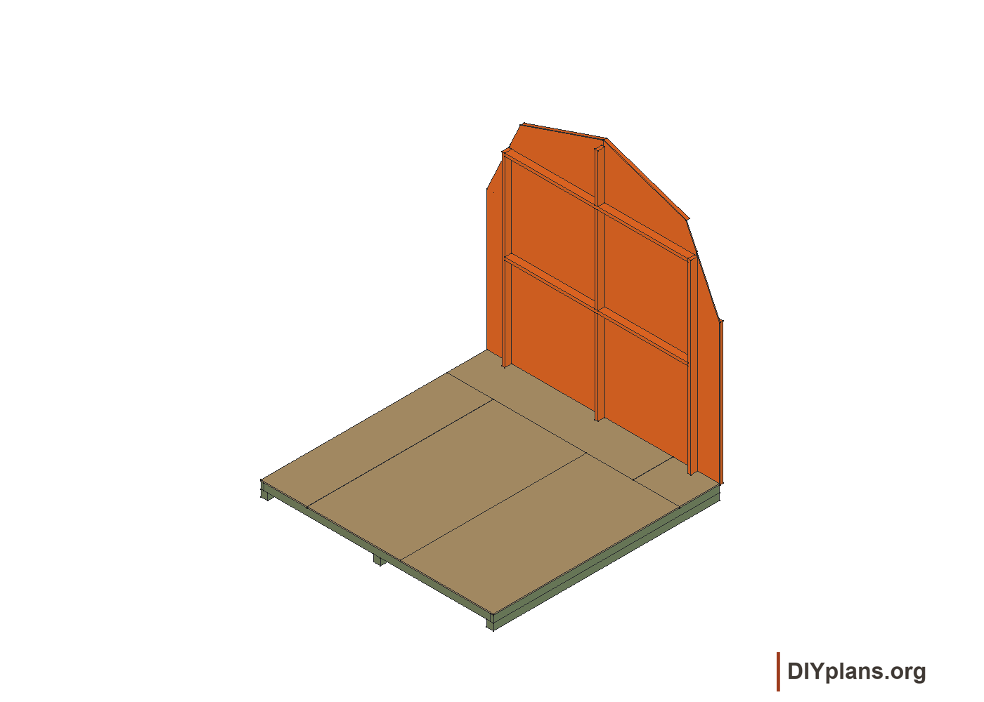
- pencil
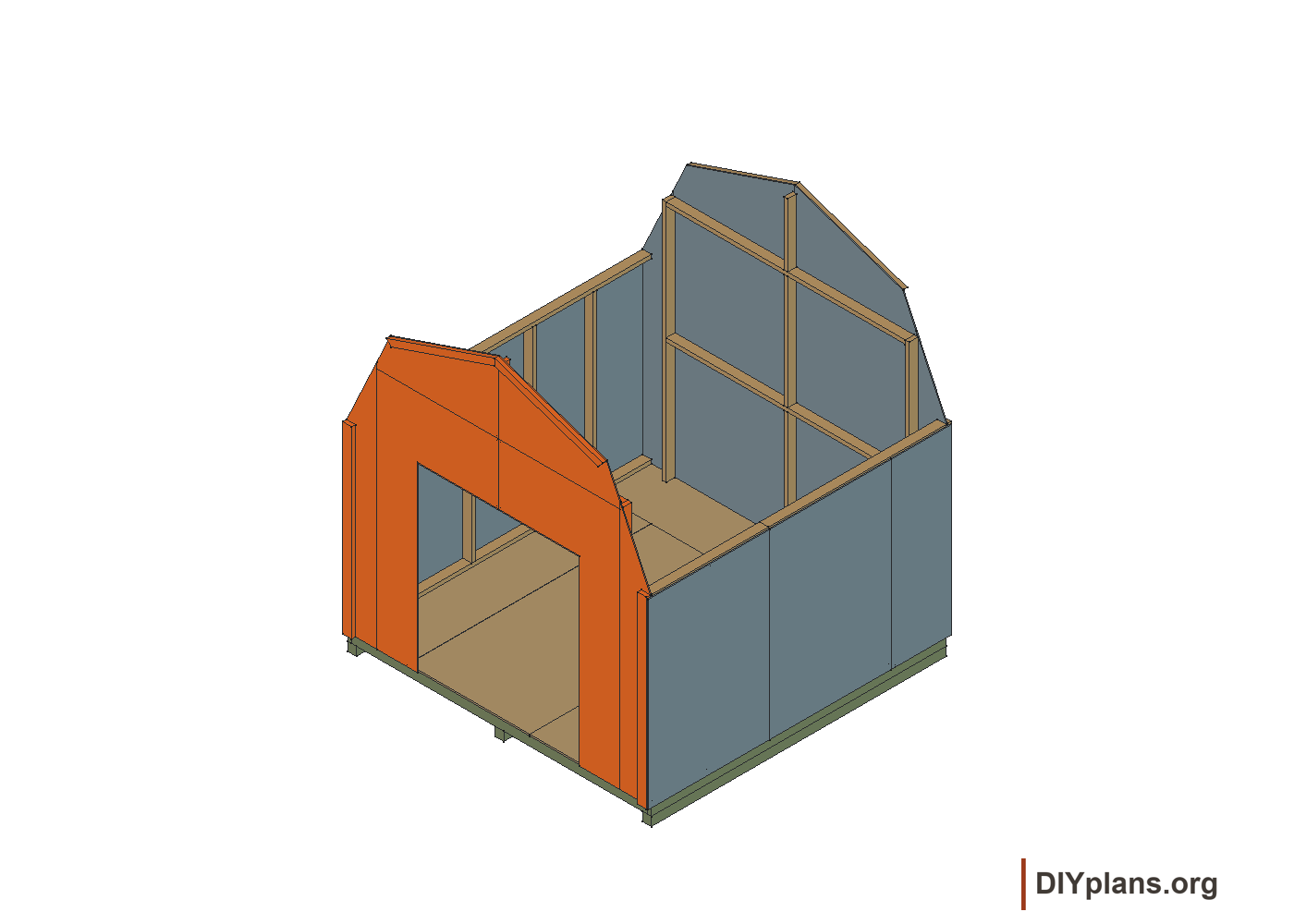
- tape measure
- square
- utility knife
- hooked shingle blades
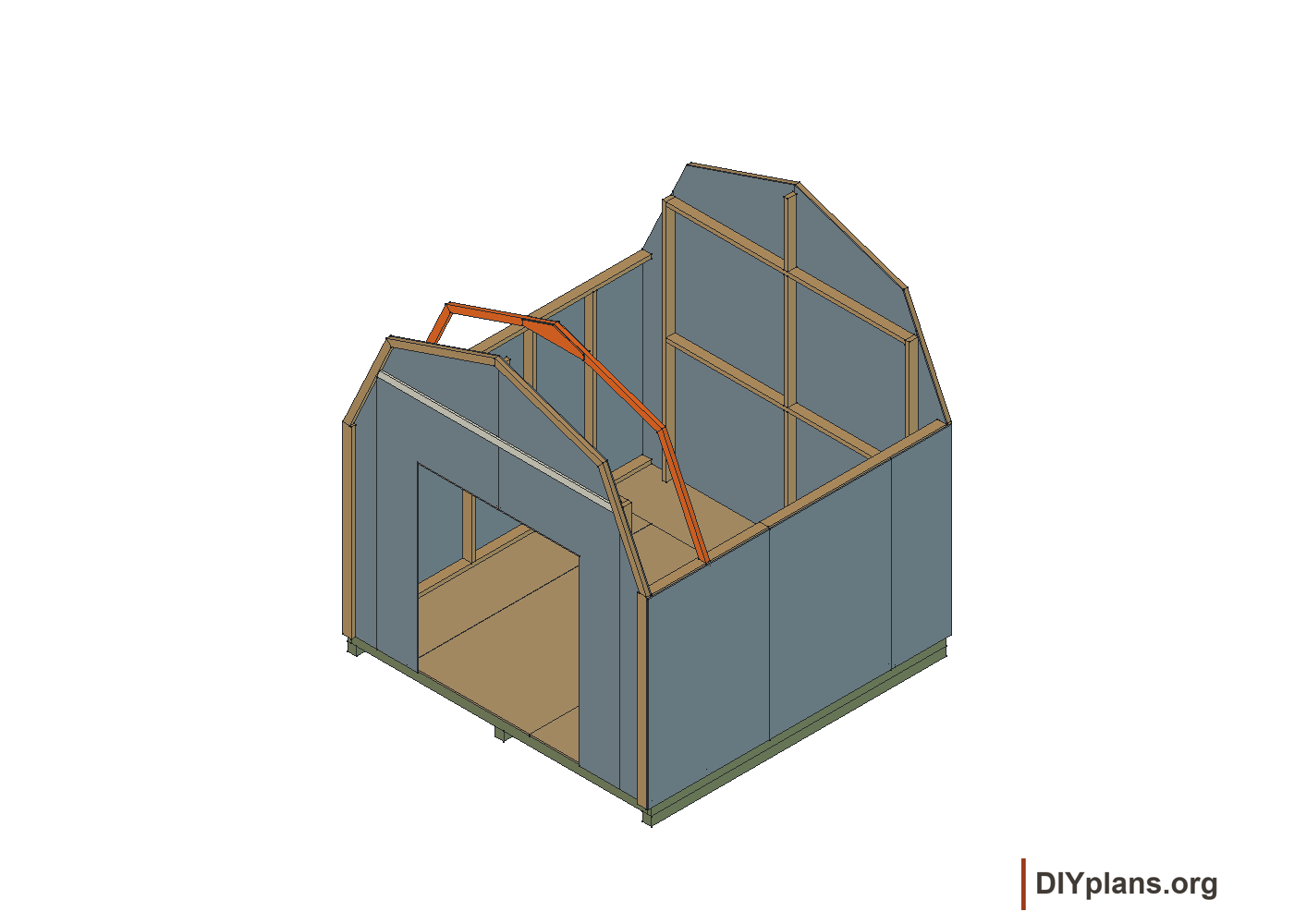
- caulk gun
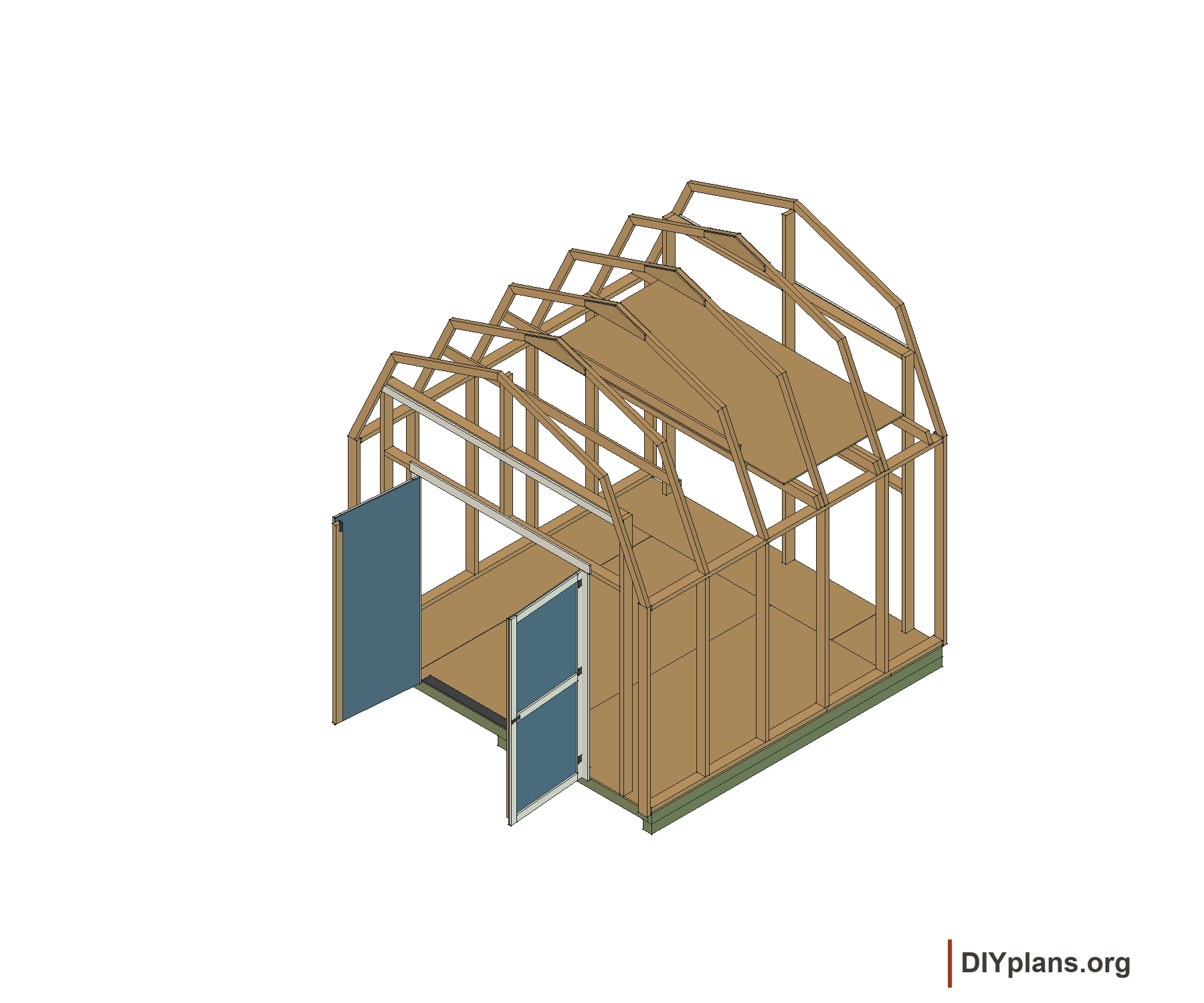
- paint tools
- safety glasses
- ladder
- circular saw and appropriate blade
- supported cutting surface
- straightedge and clamps
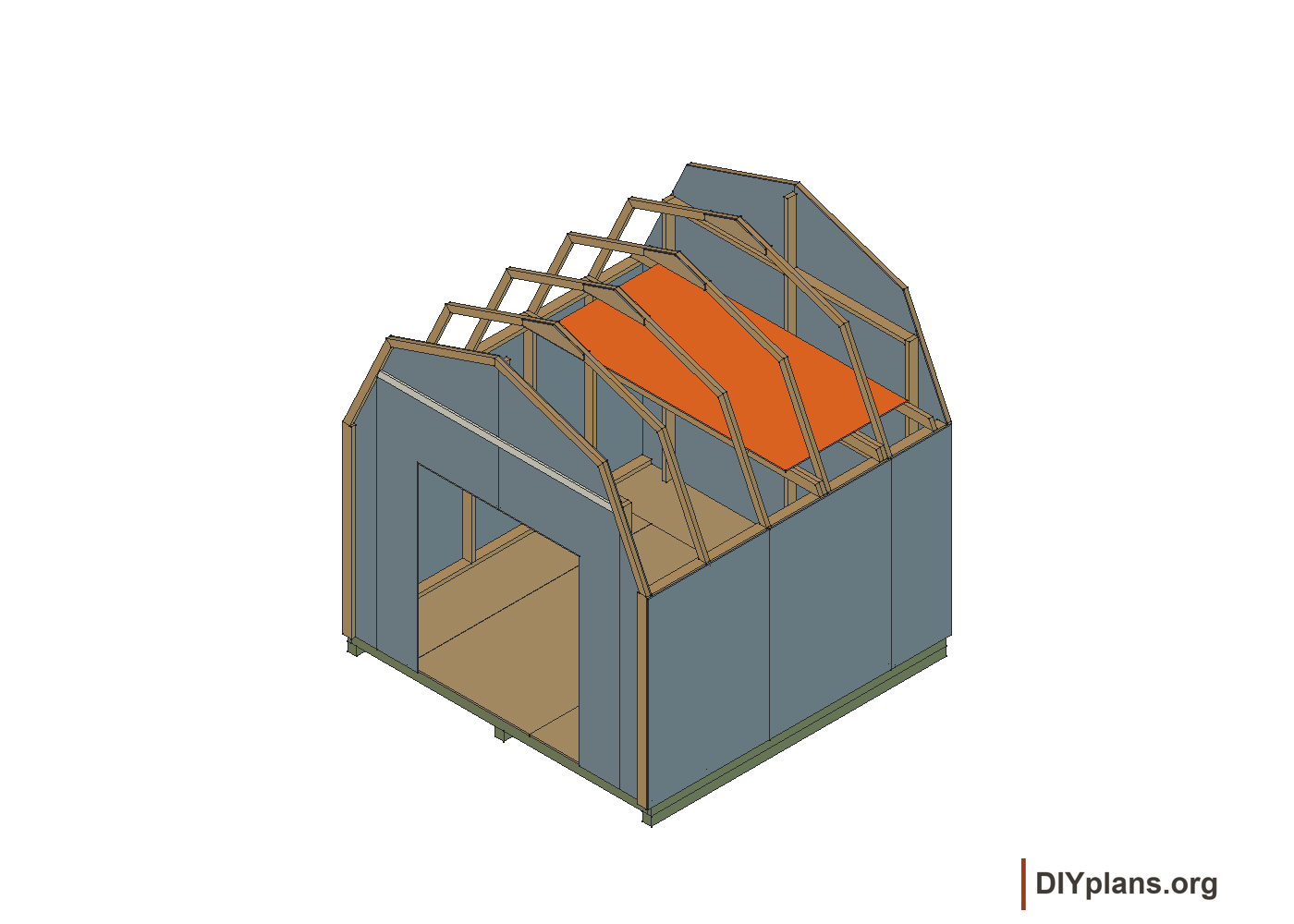
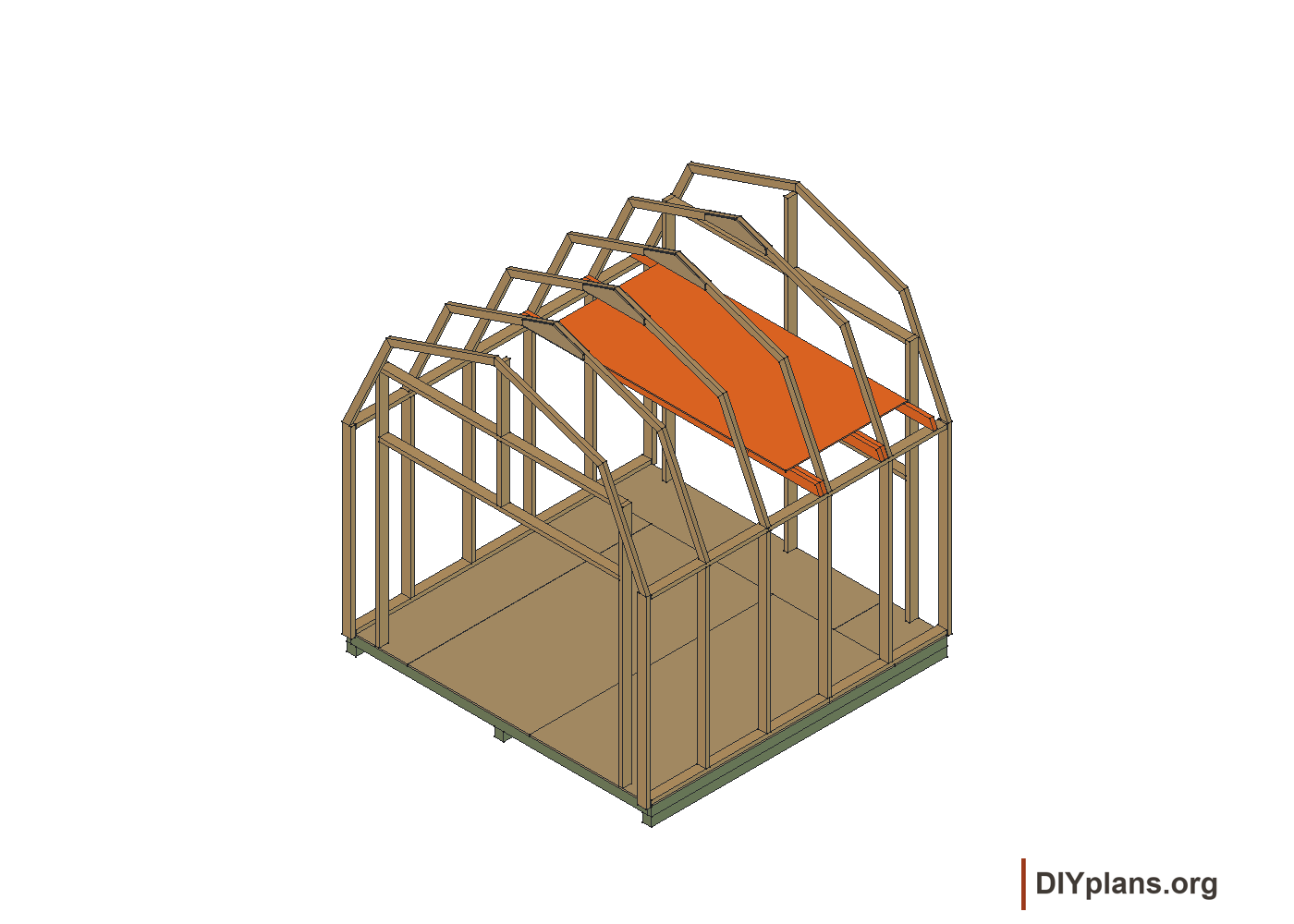
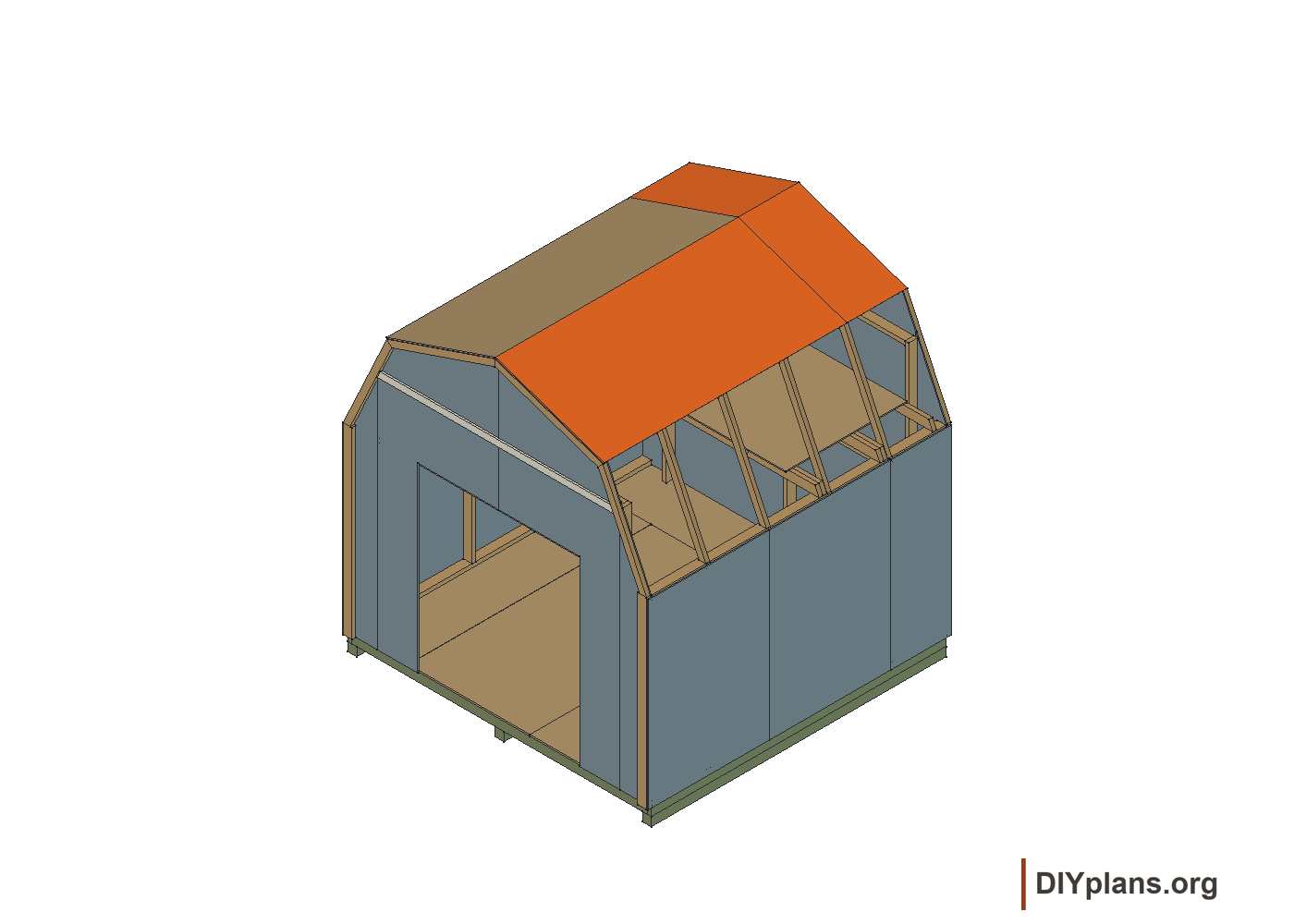
- hearing and dust protection
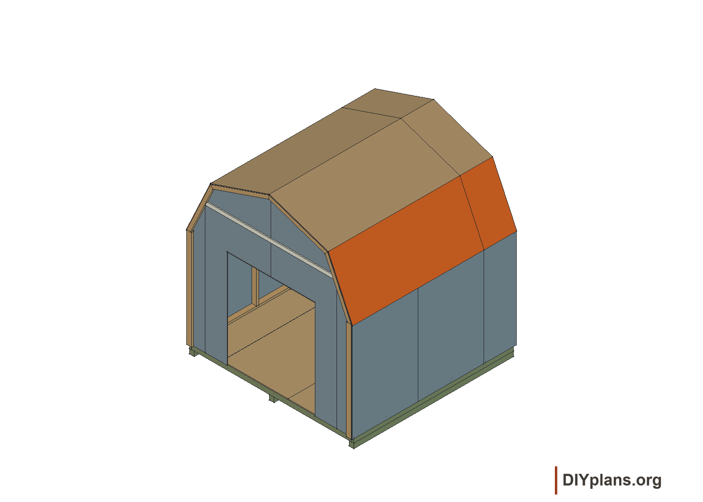
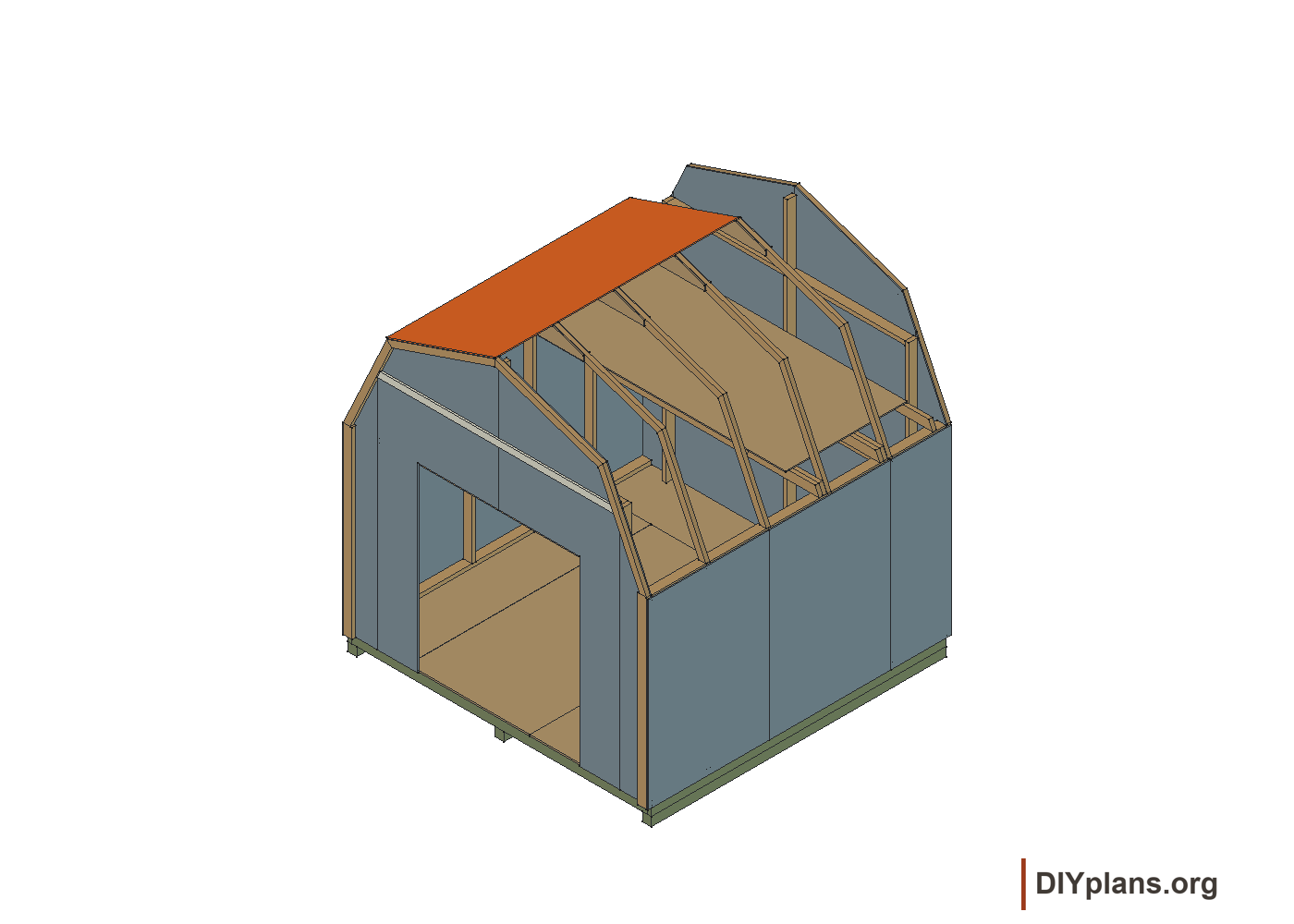
- tool belt or nail pouch
- tin snips for drip edge
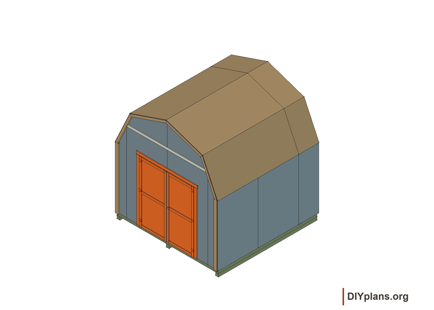
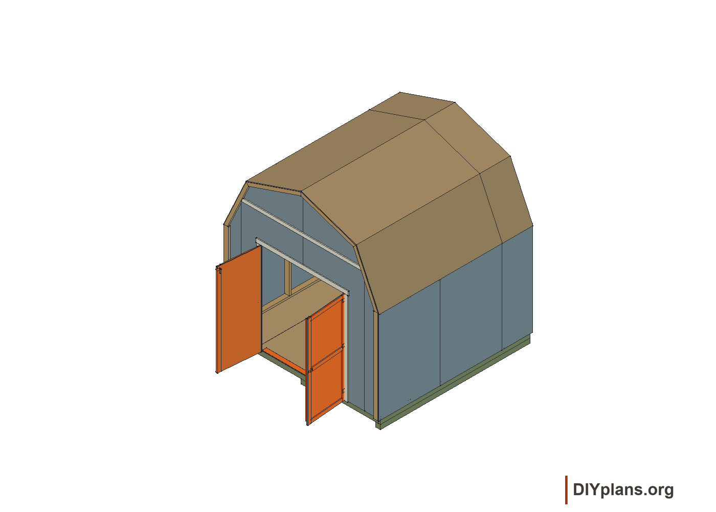
- chalk line
- nail gun with compatible nails
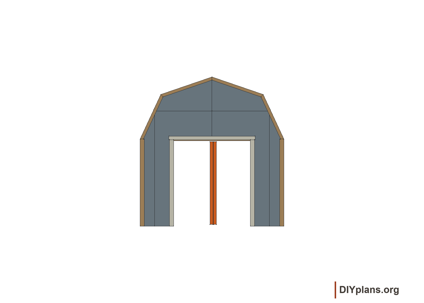
- gloves
BEFORE YOU BUILD
Use this work at your own risk
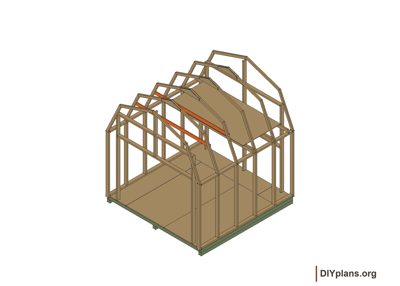
No person or organization makes any guarantee or warranty, express or implied, regarding this design, its documentation, digital files, or website views. They are not professional services and do not create an architect-client or other professional-client relationship. No promise is made about accuracy, completeness, reliability, code compliance, or fitness for your project.
Buildings and building projects are complex, and many things can go wrong. You are responsible for checking dimensions and site conditions, choosing suitable materials and methods, obtaining permits, following codes and manufacturer instructions, and getting qualified professional help when needed. To the fullest extent permitted by law, DIYPlans.org disclaims liability for damages resulting from use of this work. Read the FAQ about your responsibilities.
Instructions
01 Confirm the site and design
- Use the site measurements and fabrication drawings.
- Check that the 120 × 116⅝-inch floor footprint, roof overhang, door swing and working clearance fit the site.
- Confirm setbacks, foundation and anchor requirements, wind/snow conditions and permits.
- Choose a runner-supported wood floor or a separately designed concrete slab.
- Specify roof joints and restraint, panel cuts, door connections and structural details before building. The loft has no assigned load rating.
Check: Site, foundation and unresolved design details are documented.
02 Assemble tools and safety equipment
- every tool in the Tools section.
- Fit the drill with a #2 Phillips bit and keep the 3/8-inch bit for the barrel-bolt hole.
- Reserve the hooked utility blade for shingles and tin snips for drip edge.
- Set up a level, tape, framing square, pencil, and chalk line where they remain accessible.
- Plan for at least two people at wall-standing, rafter, roof-panel, door, and roofing work.
Check: Ladders and cutting supports are stable; lifting helpers are available.
03 Purchase materials
- the purchase list above.
- Order the selected floor package, wall stock, sheet goods, fasteners, glue and finish supplies from the Materials list.
- Specify lumber grades, panel ratings and fasteners before ordering.
- Keep product instructions and separate treated-wood floor fasteners from wall, roof and door fasteners.
Check: Stock and fasteners match the selected materials.
04 Cut and label the straight framing members
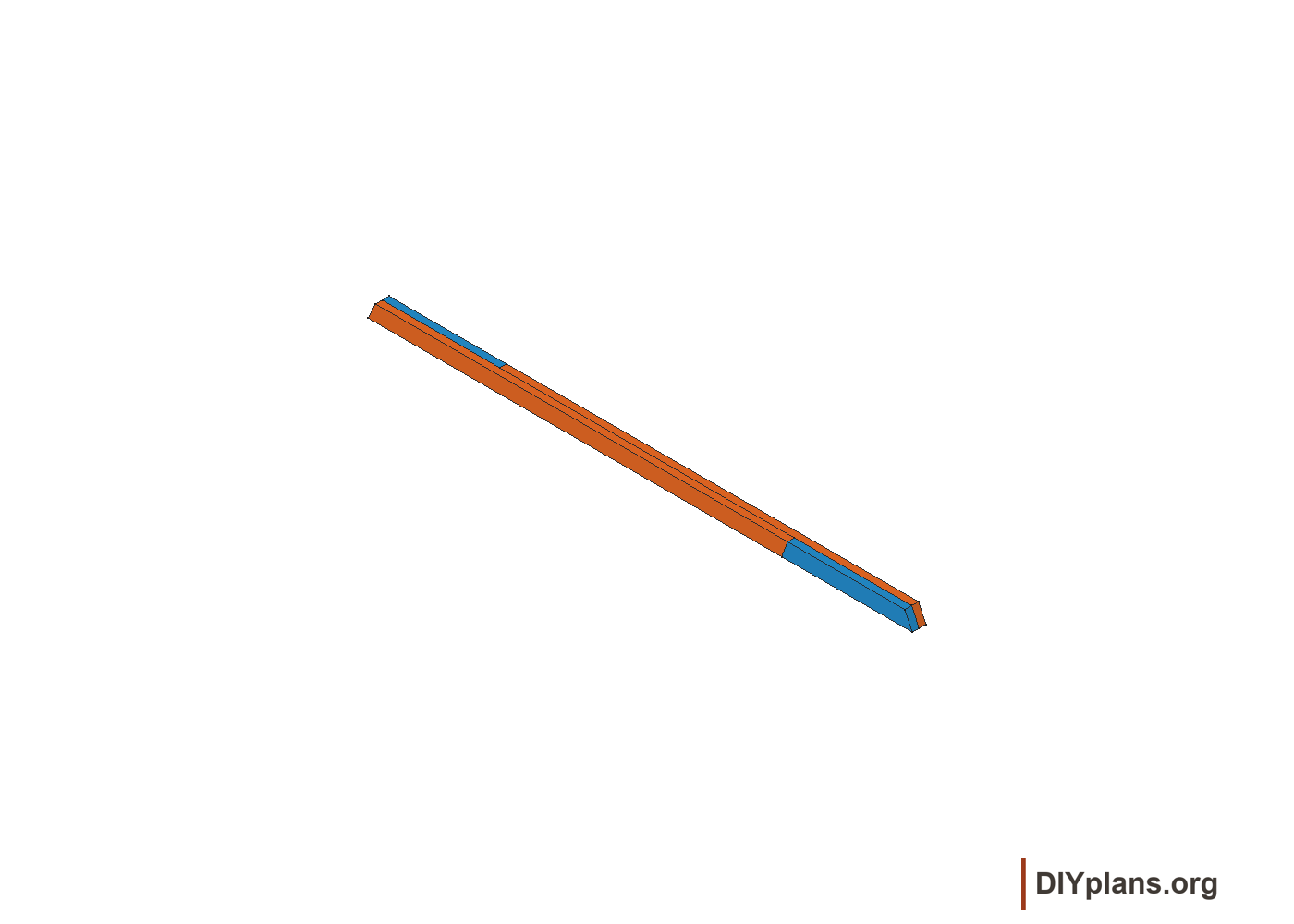
- Structural 2 × 4 stock for walls and corner studs; two 2 × 3 door-strip boards; cut allocations W01–W23; tape, square, saw and pencil.
- Use structural 2 × 4 stock with an actual 1½ × 3½-inch section.
- Follow W01–W23. Check usable board length, blade kerf and the waste side of each mark; the four end-wall posts (PT) need a full 96 inches.
- Cut four end-wall rails (PR) at 94½ inches, four end-wall posts (PT) at 96 inches and eight side-wall studs (OU) at 68¾ inches.
- Cut four short side-wall plates (NH) at 46¼ inches and four long plates (OZ) at 70¼ inches.
- Cut one lower back stud (NK) at 48 inches, one upper back stud (NC) at 45 inches, one front header stud (LV) at 22½ inches and two gable posts (CO) at 25 inches. Label both ends with code and length.
- From four additional 2 × 4 boards, cut four square-ended corner studs (OB) at 72⅝ inches.
- From two 2 × 3 boards, cut two 69-inch door weatherstrips (OO), actual 1½ × 2½ inches.
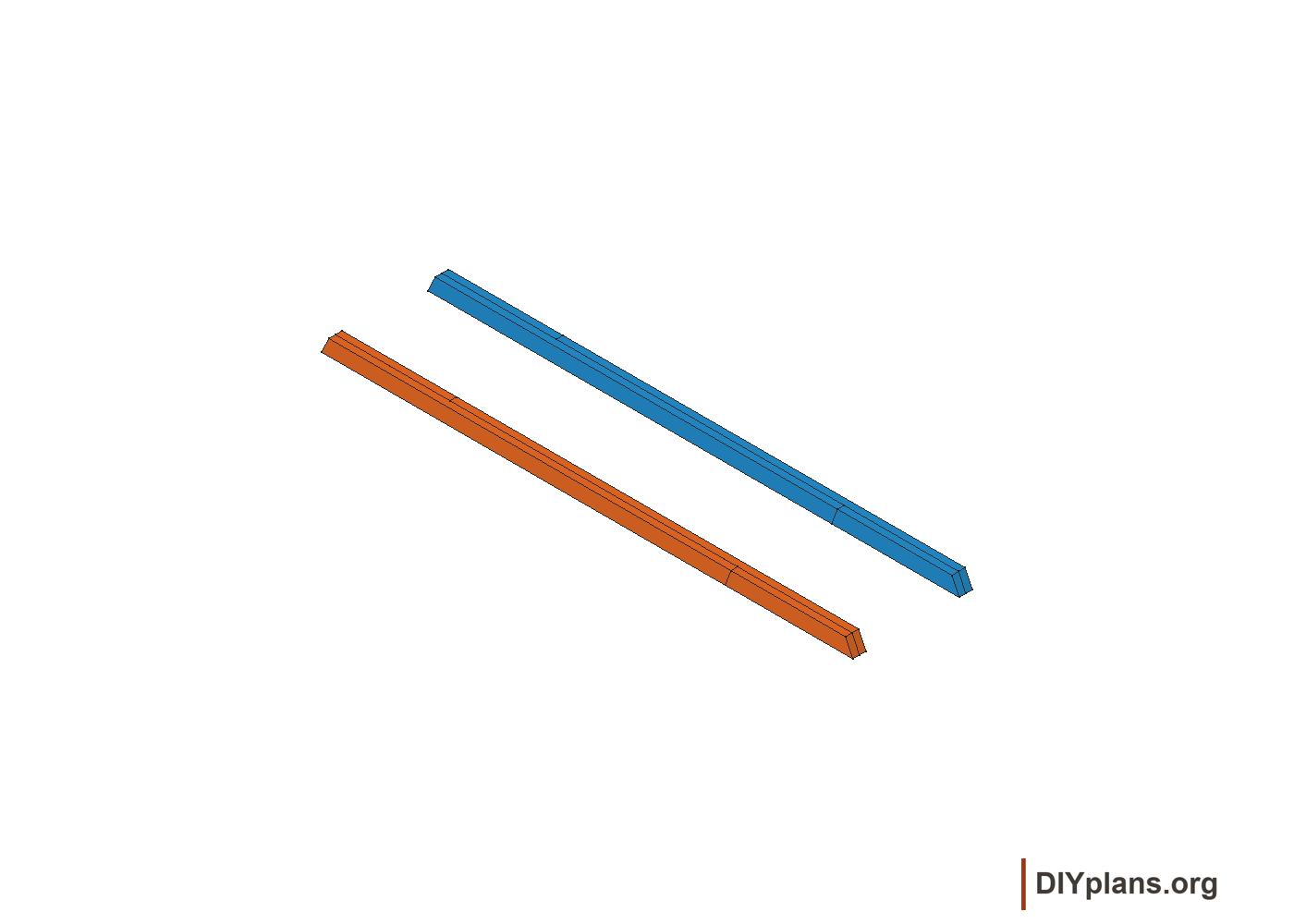
- Keep two full 1 × 4 × 96-inch collar ties (KP) for temporary supports and permanent installation. Cut one 1 × 3 × 5-inch spacer gauge (GAA).
- Group the parts by wall. Leave angled end rafters, trim, loft pieces and roof joints uncut until their listed details are resolved.
Check: All 33 wall-framing pieces are labeled, including four corner studs.
05 Cut the rectangular roof panels and prepare the loft panel
- tape measure, panel inventory.
- Confirm the specified rated 7/16″ panel product and its required span/grain orientation.
- Keep one 48″ × 96″ sheet whole for the loft.
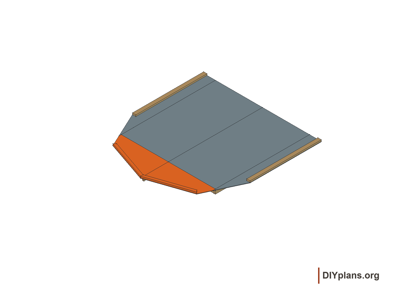
- From two roof sheets, rip one 45⅛″ × 96″ upper panel each. From two more sheets, rip one 41⅞″ × 96″ lower panel each.
- From the fifth roof sheet, crosscut four 23⅞″ bands along the 96″ direction. Rip two to 45⅛″ and two to 41⅞″. Check that the actual kerf and edge trimming fit before cutting the fourth band.
- Label all eight roof rectangles by dimensions on the concealed face. Keep them dry and flat. Cut square panel edges unless the chosen panel system specifically requires another edge treatment.
Check: Eight roof panels and one full loft panel match the cut list.
06 Prepare enclosure parts and sort the hardware
- tape measure, inventory checklist.
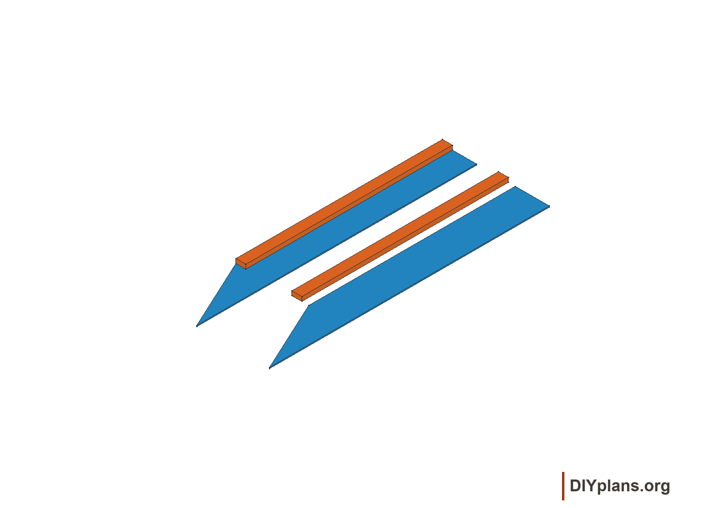
- Reserve two full 48 × 96-inch back panels. Cut four 48 × 72-inch side panels and two 23⅞ × 72-inch side panels from the seven-sheet allowance, preserving the required edge laps.
- Complete the cutting profiles for two left and two right wing panels, two left and two right gable panels, and the two front door-opening panels. Cut them from additional sheet stock only after their outlines and laps are resolved.
- Complete the door drawings before fabrication: leaf dimensions, siding, rails, stiles, hinge boards, hinges, fasteners and two ⅜-inch meeting-gap spacers. Build the left and right doors from those drawings.
- Sort fasteners by type and length. Confirm gauges, coatings and penetration against the connection schedule.
- Select and detail the threshold’s profile, drainage, position and attachment to the opening.
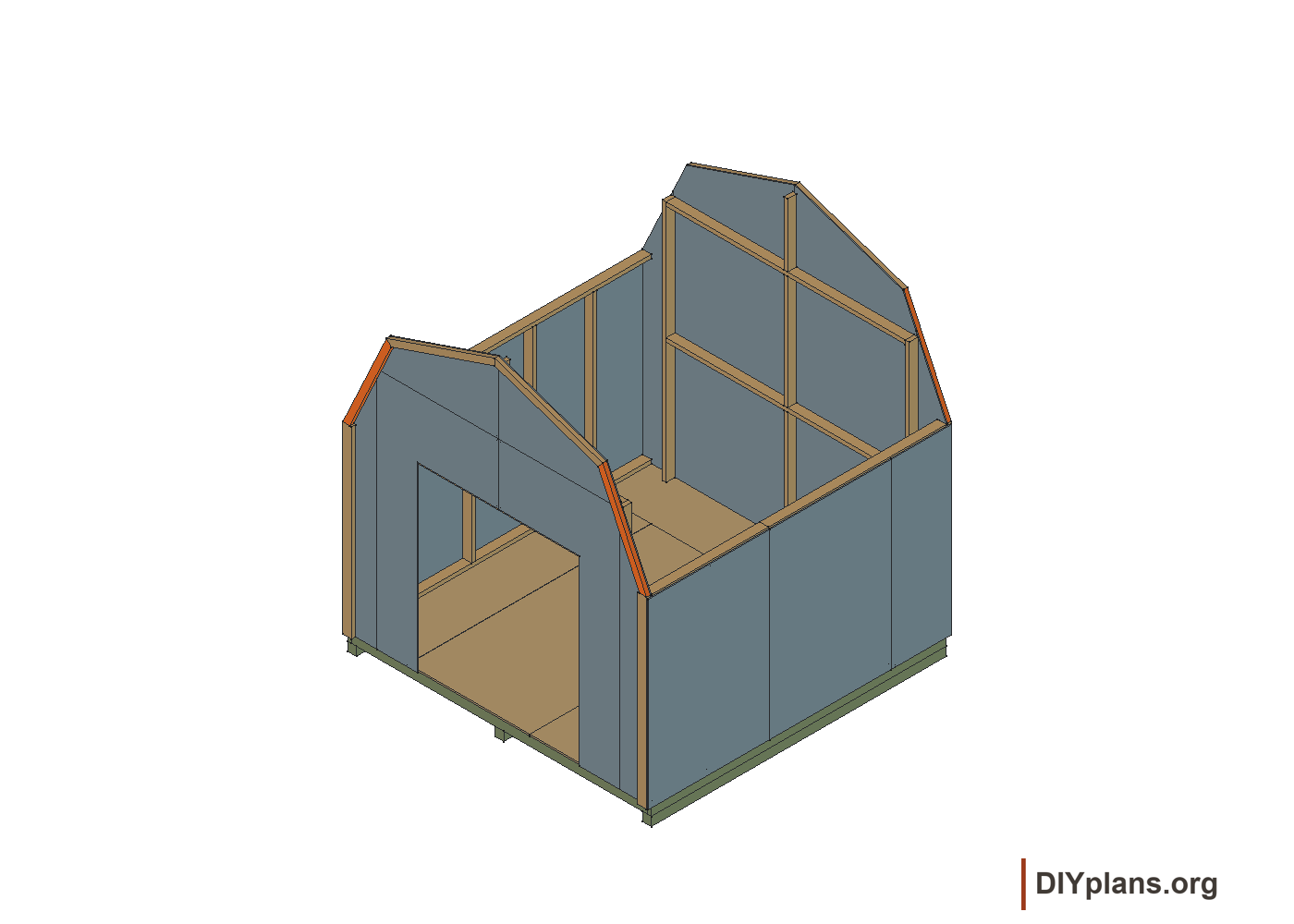
- Keep panel parts separate for assembly with corner studs in S23 and upper end rafters in S25.
Check: Required panel, door and threshold drawings are complete before fabrication.
07 Check framing alignment
- Use the framing drawing, part list and pencil.
- Place rafters directly above the side-wall studs (OU). Each wall member, including the gable posts (CO) and corner studs (OB), uses an actual 1½ × 3½-inch section.
- Connect all four corner studs to their wing panels and adjoining wall plates.
- Maintain the siding extension below the floor edge for drainage.
- Keep collar ties and loft beams at their specified positions; they form part of the roof restraint system.
Check: Rafters align with studs; all four corner assemblies are included.
08 Prepare runner supports
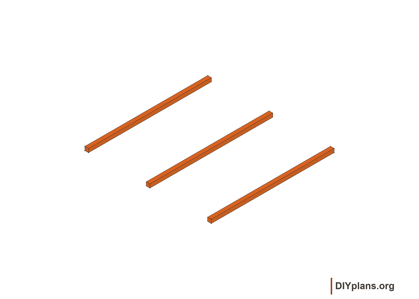
- three 4 x 4 x 116-5/8 runners, gravel/blocks/shims, level, tape.
- Set the three runners parallel in the 116⅝-inch direction. Mark their exact lateral locations from the selected foundation plan so the 120-inch-wide floor frame and its joints have adequate support. Resolve these locations before fastening.
- Place leveling supports 12 inches from runner ends and no more than 48 inches apart.
- Put gravel beneath concrete blocks for drainage; place asphalt-shingle shims only between runners and blocks/treated lumber, never against soil.
- Level only beneath the runners. Do not raise the system more than 16 inches with this method.
Check: Runners are level with one another and supported at every planned bearing point.
09 Concrete alternative hold point
- slab plan, four treated 2 x 4 x 10-foot sill boards, caulk, approved anchors.
- For a concrete floor, use a complete slab and sill drawing coordinated with the 120 × 116⅝-inch shed footprint and the door/threshold opening.
- Let concrete reach the specified strength and curing condition before drilling, installing anchors or loading the slab.
- Apply compatible exterior sill sealant beneath every treated sill plate.
- Install the selected anchors with the specified embedment, edge distances, spacing and tightening procedure.
- Stop if slab thickness, reinforcement, frost protection, anchor details or sill cuts are unresolved. These are site-specific design requirements.
Check: Slab and anchors meet the foundation specification before walls are installed.
10 Cut the wood-floor members
- eleven treated 2 x 4 x 120 boards, saw/cutting service, tape, square, pencil.
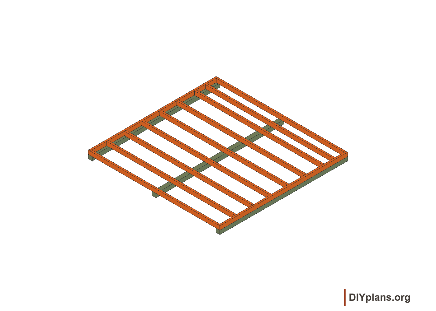
- Cut nine boards to 117 and two boards to 116-5/8 using the kerf allocation above.
- If reinforcing the floor, cut two additional boards to 117.
- Mark every piece with its finished length and reject split or badly crowned stock.
Check: All nine 117-inch crossmembers match; both 116⅝-inch rims match.
11 Lay out the floor frame
- cut floor members, tape, square, pencil.
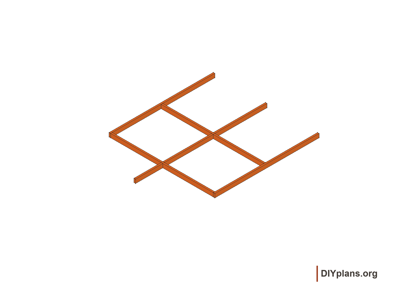
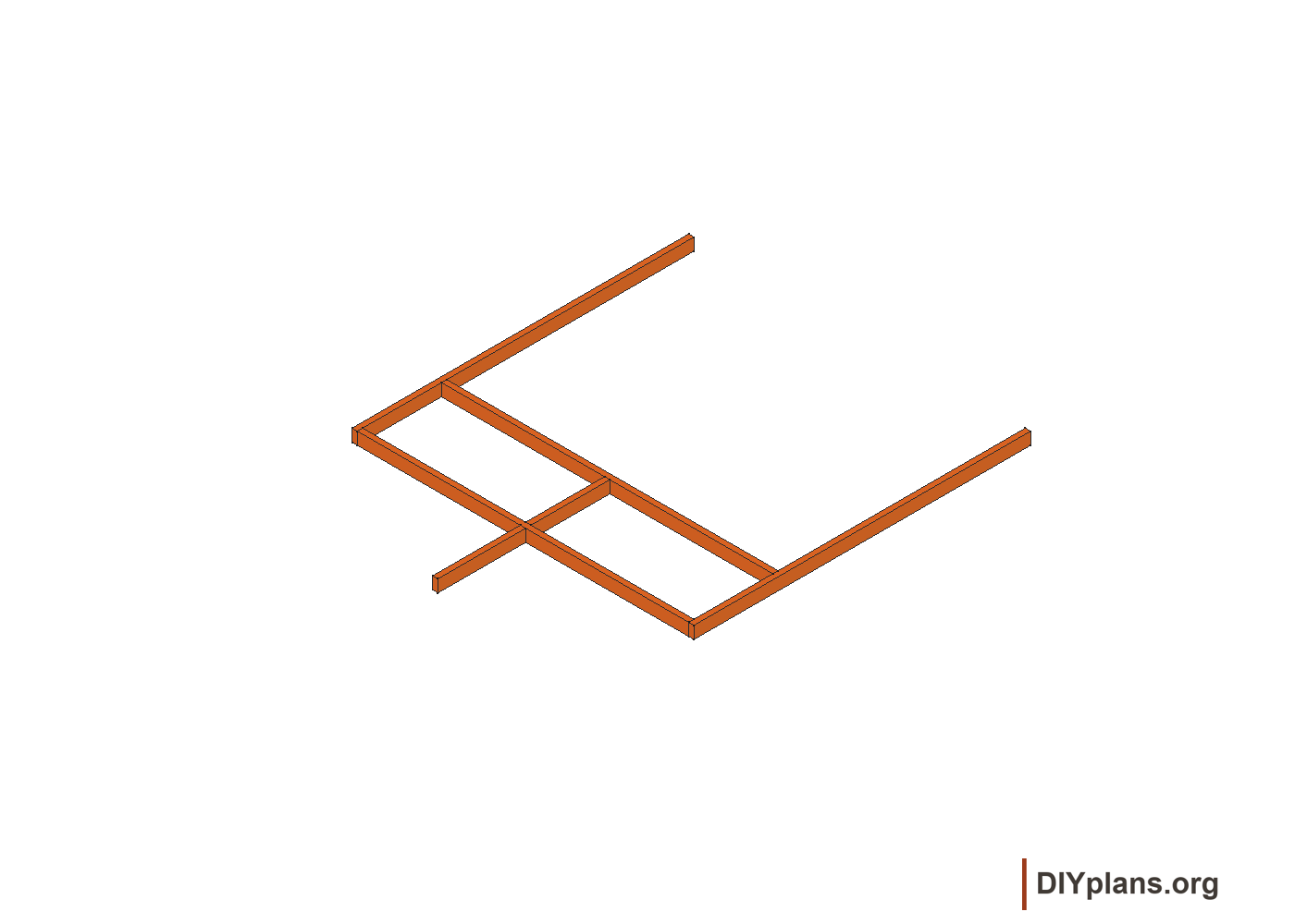
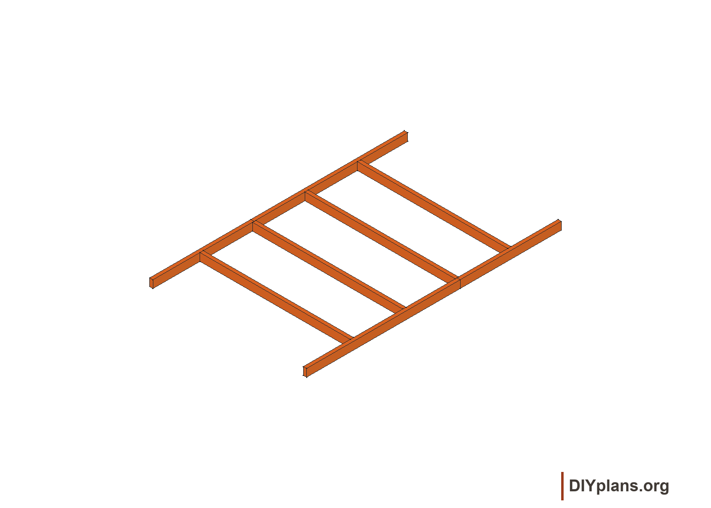
- Place the two 116-5/8 rim members parallel. Place the 117-inch members between them so the overall footprint becomes 120 x 116-5/8.
- Mark matching joist centerlines on the two rims at 16, 32, 48, 64, 80, 96 and 106 inches from the same end reference. Fit the end crossmembers flush at the two ends, with the last interior centerline 10⅝ inches from the far end.
- Keep both frame ends flush and square at the corners.
- If using the two optional joists, divide the intermediate bays to approximately 12-inch spacing while preserving all panel-edge support.
Check: Frame measures 120 × 116⅝ inches and supports all panel seams.
12 Nail the floor frame
- 36 hot-dipped galvanized 10d 3-inch nails, hammer/nailer, square.
- Keep members flat and on their marks.
- Drive two 3-inch nails through the rim into each joist end at every marked connection.
- Add the eight specified nails for the optional reinforcement if installed.
Check: Each joist end has two nails; ends remain flush.
13 Level and square the frame
- level, tape, runners/leveling supports.
- Set the frame on the leveled runners.
- Check level along both axes and diagonally across the frame.
- Measure corner to corner both ways; adjust until the two diagonal measurements are equal. The expected diagonal is about 167-3/8.
Check: Frame is level and both diagonals match at about 167⅜ inches.
14 Lock the frame to the runners
- at least 54 exterior 3-inch treated-lumber-compatible screws, drill.
- At one side of the frame, place one fastener at the end contact point of each runner.
- Move to the opposite side and place one fastener at each runner end while preserving square.
- Recheck diagonals.
- Secure every frame-to-runner contact with two angled 3-inch structural screws. Nine crossmembers crossing three runners produce 27 contacts and require 54 screws. Count the actual contacts and include the initial positioning screws in the final two-per-contact pattern.
Check: Every runner contact has two screws; diagonals remain equal.
15 Use the first floor sheet to re-square
- one full 5/8 x 48 x 96 OSB sheet, four 2-inch floor nails initially, tape.
- Place the rough/grid side up.
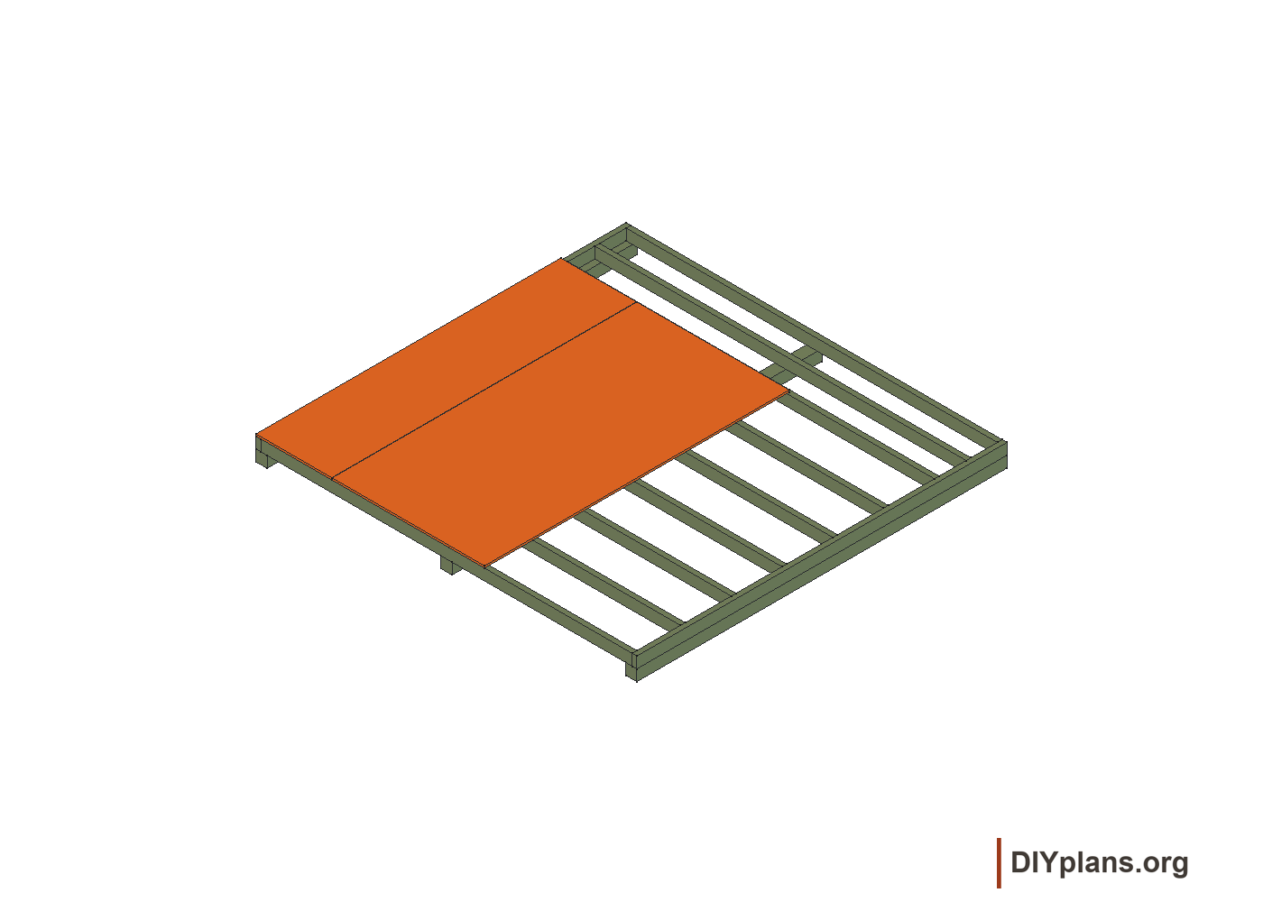
- Start at a floor corner. Align a 48-inch sheet edge with the outside frame edge, with the 96-inch direction crossing the joists. The opposite 48-inch edge ends at the 96-inch joist centerline so it has ¾ inch of bearing and leaves the other half of that joist for the adjacent panel.
- Drive two 2-inch nails at the first two corners.
- At the opposite end, use the long sheet edge as a lever until the top corner is flush; drive two corner nails.
- Recheck equal diagonals, about 167-3/8.
Check: Panel edges align with the frame and the two diagonals match.
16 Finish nailing the first floor sheet
- 2-inch hot-dipped galvanized floor nails, chalk line or printed grid.
- Mark joist centers with a chalk line if the printed grid does not expose them clearly.
- Nail every supported sheet edge at 6 inches on center.
- Nail the sheet field into joists at 12 inches on center.
Check: Nails enter framing at 6-inch edges and 12-inch field spacing.
17 Cut and install the remaining floor deck
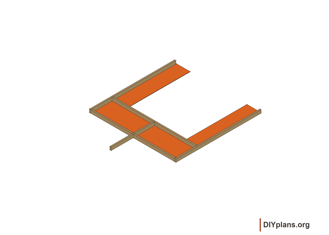
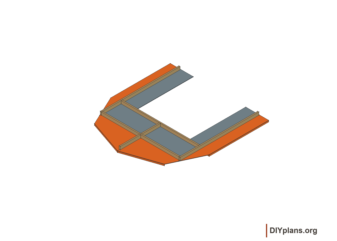
- second full 48 x 96 sheet; 23-7/8 x 96, 20-5/8 x 96, and 20-5/8 x 23-7/8 pieces; enough floor nails to reach at least 182.
- Make the four-sheet cuts in the Cut list.
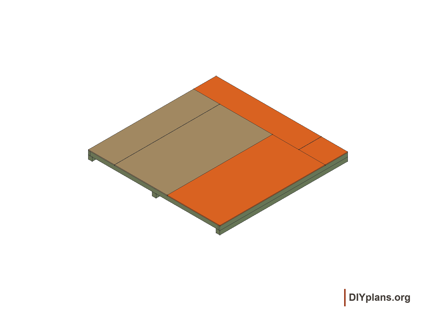
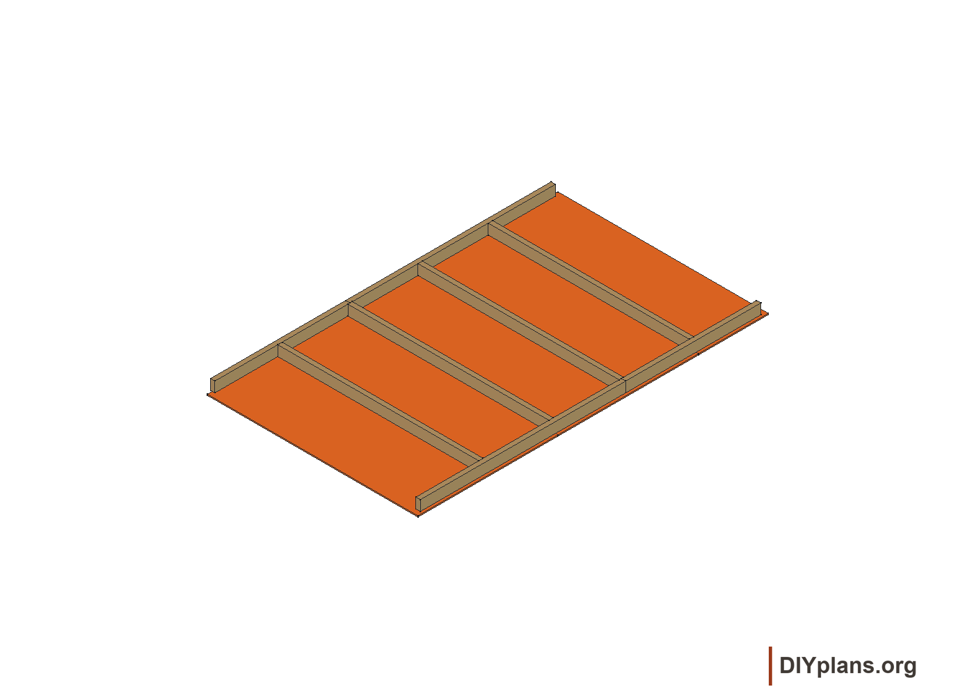
- Beside the first full sheet, install the second 48 × 96-inch sheet, then the 23⅞ × 96-inch strip. At the remaining 20⅝-inch-wide end of the floor, place the 20⅝ × 96-inch strip and the 20⅝ × 23⅞-inch corner piece. Keep the long sheet directions and seam supports consistent with the floor layout.
- Keep exterior edges flush and seams on framing. Use the panel product’s required expansion gaps; verify actual sheet dimensions and trim fit without removing required edge bearing.
- Nail supported edges every 6 inches and fields every 12 inches with 2-inch nails. Have at least 182 nails available, with spares; the spacing pattern controls the completed count.
Check: Deck edges are flush, seams supported and nail heads seated.
18 Re-level and organize wall work
- level, wall-part groups.
- Check the completed floor in both directions and re-level beneath runners if necessary.
- Use the floor as the flat assembly table.
- Stage back-wall, front-wall, and the two side-wall groups around the deck so completed walls need minimal handling.
Check: The floor remains level and provides a flat assembly surface.
19 Build the first half of the back-wall frame
- NK 48, one PR 94-1/2, two PT 96, six 3-inch nails.
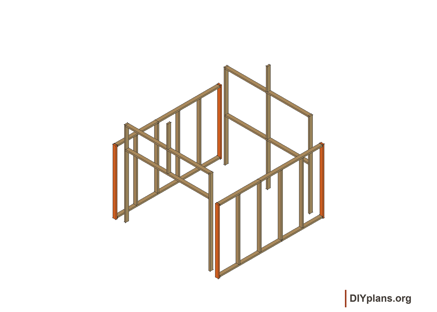
- Lay the two PT end posts parallel, standing on their 1½-inch edges so the wall is 3½ inches deep. Place the 94½-inch PR rail between them; outside-to-outside frame width is 97½ inches.
- Use the 48″ NK temporarily as a gauge against each PT, with its lower end flush to the PT lower end. Locate the underside of PR 48″ above both PT lower ends. Do not nail NK while using it as the gauge.
- Move NK to the center under PR, with its centerline 48¾ inches from either outside edge of the frame. Keep the 1½-inch-wide member faces and their edges aligned.
- Drive two 3-inch nails at each of the three final connections: PR to each PT and centered NK to PR.
Check: Back frame is 97½ inches wide; lower rail underside is 48 inches above the post bottoms.
20 Complete the back-wall frame
- NC 45, second PR 94-1/2, six 3-inch nails, two 3-inch screws.
- Place the second PR between the PT posts with its upper face flush with the post tops, 96 inches above their lower ends.
- Center the 45-inch NC between the two PR rails, 48¾ inches from either outside frame edge. Its upper end meets the underside of the upper PR and its lower end meets the top of the lower PR.
- Drive two 3-inch nails at each PR-to-PT end connection and two 3-inch nails through the upper PR into NC: six nails total. Drive two 3-inch screws through NC at its lower middle connection.
Check: Upper rail is flush with 96-inch post tops; the lower NC joint has two screws.
21 Square and nail the first back panel
- One ⅜ × 48 × 96-inch wall panel, GAA ¾-inch gauge, 44 two-inch nails and temporary 2 × 4 supports.
- Support the frame level. Place the first panel primed face up, with the square edge outside and the meeting lap at the centerline.
- Use GAA to set the outer panel edge ¾ inch inward from the outside frame edge. Set the panel top ¾ inch below the frame top; the 96-inch-tall panel then extends ¾ inch below the frame bottom.
- Nail panel edges every 6 inches and the field every 12 inches with 2-inch nails, keeping nails out of siding grooves.
Check: Panel top is ¾ inch below the frame; its bottom extends ¾ inch below.
22 Add the second back panel
- second 3/8 x 48 x 96 panel, gauge, 44 2-inch nails.
- Set the second panel primed face up. Fit its mating lap to the first panel without forcing the groove or changing the outside frame width.
- Maintain the ¾-inch outside reveals on the 97½-inch-wide frame. Match the two panels’ top and bottom edges.
- Nail edges every 6 inches and fields every 12 inches; angle seam nails only as needed to draw the joint tight, while staying out of the groove.
Check: Both panels align at their seam, top and bottom edges.
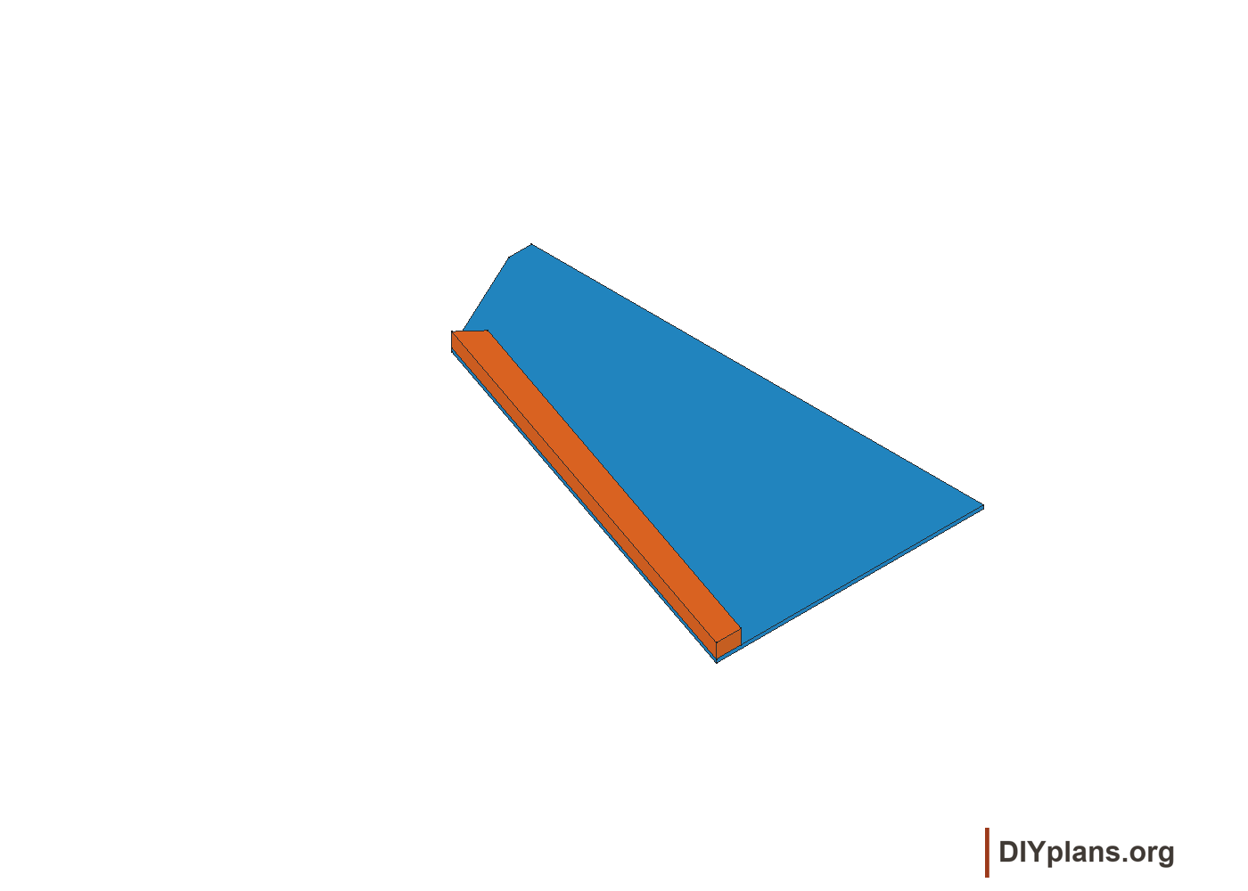
23 Assemble the four wing panels and corner studs
- Two left and two right wing panels, four 2 × 4 × 72⅝-inch corner studs (OB), 32 one-and-a-quarter-inch screws and 2 × 4 supports.
- Retrieve the four square-ended corner studs (OB) from S04. Check their 72⅝-inch length and label the four corners, with the best exposed face outward.
- Match each stud to its left- or right-handed wing panel from S06.
- Lay OB flat and support the panel primed face down on its 3½-inch-wide face. The stud’s 1½-inch thickness projects outside the siding.
- Align the panel’s square bottom and outer long edge with OB. The stud face extends inward from the outside corner edge.
- Attach each pair with eight 1¼-inch screws approximately 10 inches apart. Keep screws centered over the stud and their tips below its exposed face.
- Make two left and two right assemblies; reserve one pair for the front wall.
Check: Two left and two right wing assemblies are complete, with no exposed screw tips.
24 Attach the back wing walls
- one left and one right wing assembly, 34 2-inch nails.
- Place both assemblies primed face up on the back frame with their tops flush.
- Fit the inner panel joints tight; angle nails where needed to close seams.
- Nail each assembly to the frame at 6-inch spacing with 2-inch nails, avoiding siding grooves.
Check: Wing tops align and seams close without gaps.
25 Assemble the four gable panels and upper end rafters
- Two left and two right gable panels, four 2 × 3 × 45⅛-inch upper end rafters (PD) and 24 one-and-a-quarter-inch screws.
- Cut four upper end rafters (PD), actual 1½ × 2½ inches, to the resolved angled-end profile. Their finished length is 45⅛ inches; confirm the long/short-point convention and mark each peak end red.
- Match each member to a left or right gable panel from S06.
- Lay PD flat with the panel primed face down over it and its red end at the peak.
- Align PD with the panel’s sloping top and peak edges.
- Attach each pair with six 1¼-inch screws approximately 11 inches apart.
- Make two left and two right assemblies; reserve one pair for the front.
Check: Two left and two right gable assemblies have marked peak ends.
26 Complete the back-wall gable
- One CO 2 × 4 × 25-inch post, a left/right gable pair, two three-inch screws and 24 two-inch nails.
- Stand CO on edge at the center of the upper PR, with its centerline 48¾ inches from either outside frame edge and its 1½-inch width centered on that line. Align its 3½-inch depth with the frame and attach it with two 3-inch screws.
- Put the left gable assembly primed face up on the wall and CO. Align its seam edge with the right edge of the 3/8-inch siding groove; nail every 6 inches with 2-inch nails.
- Put the right gable assembly primed face up, flush to the left assembly and CO; nail every 6 inches.
- Carefully flip or move the completed wall off the floor with helpers.
Check: Gable halves meet flush over the center post.
27 Build the front-wall frame
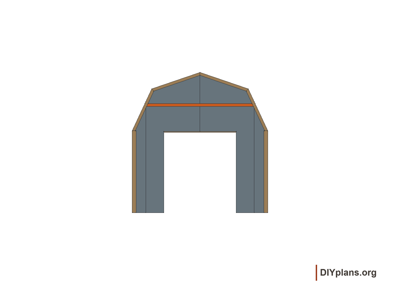
- One LV 22½ inches, two PR 94½ inches, two PT 96 inches, all 2 × 4; twelve three-inch nails.
- Place PR, PT and LV on their 1½-inch edges so the frame is 3½ inches deep. Put both PR rails between the PT end posts.
- Set the upper PR flush with the post tops and fasten it with two 3-inch nails at each end.
- Use LV as a 22½-inch clear spacer between the two PR rails, placing the lower rail with its underside 70½ inches above the PT lower ends. Attach that lower PR with two 3-inch nails at each end.
- Center LV between the rails, 48¾ inches from either outside frame edge. Fasten it with two 3-inch nails through each rail, four total.
Check: Front frame is 97½ inches wide with a centered header stud.
28 Install the left front panel
- Left front panel, spacer gauge (GAA) and 36 two-inch nails.
- Place the left front panel primed face up, with its tall outside edge at the left PT post and its opening cutout facing the center of the wall.
- Use GAA to set the ¾-inch outside, top and opening-edge reveals. Check the door opening before fastening.
- Nail the panel to framing every 6 inches with 2-inch nails, avoiding grooves.
Check: Panel reveals measure ¾ inch; the opening matches the door design.
29 Install the right front panel
- Right front panel, spacer gauge and 36 two-inch nails.
- Set the right panel primed face up and flush to the left panel at the center seam.
- Maintain the matching ¾-inch outside, top and opening reveals on the 97½-inch-wide frame. Confirm the opening matches the finalized door design.
- Nail every 6 inches with 2-inch nails; angle seam nails only enough to close the joint and keep nails out of grooves.
Check: Front panels meet flush and the opening is square.
30 Attach the front wing walls
- reserved left/right wing assemblies, 34 2-inch nails.
- Place both assemblies primed face up on the front frame with their tops flush.
- Close the seams and nail through the panel into framing every 6 inches with 2-inch nails.
- Avoid siding grooves and use angled nails only to draw seams tight.
Check: Front wing tops align and panel joints are tight.
31 Complete the front-wall gable
- Second CO 2 × 4 × 25-inch post, reserved gable pair, two three-inch screws and 24 two-inch nails.
- Center CO on edge at the top, 48-3/4 to each side, and attach it with two 3-inch screws.
- Install the left gable primed face up; align its seam edge with the right edge of the 3/8-inch groove and nail every 6 inches.
- Install the right gable flush to the left and nail every 6 inches.
- Move the completed front wall off the deck with helpers.
Check: Front and back gable profiles match.
32 Build both side-wall frames
- Four NH 46¼ inches, eight OU 68¾ inches and four OZ 70¼ inches, all 2 × 4; three-inch nails, tape and square.
- For each side wall, lay out two NH plates, two OZ plates and four OU studs on their 1½-inch edges. The wall depth is 3½ inches.
- Join one 70¼-inch OZ and one 46¼-inch NH to form each 116½-inch plate. Reverse their order on the opposite plate so the two seams are staggered.
- Measure from the same end of both plates and mark OU stud centerlines at 22¼, 46¼, 70¼ and 94¼ inches. Mark each stud’s 1½-inch width, ¾ inch to each side of its centerline.
- Place the 68¾-inch studs between the plates. Overall frame height is 71¾ inches, including both 1½-inch-thick plates.
- Drive two 3-inch nails at each stud end and two at each plate splice. Confirm the splice toenailing angle and edge distances from the connection detail before fastening.
- Repeat for the second wall, using at least 20 nails per frame for this pattern.
Check: Both frames measure 116½ × 71¾ inches with staggered plate splices.
33 Square each side frame with its first panel
- one 3/8 x 48 x 72 panel per wall, gauge, 2-inch nails.
- Place the first 48 × 72-inch panel on a side frame, primed face up, with its exterior square edge at the wall end and its mating lap toward the next panel.
- Keep the panel top ⅝ inch below the frame top, leaving its lower edge ⅞ inch below the bottom plate. Use GAA to maintain ¾ inch of panel bearing at the stud centerline.
- Pin the first end with two 2-inch corner nails.
- Use the long panel edge to rack the frame until the opposite end also measures 3/4; pin it with two corner nails.
- Nail edges every 6 inches and the field every 12 inches, never in the groove.
- Repeat this squaring procedure on the second frame. Allow 34 nails for each first panel, then follow the 6-inch edge and 12-inch field spacing on both.
Check: Both frames are square, with ⅝-inch top setbacks and ¾-inch stud bearing.
34 Finish both side-wall panels
- Two additional ⅜ × 48 × 72-inch panels, two ⅜ × 23⅞ × 72-inch panels, GAA gauge and 166 two-inch nails allowance.
- On each wall, fit the second 48-inch panel primed face up to the first panel’s lap. Match its top and bottom edges, retaining the ⅝-inch top setback and ¾-inch stud bearing.
- Nail its edges every 6 inches and field every 12 inches; angle seam nails as needed to close the joint.
- Add the 23⅞-inch panel at the remaining end, square edge outside and lap joined to the previous panel. Nail supported edges every 6 inches.
- Maintain a continuous ⅝-inch panel-top setback below the frame and ⅞-inch siding extension below the bottom plate.
- Carefully flip the first wall and repeat all panel steps for the second.
Check: Panel tops are ⅝ inch below framing; bottoms extend ⅞ inch below.
35 Stand and brace the back wall
- Completed back wall, one KP 96-inch temporary brace, eight three-inch screws (two brace and six frame screws), 24 two-inch nails.
- With helpers, center the back wall on the 120-inch floor dimension.
- Temporarily brace it with KP and two 3-inch screws.
- First nail the lower panel edge into the floor frame every 6 inches with 2-inch nails, angled to enter framing and kept out of siding grooves.
- Drive two 3-inch screws through the bottom of each PT end post and through the NK center upright into the floor structure. Keep the wall braced and verify that every angled screw enters framing.
Check: Back wall is centered, braced and attached to floor framing.
36 Stand and attach both side walls
- two side walls, 70 2-inch nails, twenty 3-inch nails, four 3-inch screws.
- Stand the right wall, center its 116½-inch frame on the 116⅝-inch floor depth and leave 1/16 inch at each frame end.
- Pin the side panel to the back OB corner stud with one 2-inch nail at the lower corner.
- Keep the outside panel edge aligned consistently along the full height of OB; pin the upper corner with one 2-inch nail.
- Nail that vertical edge into OB every 6 inches with 2-inch nails.
- Nail the bottom panel edge every 6 inches, angling into the floor frame.
- Drive two 3-inch nails through the bottom plate into floor framing in each open bay, including the two end bays.
- Drive one 3-inch screw through the back OB corner stud into the side-wall top plate and one into its bottom plate. OB is structural framing, actual 1½ × 3½ inches.
- Remove/reposition the temporary brace only after the corner can support itself.
- Repeat the full order for the left side wall.
Check: Side frames leave 1/16 inch at each floor end; corners remain plumb.
37 Stand and attach the front wall
- completed front wall, 38 2-inch nails, eight 3-inch screws.
- Stand the front wall and center it side-to-side.
- First nail its lower panel edge flush to the floor every 6 inches with angled 2-inch nails into the floor frame.
- Pin a lower side-wall corner to the front OB corner stud with one 2-inch nail.
- Keep the outside panel-edge alignment on OB equal over the full height. Pin the upper corner, then nail the vertical edge every 6 inches.
- Drive two 3-inch screws through the bottom of the front PT end post into the floor framing.
- Drive one 3-inch screw through front OB into the adjoining top plate and one into the bottom plate.
- Repeat the PT-to-floor and OB-to-side-wall connections at the other front corner, using eight 3-inch screws total.
Check: Walls are plumb, corners aligned and the door opening square.
38 Install the lower end rafters
- Four 2 × 3 × 41-inch lower end rafters (PF) and 24 one-and-a-quarter-inch screws.
- Fit one PF along each front lower gable slope, with its upper end contacting PD and its lower end contacting OB. Do not notch or rebate OB or PF.
- From the panel side, drive six 1-1/4-inch screws into each PF at about 7-1/2-inch spacing.
- Repeat on the back gable with the remaining two PF.
Check: Each lower end rafter contacts both adjoining members.
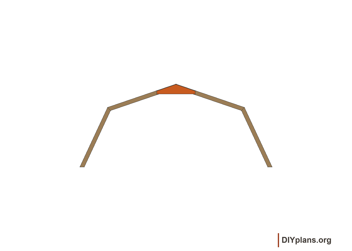
39 Build the rafter halves and peak gussets
- Rafter lumber, connector and gusset stock; saw, layout tools, clamps and specified fasteners.
- Resolve the rafter fabrication drawing before cutting: structural section and grade, segment lengths, base/peak/knee cuts, connector profiles and faces, fasteners and adhesive.
- Cut and label 16 segments for eight two-segment halves, making mirrored pairs. Use the approved joint drawings; roof pitch alone does not define the cuts.
- Build eight knee-connected halves flat in the assembly jig. Install the specified connectors, glue and fasteners, then mark the peak ends red.
- Cut eight peak gussets to their resolved structural material, thickness and outline. Each fits within 6 × 24 inches.
- Dry-fit a pair across the 120-inch jig span. Both bases must seat at the wall positions and the peak ends must meet.
Check: Eight knee-connected halves and eight gussets match the completed fabrication drawings.
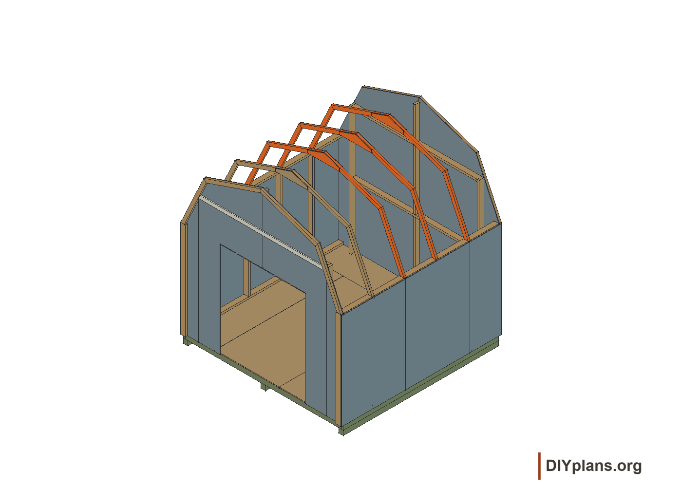
40 Build four rafter assemblies
- eight rafter halves, eight gussets, exterior glue, 96 2-inch nails, temporary OO support if useful.
- Set a flat jig across the 120-inch outside wall width. Place two halves at their bearing positions on the 3½-inch-deep plates.
- Bring the two red ends together at the peak.
- Spread exterior glue where the first gusset bears.
- Center the first gusset with its sloping upper edges ¼ inch below the rafter edges. Attach it with twelve 2-inch nails in the completed peak-joint pattern; resolve that pattern before fastening.
- Flip the assembly, glue the second face, and attach the second gusset with twelve more 2-inch nails.
- Repeat to make four assemblies.
Check: Each peak has two glued gussets and 24 nails.
41 Install all four rafters
- four assemblies, sixteen 3-inch screws, tape, pencil.
- Set rafters centered over the side-wall stud marks so load transfers directly to studs.
- From the inside face of each end panel, locate the nearest rafter center 22-1/4 in; keep the three interior rafter-center spaces at 24.
- Keep each rafter base flush/centered at its mark.
- Angle two 3-inch screws through each rafter end into the wall framing, sixteen total.
Check: Rafters sit over studs at 24-inch centers, with 22¼ inches to the inside end-panel faces.
42 Install the rear loft ledgers
- Two 59¾-inch rear ledgers (SU), eight three-inch nails and level.
- Place the two SU ledgers against the back frame’s interior face, one from each side toward the center. Their rear faces sit 3½ inches forward of the outside back-frame plane.
- Measured from the front floor edge, the ledgers occupy 111⅝ to 113⅛ inches.
- Set their bottoms level with the wall-plate tops at 71¾ inches above the floor. Their top bearing surfaces are 75¼ inches high. Leave ¼ inch at each outside ledger end.
- Drive two 3-inch nails at each attachment to the back frame, eight total.
Check: Ledger bottoms are level at 71¾ inches; top bearing surfaces are at 75¼ inches.
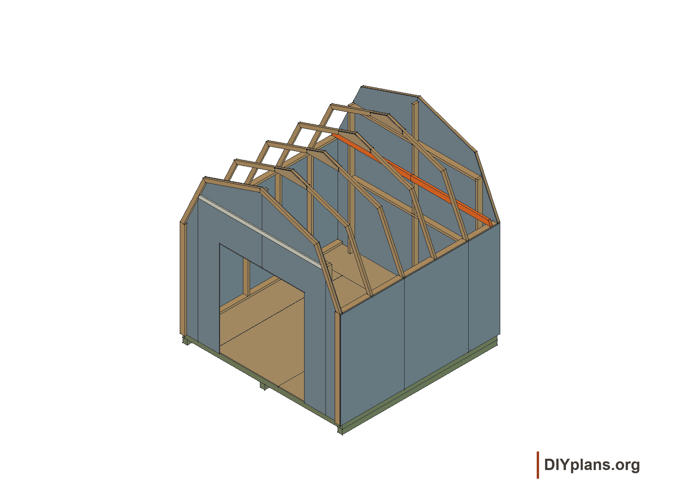
43 Build four loft-beam half assemblies
- Four 92⁵⁄₁₆-inch long plies (JRA), four 28¾-inch short plies (HHP), glue and 24 three-inch nails.
- Glue the broad face of each short ply (HHP) against the end region of a long ply (JRA), with their grain parallel.
- Align the angled ends flush. Resolve the end profiles, overlap and six-nail layout before assembly; the layout includes 1½-inch and 5½-inch references.
- Drive six 3-inch nails in the staggered pattern.
- Repeat to make four half assemblies.
Check: Four glued half assemblies each have six nails and flush angled ends.
44 Laminate two full loft beams
- four half assemblies, glue, 22 3-inch nails.
- Pair the halves with parallel grain, reversing one end-for-end. The short reinforcement then lies at opposite ends in the two plies, staggering their joints.
- Glue the mating faces, clamp the ends flush and check the finished 119¾-inch length.
- Drive eleven 3-inch nails in the completed two-row alternating pattern. Keep 1½ inches between rows and the 3-inch end/joint and 7¾-inch station references. These references require a complete layout before fastening.
- Repeat for the second beam.
Check: Both beams measure 119¾ inches and remain straight.
45 Install the loft beams
- Two built-up loft beams, eight three-inch screws and tape.
- Put one joist flush against the front face of each of the two rear rafters.
- At each end, first angle one 3-inch screw through joist into top plate.
- Then drive one 3-inch screw through rafter into joist.
- Recheck the two 24-inch rafter spaces after fastening.
Check: All eight screws are installed; rafters remain 24 inches on center.
46 Temporarily fasten the loft panel
- 7/16 x 48 x 96 loft panel, exactly four 2-inch nails.
- Lay the 48 × 96-inch loft panel grid side up across the ledgers and beams, centered across the shed. Its underside sits 75¼ inches above the floor.
- Butt the rear edge to the back frame’s interior face, 3½ inches forward of its outside plane. Measured from the front floor edge, the panel runs from 65⅛ to 113⅛ inches.
- Check the 1⁷⁄₁₆-inch front overhang against the approved loft drawing. Confirm the panel connections and allowable storage load.
- Drive only four 2-inch nails now so the roof can still be squared. Keep the loft unloaded during roof work.
Check: Panel is centered, rear edge against the frame, and held by only four nails.
47 Rack the roof with the first panel
- one 7/16 x 45-1/8 x 96 roof panel, GAA gauge, four initial 2-inch nails, helpers/ladders.
- Treat loose roof panels as a falling/injury hazard until secured.
- Put the panel rough/grid side up on the first roof plane, flush at the peak, with 3/4-inch bearing/reveal on the rafter.
- Pin two corners with 2-inch nails.
- At the opposite end, move the long panel edge sideways until its upper corner is flush at the peak. Set the panel end edge ¼ inch inward from the outer edge of the structural end-rafter member at the gable. This is a setback on the supporting member, not an unsupported gap.
- Move the back wall slightly if necessary to achieve that 1/4-inch end setback, then pin the other two corners.
Check: Roof peak is flush; panel has ¾-inch rafter bearing and ¼-inch gable-end setback.
48 Install the rest of the roof deck
- Remaining seven roof panels, 196 two-inch nails total allowance for all eight panels, tape and GAA gauge.
- At the first panel's lower edge, hold each end rafter center 22-1/4 from the inside end-panel face and the three interior center-to-center spaces at 24; place one 2-inch nail into each rafter.
- Repeat that center check and one-nail-per-rafter tack at the top.
- Finish the panel with 2-inch nails every 6 inches on edges and 12 inches in the field.
- Fit the 23-7/8 x 45-1/8 upper panel flush to the first, flush at peak, and with the 1/4-inch end setback relative to the outer gable-trim edge; nail at the same 6/12 pattern.
- Fit the 41-7/8 x 96 lower panel and its 23-7/8 x 41-7/8 mate flush to the upper panels, holding 3/4 at the rafter and the same 1/4-inch gable-end setback; nail 6 inches on edges and 12 inches in fields.
- Repeat the complete process on the opposite roof plane.
Check: All eight roof panels are secured at 6-inch edges and 12-inch field spacing.
49 Finish the loft panel fastening
- eleven 2-inch nails.
- After squaring and sheathing the roof, check the centered loft panel’s rear edge against the back frame. It must bear on the rear ledgers and both beams.
- Add eleven 2-inch nails at 24-inch spacing into the supports, following the panel fastening pattern.
Check: Loft panel is secured to both beams and the rear ledgers.
50 Couple and align the doors on temporary supports
- Completed doors and hinge boards, two ⅜-inch meeting-gap spacers, two collar ties (KP), four 1¼-inch screws and four 2-inch screws.
- On a flat surface, place both doors exterior-face up, with the left hinge board marked green and the right marked red. Each hinge board extends ⅜ inch above its door leaf.
- Align the door bottoms and place the two spacers between the leaves to hold the ⅜-inch meeting gap.
- Bridge the doors with the two temporary KP supports.
- At each support, drive 1¼-inch screws in the middle and 2-inch screws at the ends, four of each total.
Check: Door bottoms align and spacers hold a ⅜-inch meeting gap.
51 Hang the doors
- One 69-inch door weatherstrip (OO), seven three-inch screws, paired doors and helpers.
- Fasten OO horizontally as a temporary ledger directly beneath and flush to the wall panels with three 3-inch screws.
- Rest the coupled doors on the ledger. Align the center of their ⅜-inch meeting gap with the right edge of the center siding groove, then check the full opening and both hinge-board bearing surfaces.
- At each hinge board, drive one 3-inch screw into the upper structural support and one into the floor framing, four total. Angle the lower screws into the floor frame and follow the door drawing’s mounting positions.
- Remove OO and both KP temporary supports, then operate both doors.
Check: Both doors swing freely and hinge screws enter framing.
52 Reinforce doors and install ZJ head trim
- ZJ 5/8 x 3 x 72, fifty 3/4-inch screws, eight 2-inch finish nails.
- From inside, attach each hinge board with six ¾-inch screws approximately 14 inches apart vertically, following the door fastening pattern.
- Drive the remaining ¾-inch screws through panels into trim centers, with two at each trim seam. Use 50 total for hinge boards and trim; keep tips below exposed faces.
- Center the 72-inch door header trim (ZJ) above the opening.
- Attach ZJ with eight 2-inch finish nails into framing along its length. Keep nails away from trim ends.
Check: Trim seams have paired screws; header trim is centered.
53 Install the OO door weatherstrips
- Two 69-inch door weatherstrips (OO) and fourteen two-inch screws.
- Close the left door. Center one OO vertically along the meeting edge, projecting 1 inch past the trim toward the right leaf.
- Drive seven 2-inch screws through exterior trim into OO in the door fastening pattern.
- Close the right door. Center its OO vertically and set it 1 inch inward from the meeting trim edge, away from the left leaf.
- Attach it with seven 2-inch screws. Keep screw tips below exposed faces and check that both doors close.
Check: Weatherstrips have the opposing 1-inch projection and inset; doors close without binding.
54 Install barrel bolt and hasp
- barrel bolt plus four 3/4-inch screws; hasp/latch plus seven 3/4-inch screws; 3/8-inch drill bit; hammer.
- Mount the barrel bolt flush at the top of OO on the left door with its four screws.
- Close the door, extend the bolt, and tap it lightly to mark the receiving-hole center.
- Drill a 3/8-inch hole in line with the bolt, only deep enough for full bolt travel.
- Put the hasp on the right door and latch on the left. Set the hasp's bottom edge 35-1/2 above the bottom edge of door trim.
- Mark and attach both pieces with the seven supplied screws.
Check: Bolt enters freely and the hasp sits 35½ inches above the trim bottom.
55 Install collar ties
- two KP 1 x 4 x 96, twelve 2-inch nails, level.
- Install one KP across each of the two rafter pairs closest to the door opening, preferably on the back side of rafters for appearance.
- Hold each tie level and flush to the underside of the roof panels at both ends.
- Drive three 2-inch nails through each end into the rafter, six per tie.
Check: Ties are level, with three nails at each end.
56 Install horizontal gable seam trim
- Two 1 × 3 × 94½-inch gable seam trims (HQ), twenty two-inch finish nails and level.
- Fit one angled-end HQ over the front horizontal panel seam. Center and level it between the lower end rafters (PF), without notching PF.
- Fasten it into framing with ten 2-inch finish nails along its length.
- Repeat at the back with the second HQ.
Check: Seam trims are level and meet the end rafters without notches.
57 Caulk, prime, and paint
- three tubes paintable acrylic-latex caulk, caulk gun, primer, specified paint, brushes/rollers.
- Caulk every horizontal and vertical exterior seam, every trim-to-wall joint, and the full perimeter of door trim.
- Prime every unprimed exterior wood face/edge according to primer directions.
- Paint siding with high-quality 100 percent acrylic-latex exterior paint; apply the recommended two coats.
- Paint trim with the specified exterior paint.
- Deliberately coat the bottom edge of every siding/trim piece, plus the inside face and all four edges of both doors.
- Let finish products cure for the specified time before roofing contact or repeated door use.
Check: All exposed faces, edges and end grain are coated.
58 Install roof felt and drip edge
- Underlayment allowance of 145 square feet; about ¼ lb of suitable felt fasteners; 30 feet of gable drip edge plus any required eave pieces; tin snips.
- Choose a roofing system suitable for both shed slopes and the gambrel bend. Confirm underlayment, flashing, fasteners, overlaps and exposure before installing the roof covering.
- Where compatible with that system, cover both roof planes with underlayment, overlapping felt courses by 3 inches and covering the ridge. Use the selected product’s greater lap where required.
- Use only enough compatible underlayment fasteners to hold the material flat until the roof covering is installed. Confirm whether 1-inch nails provide the required penetration.
- Install the front and back gable drip edge, plus the eave flashing required by the complete roofing design. Follow the selected system’s sequence for flashing above or below underlayment.
- Nail the horizontal top flange; keep nails out of the exposed vertical face.
- Keep the flashing aligned with the trim. Snip and bend at the gambrel transition only when that treatment is allowed by the chosen flashing system; otherwise use its specified transition detail.
Check: Underlayment laps and flashing follow the selected roofing system.
59 Install 3-tab shingles on both roof planes
- six bundles 3-tab shingles, 3 pounds 1-inch roofing nails, chalk line, hooked blade, ladder, safety gear.
- Confirm this course layout and fastening against the selected shingle product before starting. The layout uses four nails per field shingle: outer nails 1 inch from the ends and inner nails ½ inch to the corresponding side of the rain-slot lines. Keep field nails below the sealing strip. Use a different pattern wherever required by the selected product, roof slope or wind design.
- At the back/bottom eave of the first roof plane, install the starter course upside down, colored face up, straight and level. Use four nails per shingle and project it 1 inch beyond the back and lower roof-deck edges; if drip edge is present, run shingles flush to it instead.
- Starting at the front, install the first exposed course flush to the starter-course bottom. Put its leading notch 1 inch past the roof edge, or flush to drip edge.
- Install the second course with its bottom edge aligned at the tops of the first course's rain slots. Maintain the 1-inch front overhang or drip-edge flush and stagger the course at the front.
- Continue upward, maintaining the stagger.
- At the roof-slope bend, ensure the shingle spanning the bend extends 3 to 4 inches down the lower pitch and its rain slot sits above the bend. If a normal course leaves the slot below the bend, overlap the rain slot until both conditions are met.
- Fasten the bend overlap with two roofing nails per tab.
- Continue to the ridge. The distance from ridge to top of the last rain slot must be 5 inches or less; if greater, add another course. Cut any ridge overlap flush to the peak.
- Repeat the full starter/course/bend/ridge process on the second roof plane.
- At both gable ends, snap a chalk line 1 inch beyond the roof-deck edge and cut shingle ends straight with a hooked blade. Where the selected drip-edge detail calls for flush shingles, follow that edge instead.
Check: Courses are staggered, bend details are secure and gable cuts are straight.
60 Make and install the ridge cap
- approximately 24-26 cap pieces cut from 3-tab shingles, roofing nails, utility knife.
- Use a cap detail approved for the selected shingles. For compatible 3-tab shingles, cut each into three caps and taper the upper sides about 2 inches inward at the tab shoulders. Use sound, full-sized offcuts where suitable.
- At the front, place the first cap flush to the field shingles. Drive one nail per side through the weather-seal area.
- Place the second cap 5 inches back from the first, flush across the ridge; again use one nail per side through the seal.
- Continue toward the back at 5-inch exposure.
- At the last full cap, ensure at least 4 inches of colored shingle remains between the visible color boundary and the field-shingle edge; trim the cap flush to the field shingles.
- Cut a final cap at the top of its rain slot and place it flush over the back end.
- Secure the final cap with two nails per side.
Check: Caps cover the ridge, with 5-inch exposure and four nails in the final cap.