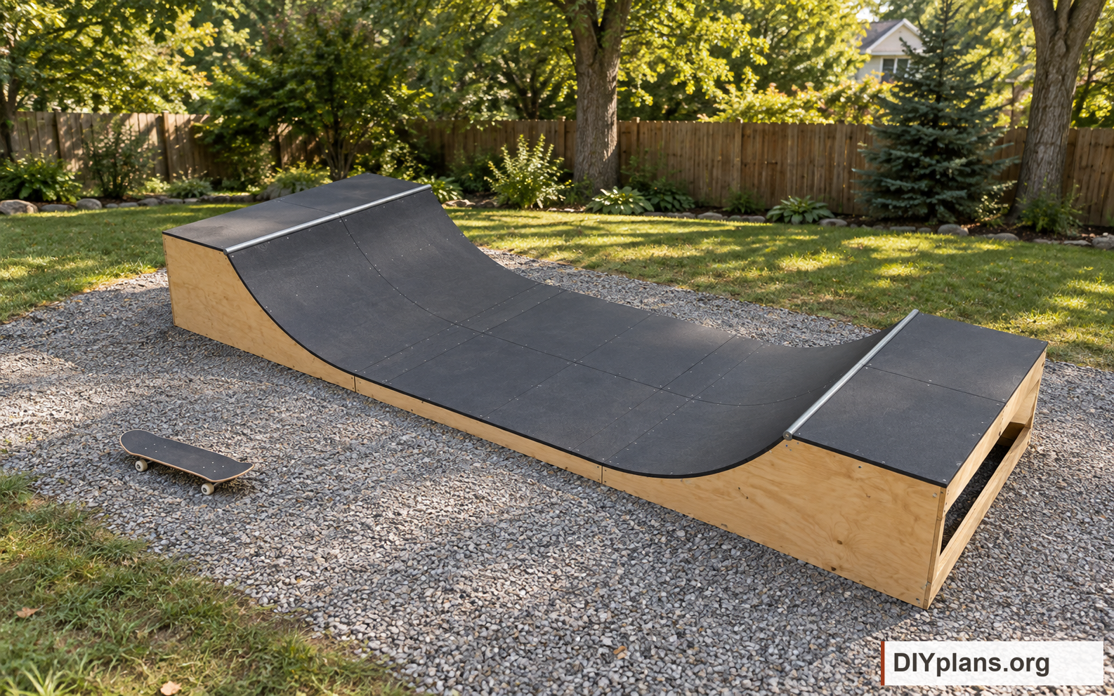
Before you start
- Choose a level concrete slab, leveled concrete pavers, or a firm, compacted crushed-gravel base. Support every bottom edge of all three modules continuously. Arrange drainage, anchorage, deck access, guards and site clearances for the location before assembly.
- Measurements in the guide, drawings and cut list are rounded to the nearest 1/16 inch. Mark from the stated datum and fit bent panels and coping to the actual assembly.
- Measure delivered lumber and panels before cutting. Nominal 2x6 lumber is modeled as 1 1/2 x 5 1/2 inches; 2x2 cleats are 1 1/2 x 1 1/2 inches. Keep the 96-inch finished width and check all between-side cuts against actual plywood thickness.
- Choose one outdoor top surface: 1/4-inch Gator Skins All-Weather or 1/4-inch Skatelite Pro. Use the selected product throughout the ramp. Buy Gator Skins sheets at least 48 x 94 inches, or Skatelite Pro sheets at least 48 x 96 inches.
- The CAD uses a project 1/8-inch top-sheet joint allowance and 1/16-inch plywood joints. Check the instructions delivered with your chosen surface before final trimming. Adjust panel edges and the fitting layout if the delivered product requires different gaps.
- Use the separate Gator Skins or Skatelite Pro fastening detail. The project stainless #8 x 1 1/4-inch surface screws fasten into the full 3/4-inch plywood layer beneath the top sheet. Confirm the screw and countersink on an offcut of the actual sheet and plywood stack.
- Use exterior plywood and corrosion-resistant hardware compatible with its treatment. Protect timber faces and cut edges before enclosure; let coatings and plywood dry fully before covering them.
- Wear eye and hearing protection; use suitable dust extraction and respiratory protection when cutting wood and composite panels. Support sheets securely and have a helper for bending panels and moving modules.
Dimensions and opening sizes
- Overall width
- 96 in
- Overall lengthThree 96-inch modules.
- 288 in
- Finished deck heightAbove the level supporting base; coping rises another 3/8 inch.
- 36 in
- Structural transition radiusBare framing radius. Finished riding surface radius is 71 inches.
- 72 in
- Finished flat height
- 6 1/2 in
- Deck panel depthFit the panel front edge to the actual coping.
- 36 3/4 in
Shopping & cut lists
Get the shopping and cut lists
Includes all available CAD files, shopping lists and cut lists for every configuration of this plan. One payment, $19 USD.
Get the plan package · $19Secure checkout with Stripe. Your account is created after payment.
Already purchased? Sign in to access your plans.
Tools & equipment
- Tape measure and pencil
- Long straightedge, framing square and chalk line
- Trammel with a 72-inch radius
- Circular saw with suitable wood and composite blades
- Jigsaw and sanding block
- Drill/driver with wood and metal bits
- Adjustable countersink and depth stop
- Clamps and temporary braces
- Long level
- Metal saw, file and deburring tool
- Sockets or wrenches for coping and module hardware
- Eye, hearing and respiratory protection; dust extraction
- 3/16-inch drill bit for Skatelite top-sheet clearance holes
BEFORE YOU BUILD
Use this work at your own risk
No person or organization makes any guarantee or warranty, express or implied, regarding this design, its documentation, digital files, or website views. They are not professional services and do not create an architect-client or other professional-client relationship. No promise is made about accuracy, completeness, reliability, code compliance, or fitness for your project.
Buildings and building projects are complex, and many things can go wrong. You are responsible for checking dimensions and site conditions, choosing suitable materials and methods, obtaining permits, following codes and manufacturer instructions, and getting qualified professional help when needed. To the fullest extent permitted by law, DIYPlans.org disclaims liability for damages resulting from use of this work. Read the FAQ about your responsibilities.
Instructions
01 Prepare the supporting base
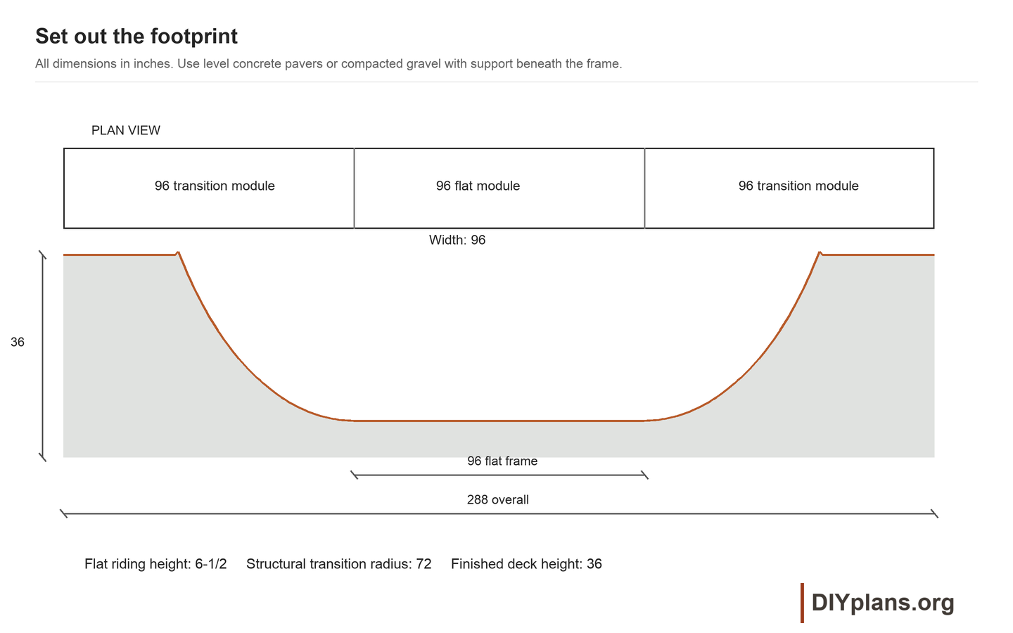
- Clear and mark a 96 x 288-inch rectangle, plus working and riding clearance for the location. Remove vegetation and soft or loose material from the supporting area.
- For concrete pavers, prepare and compact a firm bedding layer. Set the pavers level with one another and place them continuously beneath every bottom edge of the ramp, including the side panels, toe members and flat-bottom framing.
- For a gravel base, use compactable crushed gravel. Compact it in layers and finish it to a firm, level plane beneath every bottom edge; fill and compact low spots before setting the frames.
- Check the base in both directions with a long level. Rebed any rocking pavers and correct settlement or drainage problems. Keep runoff from collecting beneath the wood.
- Arrange safe deck access, perimeter fall protection and any required anchorage for the site before opening the ramp for use.
Check: Every bottom edge has firm, level support with no rocking or unsupported gaps, and water can drain away.
02 Draw the first side profile
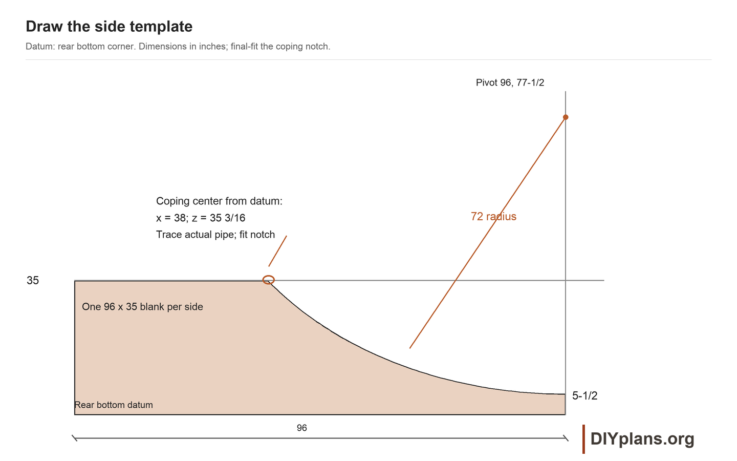
- Mark a 96 x 35-inch blank on one 3/4-inch plywood sheet. Set the rear bottom corner as x=0, z=0; the toe is x=96.
- Extend the layout onto a securely aligned temporary board. Put the trammel pivot at x=96, z=77 1/2 inches and draw a 72-inch-radius arc down to the toe at z=5 1/2 inches.
- Join the arc to the horizontal frame-deck line at z=35 inches. Use the dimensioned drawing for the top junction; do not substitute the original DIYskate profile.
- Mark the coping center at x=38 inches, z=35 3/16 inches from the rear bottom datum. Trace the actual 2 3/8-inch pipe and fit the notch gradually so the pipe seats without forcing the plywood. Check the reveal with the full surface stack before fastening.
Check: The toe, deck line, pivot and coping center agree with the dimensioned drawing.
03 Cut and match four side panels
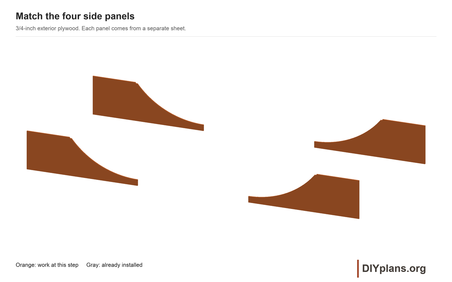
- Cut the first outline and its open coping notch carefully, then fair the curved edge without flattening the transition.
- Trace the checked profile onto three separate sheets. Cut all four panels and clamp them together to compare their edges.
- Label the matched pairs for the left and right modules. Seal fresh cut edges and allow the treatment to dry.
Check: All four profiles match; each coping fits its notch without forcing the plywood.
04 Cut and label the framing
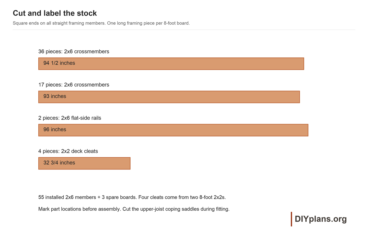
- Cut thirty-six 2x6 members to 94-1/2 inches and seventeen to 93 inches. Retain two full 96-inch boards for the flat-side rails.
- Cut four 2x2 cleats to 32-3/4 inches. Label every piece from the cut list, including the eight paired seam-backers.
- Set aside twisted, split or badly knotted members. Apply compatible cut-end treatment where required.
Check: There are 55 labeled 2x6 members and four 32-3/4-inch cleats, with each backing length assigned correctly.
05 Assemble the deck frames
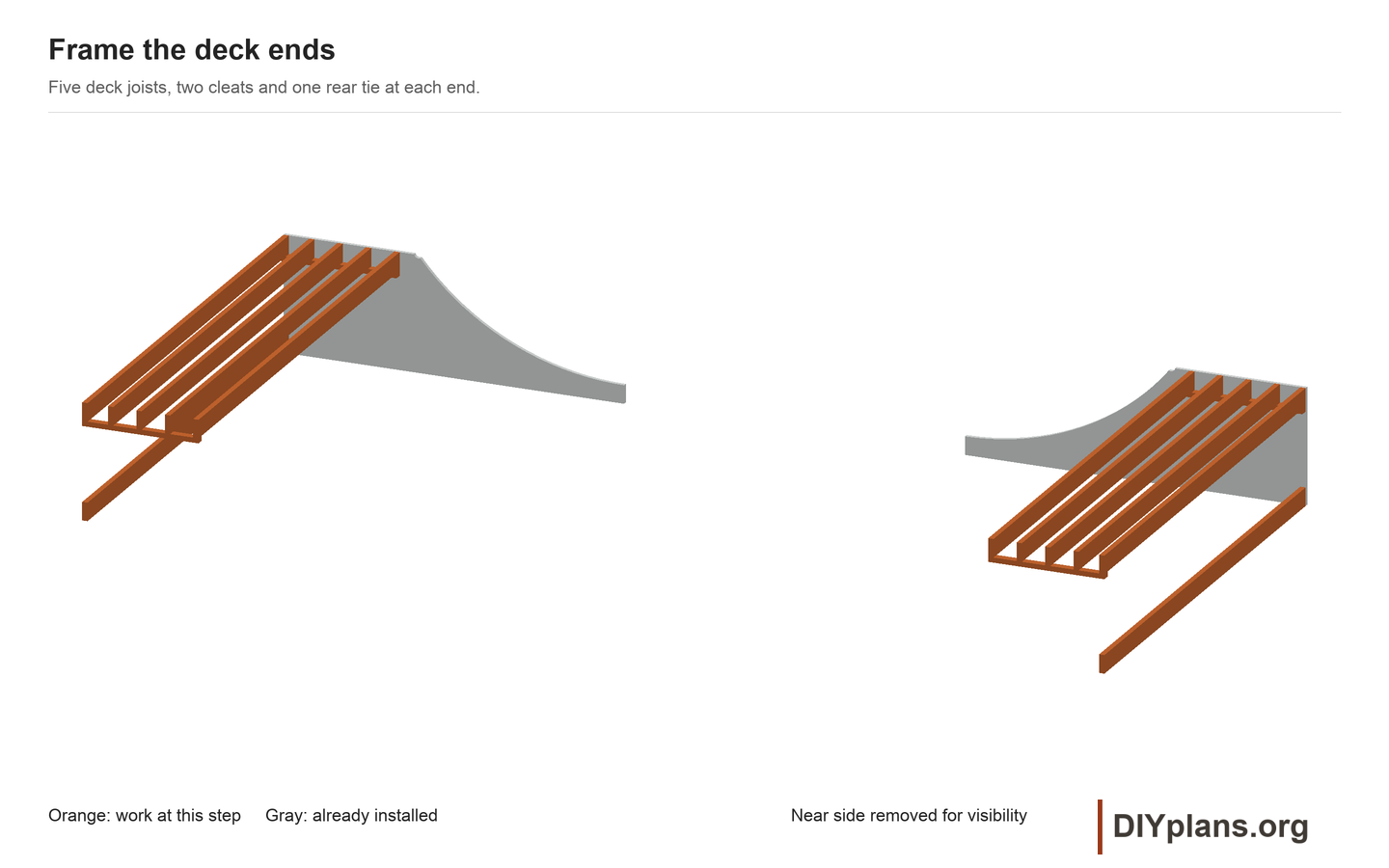
- Brace a pair of side panels with their outside faces 96 inches apart. Check the inside width before cutting any crossmember.
- Set five 94-1/2-inch deck joists with top faces at 35 inches. Mark their centerlines 3/4, 8, 16, 24 and 32 inches from the rear edge.
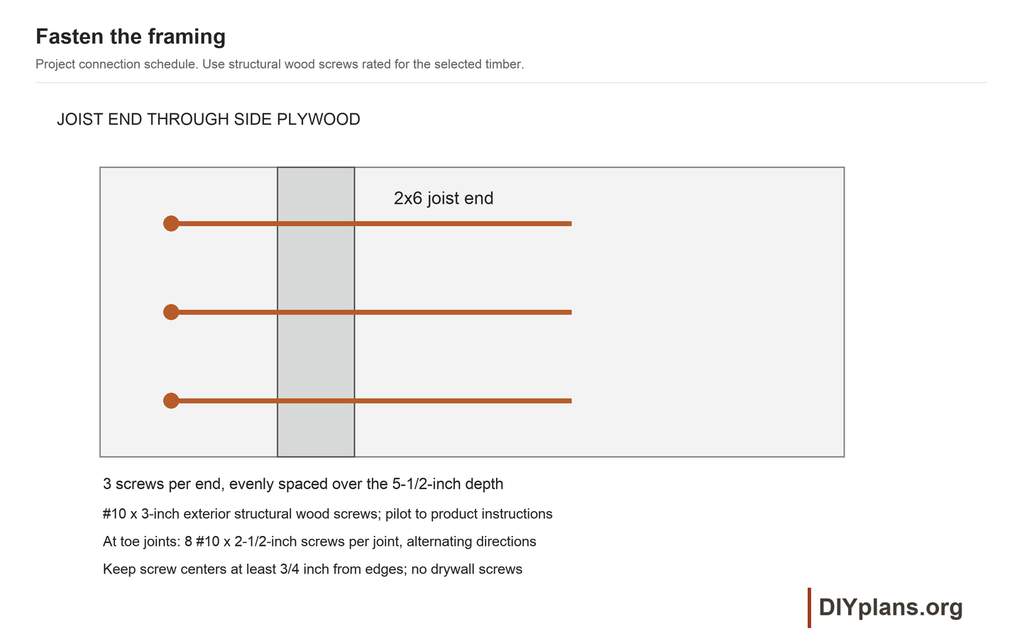
- Pilot and drive three #10 x 3-inch exterior structural wood screws through each side panel into each joist end. Space them evenly over the joist depth, with centers at least 3/4 inch from edges. Follow the screw maker's pilot requirements.
- Place a 32-3/4-inch 2x2 cleat under the joist ends on each inside face. Its top is 29-1/2 inches above the supporting base. Drive five #8 x 1-5/8-inch exterior screws through the plywood into each cleat; the joists bear on the cleats.
- Fit the rear bottom tie, with its bottom on the supporting base. Fasten three structural screws at each end. Repeat for the other transition module.
Check: Both decks are square, braced and level, with supported and positively fastened joist ends.
06 Set the transition joists
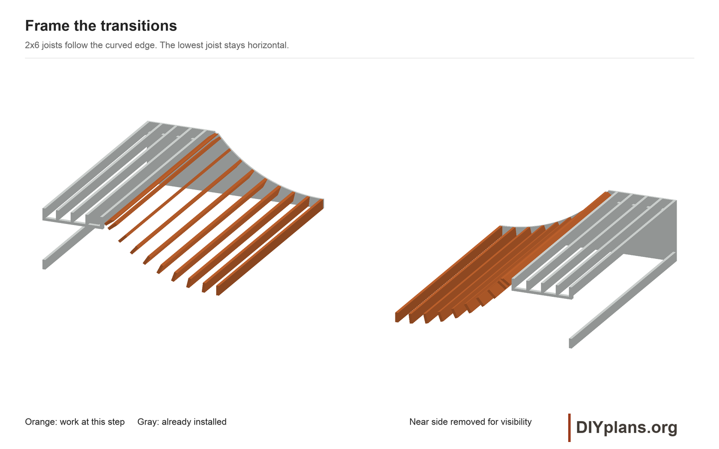
- Install the lowest 94-1/2-inch joist horizontally, with its bottom on the supporting base and its front edge flush with the toe.
- Mark arc stations 8, 16, 24, 32, 40, 48, 56, 64 and 66 3/4 inches up from the toe along the curved edge. These locate the centers of the remaining joist top faces.
- Set each joist tangent to the curved edge. The cut-list angle is its rotation from horizontal, not a bevel cut on the board ends. Clamp the ends and drive three #10 x 3-inch structural wood screws through each side panel.
- Fit the uppermost joist's coping notch from the matched side notches, then remove that joist to cut and fair the saddle. The CAD shows its finished shape. Keep the full remaining depth and do not deepen the notch to adjust the reveal.
- Check the support line with a flexible straightedge and a scrap of plywood. Correct a high corner before sheathing.
Check: The lowest joists sit on the supporting base; the remaining joists follow the curve with no more than 8 inches between arc stations.
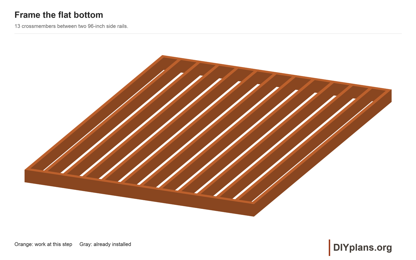
07 Assemble the flat bottom
- Place the two 96-inch side rails 96 inches apart outside-to-outside.
- Fit the thirteen 93-inch crossmembers with centerlines at 3/4, 8, 16, 24, 32, 40, 48, 56, 64, 72, 80, 88 and 95 1/4 inches from the flat's left end.
- Square the frame by comparing diagonals. Pilot and drive three #10 x 3-inch structural wood screws through each side rail into each crossmember end.
Check: The flat measures 96 x 96 inches and its frame top is 5 1/2 inches above the supporting base.
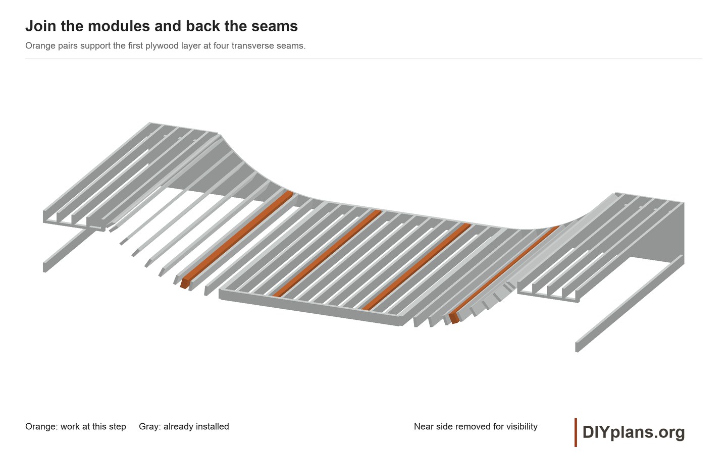
08 Join the modules and support the seams
- Place the flat between the transitions on the prepared base. Clamp both toe joints and check the 288-inch overall length and aligned 5-1/2-inch frame tops.
- Join the adjacent end joists with eight #10 x 2-1/2-inch structural wood screws at each toe joint. Space them across the width, alternate driving directions, and keep the holes clear of the end-connection screws.
- Measure first-layer seam stations 48, 96, 144 and 192 inches along the bare framing, starting at the top of the left curved profile. Use a flexible tape, not a horizontal measurement.
- Fit a pair of 2x6 backers at each station, centered together under the seam. Use 94-1/2-inch pieces at the two transition seams and 93-inch pieces at the two flat seams.
- Seat backers tangent to the local surface and secure each end with three #10 x 3-inch structural screws. Each piece must reach and fasten to its side support. The paired top faces support both plywood edges.
Check: The connected frame cannot shift at either toe joint; every first-layer seam has fully attached backing.
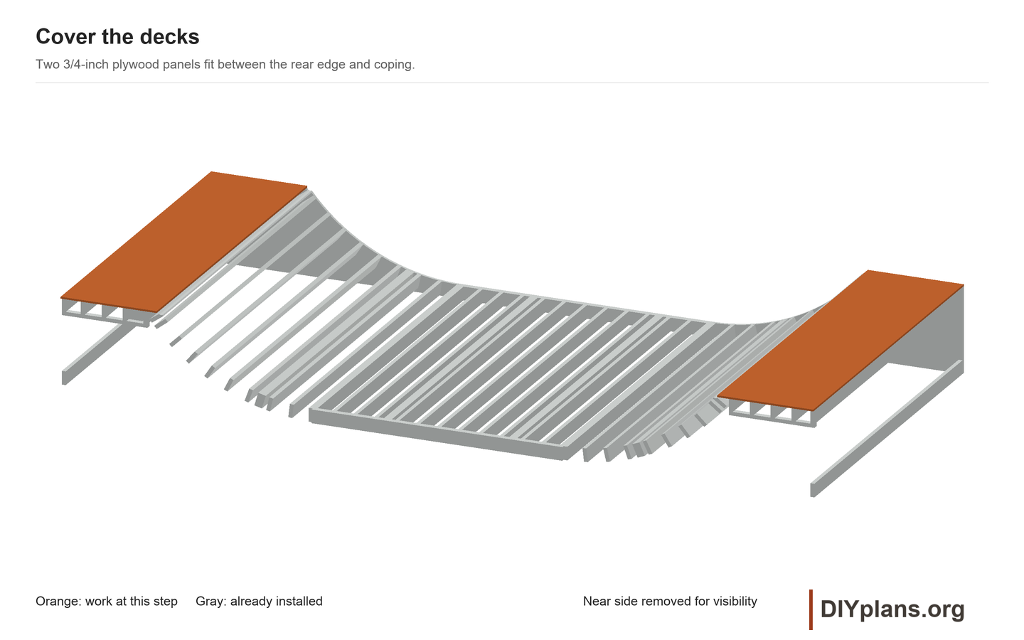
09 Fit the deck plywood
- Rough cut two 3/4-inch deck panels 36 3/4 x 96 inches. Use the loose coping as a gauge and trim the front edge to leave 1/16 inch of clearance.
- Mark the five deck-joist lines and both side edges. Fasten with #8 x 1-5/8-inch exterior screws at 8-inch centers on the perimeter and no more than 12-inch centers along each joist.
- Seat screw heads flush. Recoat exposed edges and let the wood dry. Remove the loose coping while finishing the surfacing.
Check: Both deck panels sit flat, have secured perimeter edges, and leave room for the surface caps.
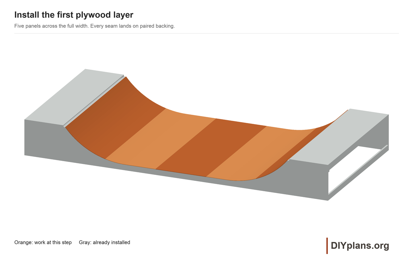
10 Install the first riding layer
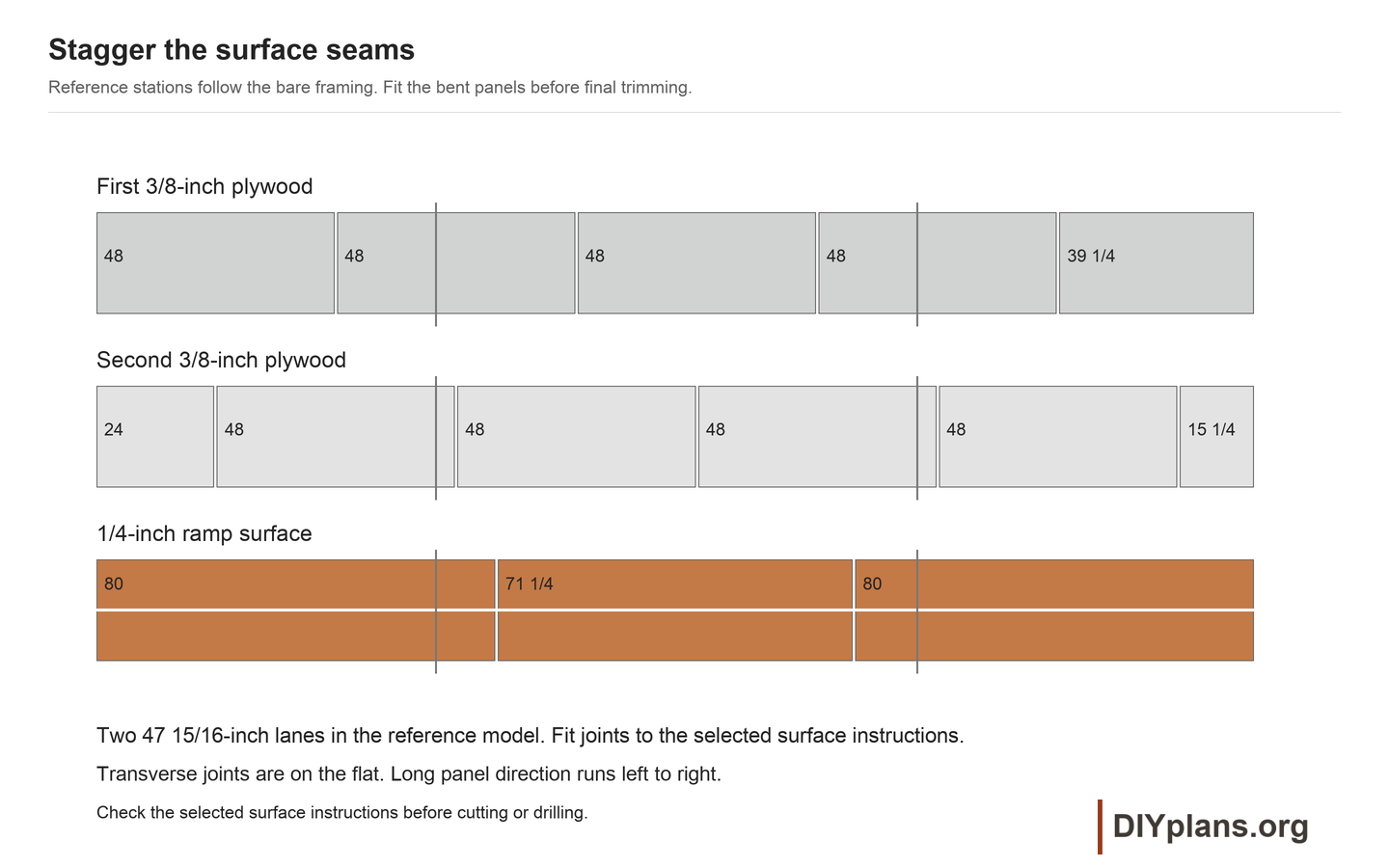
- Mark structural-path stations 0, 48, 96, 144, 192 and 231 1/4 inches from the same upper left profile reference used for the seam backing. Transfer those marks to the panel edges before covering them.
- Fit 3/8-inch plywood across the full 96-inch width at those intervals. These are reference-path lengths; trial bend and trim each panel to its actual position.
- Start at one upper transition with a helper holding the panel tight. Work steadily down its support lines so the sheet seats without a kink.
- Use the project's 1/16-inch plywood seam allowance unless the selected plywood requires another gap. Center the seams over their paired backing and fasten both edges.
- Use #8 x 1-5/8-inch exterior screws at no more than 12-inch centers across each supporting joist and paired seam-backer. Mark the support lines before covering them.
- Use the loose coping to mark and trim the upper panel ends. Remove the pipe after fitting; final fastening comes after the top surface.
Check: The first layer has continuous support, secure seams and no raised corners.
11 Stagger the second riding layer
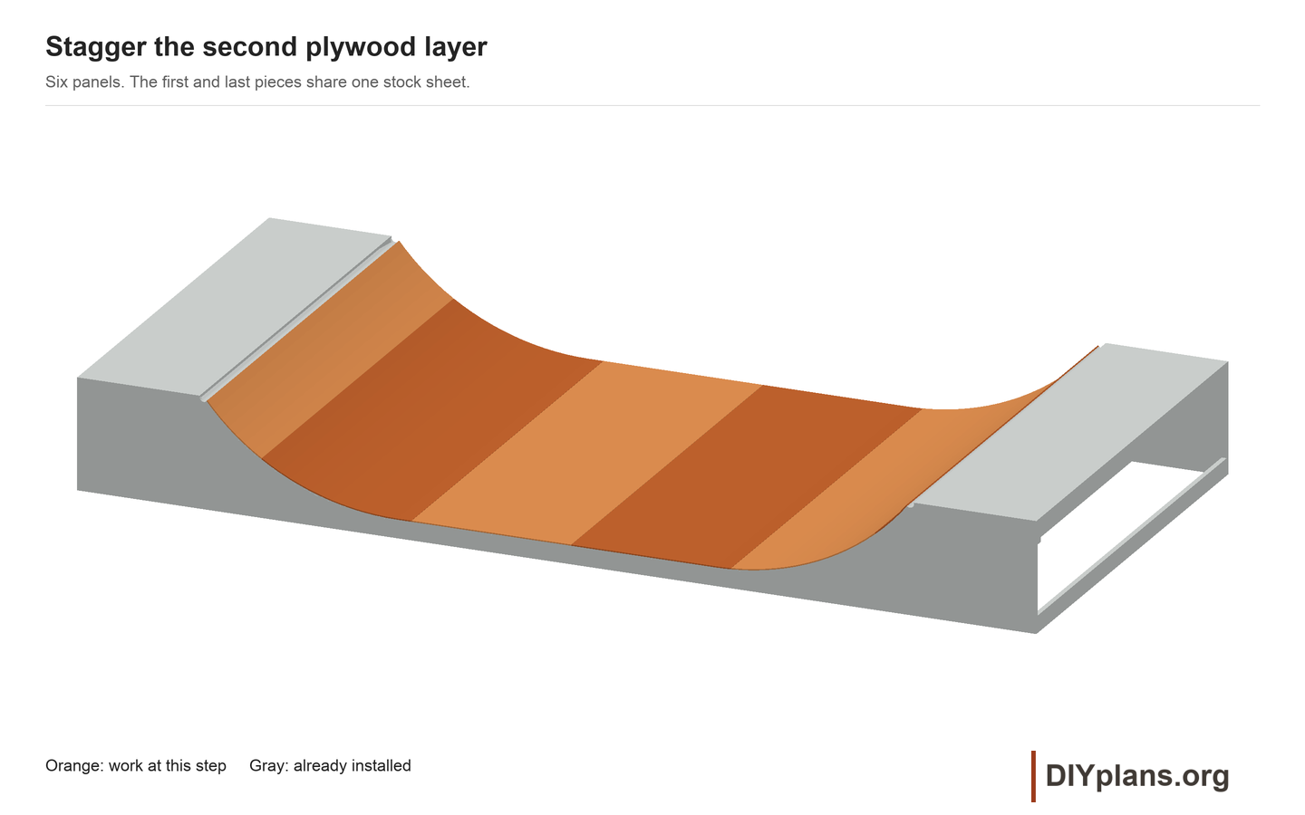
- Mark second-layer reference stations 0, 24, 72, 120, 168, 216 and 231 1/4 inches.
- Cut the first panel from half a sheet and retain its offcut for the final short panel. Fit the intervening full panels and trim the ends on the ramp.
- Maintain the plywood seam gaps. Use #8 x 1-5/8-inch exterior screws along the marked joist lines at no more than 12-inch centers, with heads flush. Keep the second-layer seams offset from the first.
- Run a straightedge and your hand over the complete substrate. Correct proud screws, steps and voids; allow any protective coating to dry fully.
Check: The two 3/8-inch layers form a smooth, dry, 3/4-inch substrate.
12 Lay out the top-surface blanks
- For Gator Skins, keep panels dry in their packaging until needed. Install above freezing; temperatures above 50 F and at least an hour flat in the sun are recommended. For Skatelite Pro, keep sheets flat, dry and supported, and follow the delivered storage and installation directions.
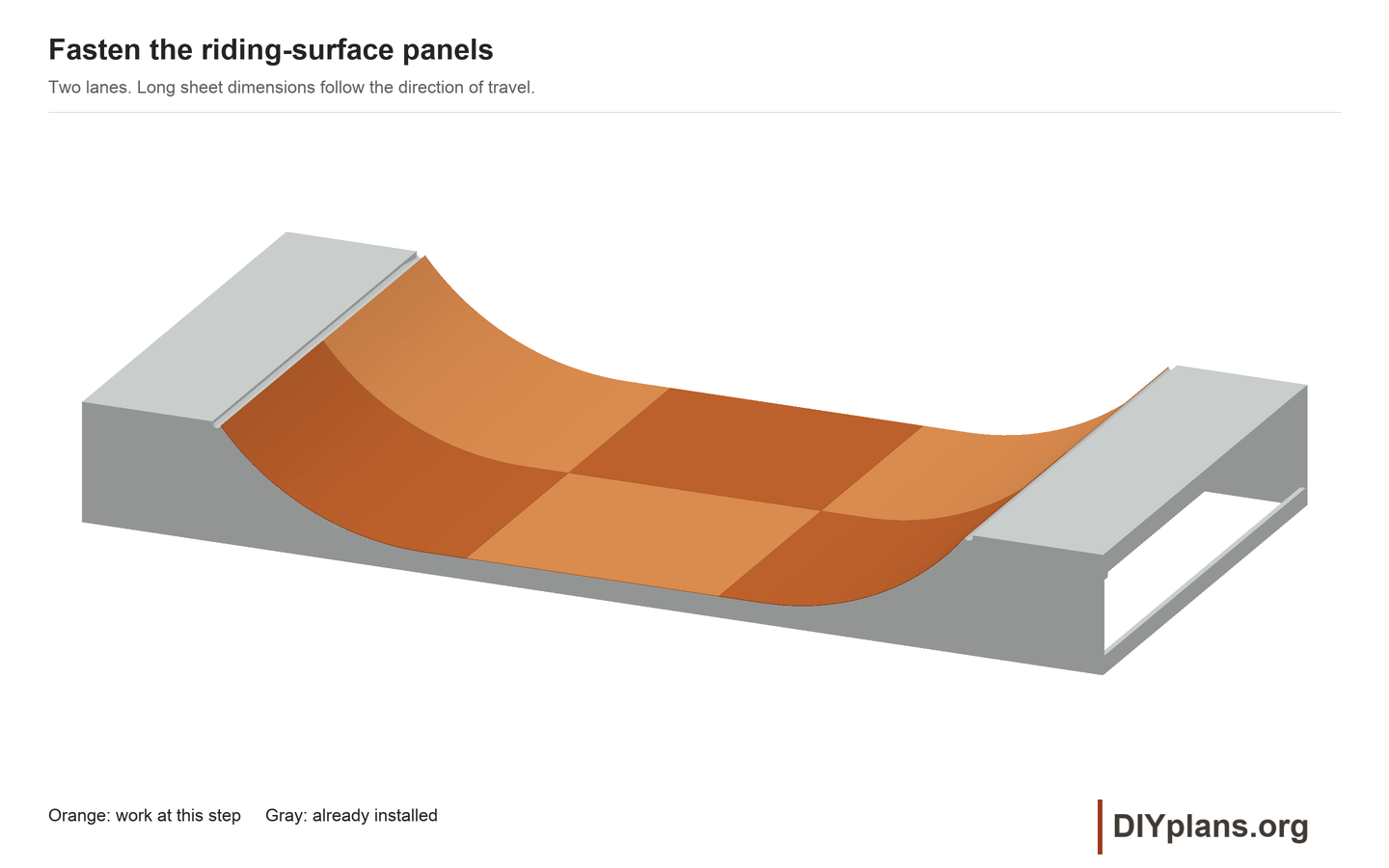
- Orient the long dimension of each riding sheet along the direction of travel over the transition.
- Use the following rough-cut layout for either 1/4-inch surface. Its lane widths allow the project 1/8-inch joints. Check delivered-product joint requirements, then final-fit the panel edges on the ramp before drilling.
- Prepare two lanes 47 15/16 inches wide. For each lane, rough cut two 80-inch end blanks and one 71 1/4-inch middle blank; measure and trim final lengths on the ramp.
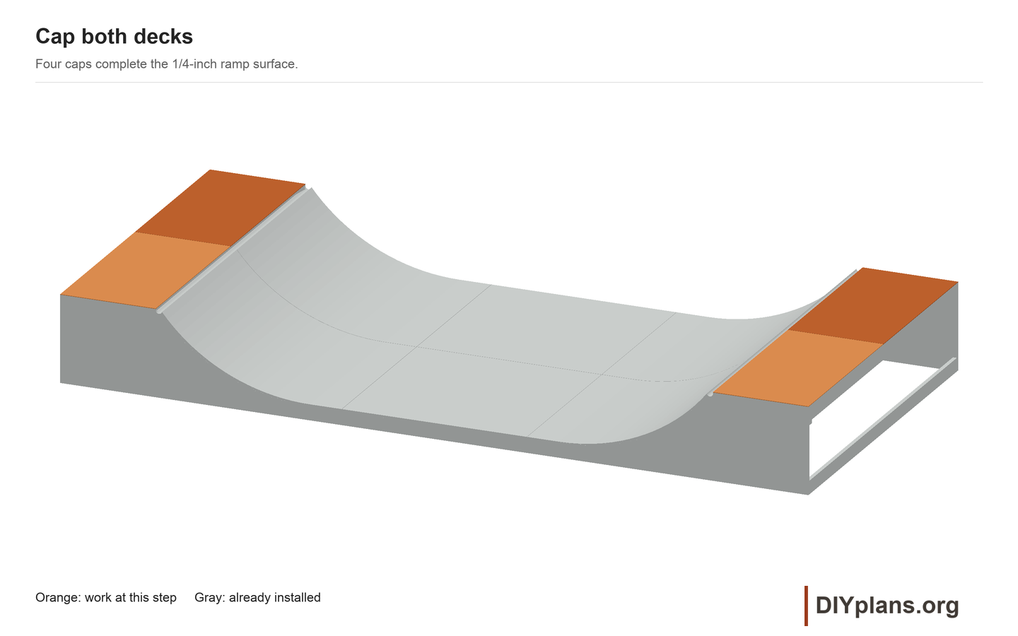
- Rough cut four deck caps 36-3/4 x 47-15/16 inches from the remaining two sheets. Fit their final front edges with the loose coping. Retain offcuts for fastener trials.
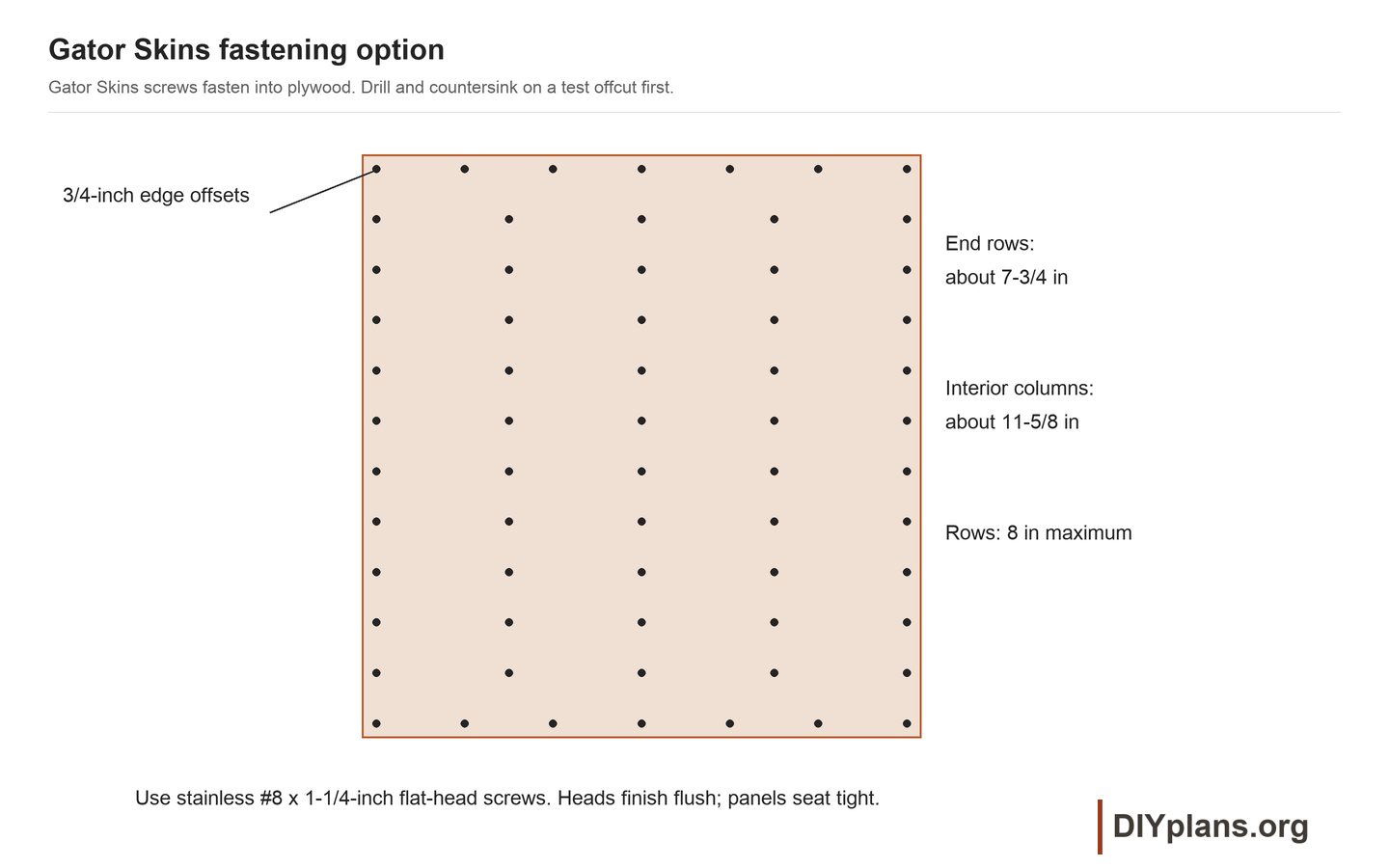
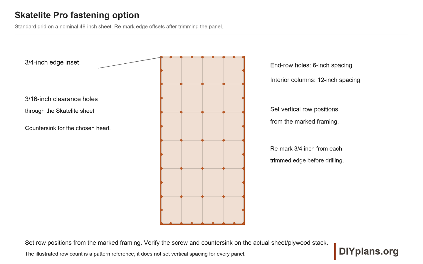
- Choose the fastening detail for your top surface. Test a stainless #8 x 1 1/4-inch screw and countersink on an offcut of that sheet over the full 3/4-inch plywood stack. For Skatelite, drill a 3/16-inch clearance hole through the top sheet first. Pilot the wood as the screw maker directs. The head must finish flush and hold firmly without cracking, stripping or lifting the sheet.
Check: Sheet direction, actual stock size, seam allowances and fastener settings are confirmed before final cuts.
13 Fasten the riding surface
- Dry fit both end panels in one lane and mark their joints on the flat, near reference stations 80 and 151 1/4 inches. Fit the middle panel between them.
- Trim along the actual bent surface and retain the selected joint allowance at both transverse joints and between lanes. Reference path lengths in the cut list are rough layout dimensions; fit final lengths on the ramp.
- For Gator Skins, place screw centers 3/4 inch from panel edges. Space screws no more than 7 3/4 inches apart in the two end rows, about 11 5/8 inches across interior rows, and no more than 8 inches between rows. Redistribute the pattern evenly on trimmed panels.
- For Skatelite Pro, use the separate standard-grid detail. Keep screw centers 3/4 inch from trimmed edges, with interior columns no more than 12 inches apart and end-row screws no more than 6 inches apart. Locate field rows from the marked framing lines and mark the panel-end rows separately. Drill 3/16-inch clearance holes through the Skatelite and countersink for the actual screw head before piloting the plywood. Add a screw midway between adjacent field rows along both long panel edges, as shown in the Skatelite detail.
- Pilot and countersink before fastening. Seat the sheet against the plywood as you work from the top down; stop if a gap, crack or buckled edge develops.
- Repeat for the second lane. Finish all heads flush with the riding face.
Check: Both lanes lie tight to the plywood, seams are even, and no screw head or panel edge catches a straightedge.
14 Install the deck caps
- Rough cut and fit two 36-3/4 x 47-15/16-inch surface caps on each deck. Use the loose pipe to mark the finished front edge, leave 1/16-inch pipe clearance, and retain the 1/8-inch joint between caps.
- Mark, drill and countersink cap fasteners using the selected surface detail and the proven coupon settings. Use the same edge insets and maximum spacing on each trimmed cap, with rows positioned from the marked deck joists. Fasten to the solid deck plywood and seat each head flush.
- Check every deck end and corner for firm attachment. Keep the exposed ramp surface free of paint or sealant unless its manufacturer specifies otherwise.
Check: All four caps sit tightly on the plywood, keep their pipe clearances, and finish 36 inches above the supporting base.
15 Fit and restrain the coping
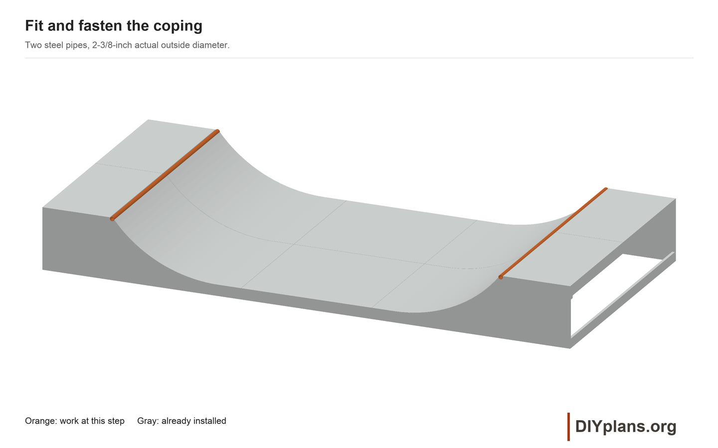
- Cut both NPS 2 Schedule 80 pipes to 96 inches. Confirm a 2-3/8-inch outside diameter and deburr the ends.
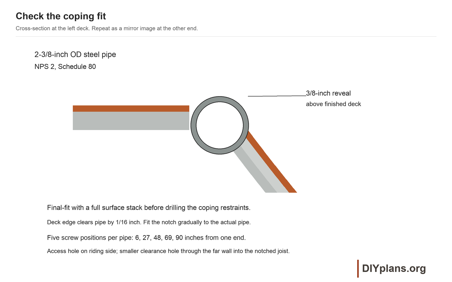
- Seat each pipe in the side and upper-joist saddles. Check 3/8-inch projection above the finished deck and normal to the riding curve using a straightedge and the finished surface.
- Mark five fastening positions, 6, 27, 48, 69 and 90 inches from one end. Aim each screw through the pipe into the middle of the notched upper joist, away from its edges.
- Remove the pipe. Drill a 1/2-inch access hole through the riding-side wall and a 1/4-inch clearance hole through the opposite wall at each position. Deburr both walls; keep each paired set aligned with the marked joist target.
- Refit the pipe, pilot the timber to the screw maker's instructions, and drive a #12 x 3-inch stainless flat-head wood screw through each access hole into the far wall and solid joist. The head bears on the far wall inside the pipe.
- Tighten all five screws without stripping the wood. Check that the pipe cannot turn or lift, and file any remaining sharp access-hole edge.
Check: Neither pipe rotates or lifts, and the complete surface coupon clears the coping consistently.
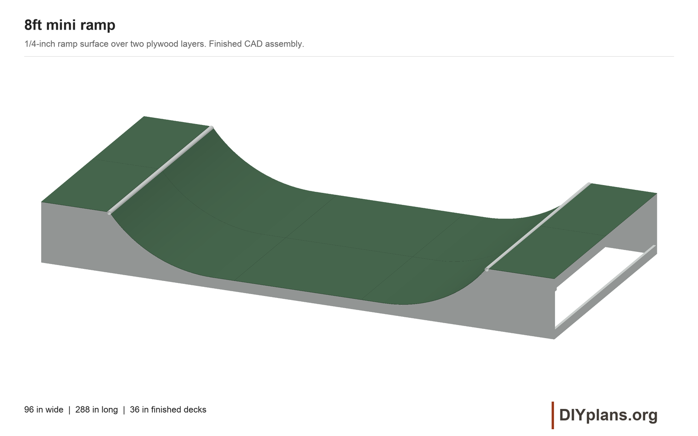
16 Inspect the completed assembly
- Check the 96-inch width, 288-inch length, 36-inch deck height and 6 1/2-inch flat height against the drawings.
- Inspect every frame connection, module joint and coping restraint. Remove all temporary braces only after the permanent connections are complete.
- Sweep and wipe the surface, then check all seams, edges and screw heads by hand. Correct loose hardware, splinters, sharp metal, cracks and standing-water traps.
- Complete the site-specific access, guards and anchorage before use. Have a competent ramp builder inspect the finished installation; the digital package does not establish a tested load capacity.
- Inspect again before each session and after rain or a prolonged idle period. Keep wet or damaged surfaces closed, and replace deteriorated substrate before covering it again.
Check: The assembly and site are ready for an independent physical inspection; no structural or ride-test result is implied.